2007 YAMAHA GRIZZLY 700 bulb
[x] Cancel search: bulbPage 10 of 166
Checking and lubricating the front and
rear brake levers .................................... 8-52
Checking and lubricating the brake
pedal ...................................................... 8-53
Checking the wheel bearings ................... 8-53
Lubricating the drive shaft universal
joint ......................................................... 8-53
Checking the stabilizer bushes ................ 8-53
Lubricating the upper and lower arm
pivots ...................................................... 8-54
Lubricating the knuckle pivots .................. 8-54
Lubricating the knuckle shafts .................. 8-54
Lubricating the steering shaft ................... 8-54
Battery ...................................................... 8-55
Replacing a fuse ...................................... 8-56
Replacing a headlight bulb ....................... 8-58
Adjusting a headlight beam ...................... 8-61
Replacing the tail/brake light bulb ............ 8-61
Removing a wheel .................................... 8-62
Installing a wheel ...................................... 8-63
Troubleshooting ....................................... 8-64
Troubleshooting charts ............................. 8-65
CLEANING AND STORAGE .......................... 9-1
Cleaning ..................................................... 9-1
Storage ....................................................... 9-2SPECIFICATIONS .......................................10-1
CONSUMER INFORMATION.......................11-1
Identification numbers ...............................11-1
U3B460E0.book Page 3 Friday, May 12, 2006 2:51 PM
Page 143 of 166
8-58
8
WARNING
EWB02171Always use a fuse of the specified rating, and
never use a substitute object in place of the
proper fuse. An improper fuse or a substitute
object can cause damage to the electrical sys-tem, which could lead to a fire.
3. Turn the key to “ON” and turn on the electrical
circuits to check if the devices operate.
4. If the fuse immediately blows again, have a
Yamaha dealer check the electrical system.EBU27440Replacing a headlight bulb If a headlight bulb burns out, replace it as follows.
1. Remove the cover at the rear of the headlight
by pulling it off. Specified fuses:
Main fuse:
40.0 A
Headlight fuse:
15.0 A
Ignition fuse:
10.0 A
Four-wheel-drive motor fuse:
10.0 A
Signaling system fuse:
5.0 A
Auxiliary DC jack fuse:
15.0 A
Radiator fan fuse:
15.0 A
Fuel injection system fuse:
15.0 A
EPS fuse:
40.0 A
U3B460E0.book Page 58 Friday, May 12, 2006 2:51 PM
Page 144 of 166
8-59
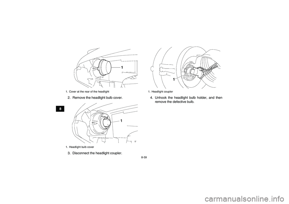
82. Remove the headlight bulb cover.
3. Disconnect the headlight coupler.4. Unhook the headlight bulb holder, and then
remove the defective bulb.
1. Cover at the rear of the headlight
1. Headlight bulb cover
1. Headlight coupler
U3B460E0.book Page 59 Friday, May 12, 2006 2:51 PM
Page 145 of 166

8-60
8
WARNING
EWB02220A headlight bulb is hot when it is on and imme-
diately after it is turned off. Wait for the bulb to
cool before touching or removing it. You can
be burned or a fire could start if the bulb touch-es something flammable.
5. Place a new headlight bulb into position, and
then secure it with the bulb holder.
CAUTION:ECB00650Do not touch the glass part of the headlight
bulb to keep it free from oil, otherwise the
transparency of the glass, the luminosity of the
bulb, and the bulb life will be adversely affect-
ed. Thoroughly clean off any dirt and finger-
prints on the headlight bulb using a clothmoistened with alcohol or thinner.
6. Connect the headlight coupler.
7. Install the headlight bulb cover.
8. Install the cover at the rear of the headlight.
1. Headlight bulb holder
2. Headlight bulb
1. Do not touch the glass part of the bulb.
U3B460E0.book Page 60 Friday, May 12, 2006 2:51 PM
Page 146 of 166
8-61
8
CAUTION:ECB00670Make sure the headlight bulb holder cover is
securely fitted over the bulb holder and seatedproperly.
9. Adjust the headlight beam if necessary.EBU25550Adjusting a headlight beam CAUTION:ECB00690It is advisable to have a Yamaha dealer makethis adjustment.
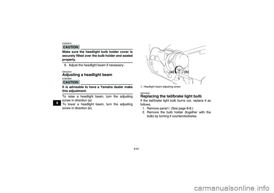
To raise a headlight beam, turn the adjusting
screw in direction (a).
To lower a headlight beam, turn the adjusting
screw in direction (b).
EBU25640Replacing the tail/brake light bulb If the tail/brake light bulb burns out, replace it as
follows.
1. Remove panel I. (See page 8-8.)
2. Remove the bulb holder (together with the
bulb) by turning it counterclockwise.1. Headlight beam adjusting screw
U3B460E0.book Page 61 Friday, May 12, 2006 2:51 PM
Page 147 of 166
8-62
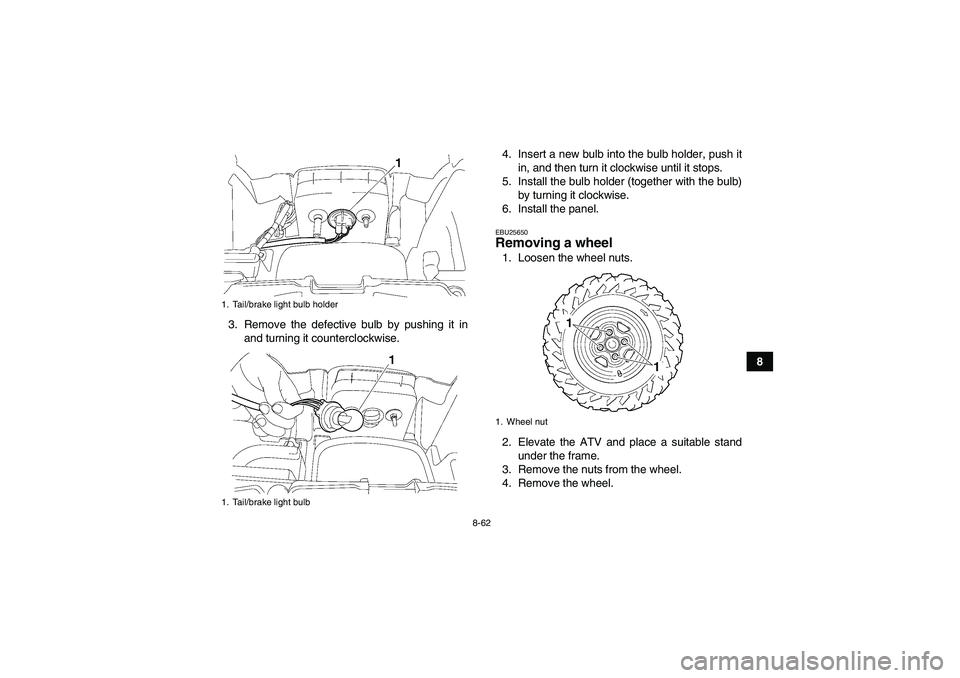
8 3. Remove the defective bulb by pushing it in
and turning it counterclockwise.4. Insert a new bulb into the bulb holder, push it
in, and then turn it clockwise until it stops.
5. Install the bulb holder (together with the bulb)
by turning it clockwise.
6. Install the panel.
EBU25650Removing a wheel 1. Loosen the wheel nuts.
2. Elevate the ATV and place a suitable stand
under the frame.
3. Remove the nuts from the wheel.
4. Remove the wheel.
1. Tail/brake light bulb holder
1. Tail/brake light bulb
1. Wheel nut
U3B460E0.book Page 62 Friday, May 12, 2006 2:51 PM
Page 158 of 166

10-4
10
Rear:
33.0 kPa (4.8 psi) (0.330 kgf/cm²)
Front wheel:Wheel type:
Panel wheel
Rim size:
12 x 6.0ATRear wheel:Wheel type:
Panel wheel
Rim size:
12 x 7.5ATFront brake:Type:
Dual disc brake
Operation:
Right hand operation
Recommended fluid:
DOT 4Rear brake:Type:
Dual disc brake
Operation:
Left hand and right foot operation
Recommended fluid:
DOT 4Front suspension:Type:
Double wishbone
Spring/shock absorber type:
Coil spring/oil damperWheel travel:
180 mm (7.1 in)
Rear suspension:Type:
Double wishbone
Spring/shock absorber type:
Coil spring/oil damper
Wheel travel:
230 mm (9.1 in)Electrical system:Ignition system:
Transistorized coil ignition (digital)
Charging system:
AC magnetoBattery:Model:
YTX20L-BS
Voltage, capacity:
12 V, 18.0 AhHeadlight:Bulb type:
Halogen bulbBulb voltage, wattage x quantity:Headlight:
12 V, 35.0/35.0 W × 2
Tail/brake light:
12 V, 5.0/21.0 W
Meter lighting:
EL
Neutral indicator light:
LED
U3B460E0.book Page 4 Friday, May 12, 2006 2:51 PM
Page 163 of 166

INDEX
AAccessories and loading ................................................ 6-6
Accessories, auxiliary jack ........................................... 4-22
Air filter element, cleaning ............................................ 8-36
Axle boots .................................................................... 8-51BBattery .......................................................................... 8-55
Brake fluid, changing ................................................... 8-47
Brake fluid level, checking ........................................... 8-46
Brake hose protectors, checking the rear .................... 8-45
Brake lever, front .......................................................... 4-14
Brake levers, checking and lubricating ........................ 8-52
Brake pads, checking the front and rear ...................... 8-44
Brake pedal and rear brake lever ................................. 4-14
Brake pedal, checking and lubricating ......................... 8-53
Brake pedal free play and brake pedal position,
adjusting and checking .............................................. 8-49
Brakes, front and rear .................................................... 5-4CCables, checking and lubricating ................................. 8-51
Carrier, front ................................................................. 4-21
Carrier, rear .................................................................. 4-21
Chassis fasteners .......................................................... 5-7
Cleaning ......................................................................... 9-1
Coolant .................................................................. 5-3, 8-30
Coolant temperature warning light ................................. 4-2DDifferential gear lock indicator light ................................ 4-4Differential gear oil ................................................ 5-3, 8-28
Drive select lever ......................................................... 4-15
Drive select lever and driving in reverse ........................ 6-2
Drive select lever safety system cable, adjusting ........ 8-44
Drive shaft universal joint, lubricating .......................... 8-53
EEngine break-in .............................................................. 6-4
Engine idling speed ..................................................... 8-42
Engine oil ....................................................................... 5-3
Engine oil and oil filter cartridge ................................... 8-22
Engine stop switch ......................................................... 4-7
Engine trouble warning light .......................................... 4-3
EPS warning light .......................................................... 4-3FFinal gear oil ......................................................... 5-3, 8-26
Four-wheel-drive/differential gear lock indicator ............ 4-3
Front and rear brake lever free play, checking ............ 8-48
Fuel ....................................................................... 4-16, 5-3
Fuel tank cap ............................................................... 4-15
Fuses, replacing .......................................................... 8-56HHandlebar switches ....................................................... 4-7
Headlight beam, adjusting ........................................... 8-61
Headlight bulb, replacing ............................................. 8-58
High-range indicator light ............................................... 4-4
Horn switch .................................................................... 4-8IIdentification numbers .................................................. 11-1
U3B460E0.book Page 1 Friday, May 12, 2006 2:51 PM