Page 123 of 166
8-38
8 3. Remove the sponge material and the mesh
from the air filter case.4. Clean the mesh with solvent, and then wipe
the solvent off.
5. Wash the sponge material gently, but thor-
oughly, in solvent.
WARNING
EWB01940Always use parts cleaning solvent to clean the
sponge material. Never use low-flash-point
solvents or gasoline to clean the sponge mate-
rial because the engine could catch fire or ex-plode.
6. Squeeze the excess solvent out of the sponge
material and let it dry.
1. Air filter case holder
2. Air filter case cover
1. Sponge material
2. Air filter mesh
U3B460E0.book Page 38 Friday, May 12, 2006 2:51 PM
Page 124 of 166

8-39
8
CAUTION:ECB00440Do not twist the sponge material when squeez-ing it.
7. Check the sponge material and replace it if
damaged.
8. Apply Yamaha foam air filter oil or other qual-
ity foam air filter oil to the sponge material.NOTE:The sponge material should be wet but not drip-ping.
9. Install the mesh and the sponge material into
the air filter case.
10. Insert the projections on the air filter case cov-
er into the holders on the air filter case, and
then install the air filter case cover by hooking
the holders onto the cover.11. Install the panel.
NOTE:The air filter element should be cleaned every 20–
40 hours. It should be cleaned and lubricated more
often if the ATV is operated in extremely dusty ar-
eas. Each time the air filter element maintenance
is performed, check the air inlet of the air filter case
for obstructions. Check the air filter case rubber
joint to the throttle body and the rubber joint mani-
fold fittings for an air-tight seal. Tighten all fittings
securely to avoid the possibility of unfiltered air en-tering the engine.
U3B460E0.book Page 39 Friday, May 12, 2006 2:51 PM
Page 125 of 166
8-40
8
CAUTION:ECB00760�Make sure that the air filter element is prop-
erly seated in the air filter case.�Never operate the engine with the air filter el-
ement removed. This will allow unfiltered air
to enter the engine, causing rapid engine
wear and possible engine damage. Addition-
ally, operation without the air filter element
will affect the fuel injection system with sub-
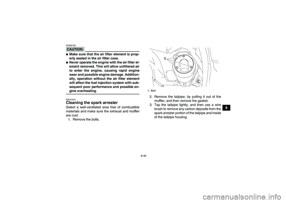
sequent poor performance and possible en-gine overheating.EBU27810Cleaning the spark arrester Select a well-ventilated area free of combustible
materials and make sure the exhaust and muffler
are cool.
1. Remove the bolts.2. Remove the tailpipe, by pulling it out of the
muffler, and then remove the gasket.
3. Tap the tailpipe lightly, and then use a wire
brush to remove any carbon deposits from the
spark arrester portion of the tailpipe and inside
of the tailpipe housing.
1. Bolt
U3B460E0.book Page 40 Friday, May 12, 2006 2:51 PM
Page 126 of 166
8-41
84. Install the gasket, and then insert the tailpipe
into the muffler and align the bolt holes.
5. Install the bolts and tighten them to the speci-
fied torque.
6. Remove the purging bolt.7. Start the engine and rev it up approximately
twenty times while momentarily creating ex-
haust system back pressure by blocking the
end of the muffler with a shop towel.
8. Stop the engine and allow the exhaust pipe to
cool.
9. Install the purging bolt and tighten it to the
specified torque.
1. Tailpipe
2. Spark arrester
3. GasketTightening torque:
Tailpipe bolt:
10 Nm (1.0 m·kgf, 7.2 ft·lbf)
1. Purging boltTightening torque:
Purging bolt:
27 Nm (2.7 m·kgf, 19 ft·lbf)
U3B460E0.book Page 41 Friday, May 12, 2006 2:51 PM
Page 127 of 166

8-42
8
WARNING
EWB02380Never run the engine in an enclosed area when
purging the spark arrester, otherwise it could
cause injury to the eyes, burns, carbon monox-
ide poisoning, possibly leading to death, and
start a fire.�Always let the exhaust system cool prior to
touching exhaust components.�Always wear eye protection, and make sure
no one is behind the ATV.�Make sure there are no combustible materi-als in the area.EBU23930V-belt case drain plug After riding in water deep enough to allow it to en-
ter the V-belt case, remove this plug to drain the
water from the case.NOTE:If water drains from the V-belt case after removing
the plug, have a Yamaha dealer check the ATV asthe water may affect other engine parts.
EBU27310Adjusting the engine idling speed The engine idling speed must be checked and, if
necessary, adjusted as follows at the intervals
specified in the periodic maintenance and lubrica-
tion chart.NOTE:A diagnostic tachometer is needed to make thisadjustment.
1. Start the engine and warm it up.1. V-belt case drain plug
U3B460E0.book Page 42 Friday, May 12, 2006 2:51 PM
Page 128 of 166

3. Attach the tachometer to the spark plug lead.
4. Check the engine idling speed and, if nec")
8-43
8
NOTE:The engine is warm when it quickly responds to thethrottle.
2. Remove panel C. (See page 8-8.)
3. Attach the tachometer to the spark plug lead.
4. Check the engine idling speed and, if neces-
sary, adjust it to specification by turning the
idle adjusting screw. To increase the engine
idling speed, turn the idle adjusting screw in
direction (a), and to decrease it, turn the screw
in direction (b).
NOTE:If the specified idling speed cannot be obtained as
described above, have a Yamaha dealer make theadjustment.
5. Install the panel.EBU24043Adjusting the throttle cable free play The throttle cable free play should be checked
and, if necessary, adjusted at the intervals speci-
fied in the periodic maintenance and lubrication
chart.
The throttle cable free play should measure 3.0–
5.0 mm (0.12–0.20 in) at the throttle lever. Period-
ically check the throttle cable free play and, if nec-
essary, adjust it as follows.NOTE:The engine idling speed must be checked, and ad-
justed if necessary, before adjusting the throttle ca-ble free play.
1. Loosen the locknut.
1. Idle adjusting screw
Engine idling speed:
1350–1450 r/min
U3B460E0.book Page 43 Tuesday, May 16, 2006 4:35 PM
Page 129 of 166
. To decrease
the throttle cable free play, turn the adjusting
bolt in direction (b).
3. Tighten the locknut")
8-44
8 2. To increase the throttle cable free play, turn
the adjusting bolt in direction (a). To decrease
the throttle cable free play, turn the adjusting
bolt in direction (b).
3. Tighten the locknut.
EBU24060Valve clearance The valve clearance changes with use, resulting in
improper air-fuel mixture and/or engine noise. To
prevent this from occurring, the valve clearancemust be adjusted by a Yamaha dealer at the inter-
vals specified in the periodic maintenance and lu-
brication chart.
EBU24070Adjusting the drive select lever safety
system cable The drive select lever safety system cable stretch-
es with use, which can result in improper function.
Therefore, the safety system cable should be
checked and adjusted at the intervals specified in
the periodic maintenance and lubrication chart.EBU27470Checking the front and rear brake pads The front and rear brake pads must be checked for
wear at the intervals specified in the periodic main-
tenance and lubrication chart. Each brake pad is
provided with a wear indicator groove, which al-
lows you to check the brake pad wear without hav-
ing to disassemble the brake. If a brake pad has
worn to the point that the wear indicator groove has
almost disappeared, have a Yamaha dealer re-
place the brake pads as a set.
1. Locknut
2. Throttle cable free play adjusting bolt
3. Throttle cable free playU3B460E0.book Page 44 Friday, May 12, 2006 2:51 PM
Page 136 of 166
8-51
8
�Make sure the brakes are not spongy. All air
must be bled from the brake system.
Replacement of brake components requires
professional knowledge. These proceduresshould be performed by a Yamaha dealer.EBU24230Axle boots The axle boots must be checked for damage at the
intervals specified in the periodic maintenance and
lubrication chart. Check the axle boots for tears or
damage. If any damage is found, have them re-
placed by a Yamaha dealer.
EBU24900Checking and lubricating the cables The operation and the condition of all control ca-
bles should be checked before each ride, and the
cables and cable ends should be lubricated if nec-
essary. If a cable is damaged or does not move
smoothly, have a Yamaha dealer check or replace
it.
1. Front axle boot (each side)
1. Rear axle boot (each side)Recommended lubricant:
Engine oil
U3B460E0.book Page 51 Friday, May 12, 2006 2:51 PM