PERIODIC MAINTENANCE AND MINOR REPAIR
6-34
6
EAU24350
Supporting the motorcycle Since this model is not equipped with a
centerstand, follow these precautions
when removing the front and rear
wheel or performing other maintenance
requiring the motorcycle to stand up-
right. Check that the motorcycle is in a
stable and level position before starting
any maintenance. A strong wooden
box can be placed under the engine for
added stability.
To service the front wheel
1. Stabilize the rear of the motorcycle
by using a motorcycle stand or, if
an additional motorcycle stand is
not available, by placing a jack un-
der the frame in front of the rear
wheel.
2. Raise the front wheel off the
ground by using a motorcycle
stand.
To service the rear wheel
Raise the rear wheel off the ground by
using a motorcycle stand or, if a motor-
cycle stand is not available, by placinga jack either under each side of the
frame in front of the rear wheel or under
each side of the swingarm.
EAU24360
Front wheel
EAU39390
To remove the front wheel
WARNING
EWA10820
�
It is advisable to have a Yamaha
dealer service the wheel.
�
Securely support the motor-
cycle so that there is no dangerof it falling over.
1. Lift the front wheel off the ground
according to the procedure on
page 6-34.
2. Loosen the front wheel axle pinch
bolt, then the wheel axle and the
brake caliper bolts.
1. Front wheel axle pinch bolt
2. Wheel axle
U2D1E1E0.book Page 34 Friday, September 8, 2006 8:59 AM
PERIODIC MAINTENANCE AND MINOR REPAIR
6-36
6
EAU25080
Rear wheel
EAU25311
To remove the rear wheel
WARNING
EWA10820
�
It is advisable to have a Yamaha
dealer service the wheel.
�
Securely support the motor-
cycle so that there is no dangerof it falling over.
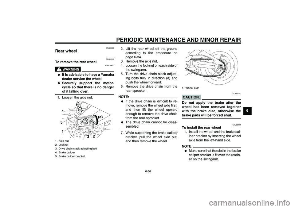
1. Loosen the axle nut.2. Lift the rear wheel off the ground
according to the procedure on
page 6-34.
3. Remove the axle nut.
4. Loosen the locknut on each side of
the swingarm.
5. Turn the drive chain slack adjust-
ing bolts fully in direction (a) and
push the wheel forward.
6. Remove the drive chain from the
rear sprocket.
NOTE:�
If the drive chain is difficult to re-
move, remove the wheel axle first,
and then lift the wheel upward
enough to remove the drive chain
from the rear sprocket.
�
The drive chain cannot be disas-sembled.
7. While supporting the brake caliper
bracket, pull the wheel axle out,
and then remove the wheel.
CAUTION:
ECA11070
Do not apply the brake after the
wheel has been removed together
with the brake disc, otherwise thebrake pads will be forced shut.
EAU39411
To install the rear wheel
1. Install the wheel and the brake cal-
iper bracket by inserting the wheel
axle from the left-hand side.NOTE:�
Make sure that the slot in the brake
caliper bracket is fit over the retain-
er on the swingarm.
1. Axle nut
2. Locknut
3. Drive chain slack adjusting bolt
4. Brake caliper
5. Brake caliper bracket
1. Wheel axle
U2D1E1E0.book Page 36 Friday, September 8, 2006 8:59 AM