Page 85 of 140

8-9
1
2
3
4
5
6
78
9
10
11
a spark plug, a good estimate of the correct torque
is 1/4–1/2 turn past finger tight. However, the spark
plug should be tightened to the specified torque as
soon as possible.
4. Install the spark plug cap.
EBU23341
Transmission oil
The transmission oil level should be checked be-
fore each ride. In addition, the transmission oil
must be changed at the intervals specified in the
periodic maintenance and lubrication chart.
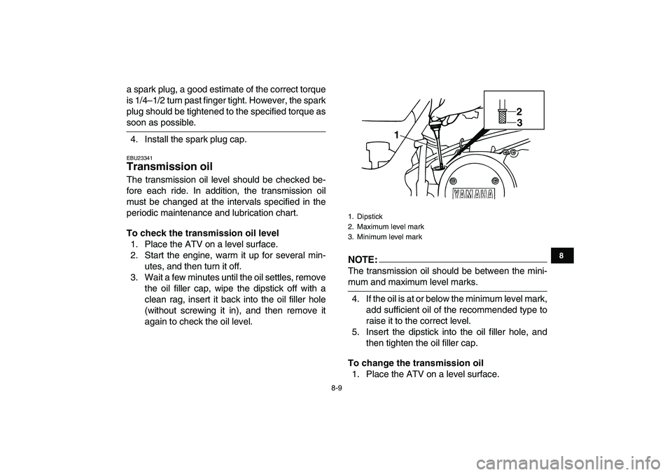
To check the transmission oil level
1. Place the ATV on a level surface.
2. Start the engine, warm it up for several min-
utes, and then turn it off.
3. Wait a few minutes until the oil settles, remove
the oil filler cap, wipe the dipstick off with a
clean rag, insert it back into the oil filler hole
(without screwing it in), and then remove it
again to check the oil level.NOTE:
The transmission oil should be between the mini-
mum and maximum level marks.
4. If the oil is at or below the minimum level mark,
add sufficient oil of the recommended type to
raise it to the correct level.
5. Insert the dipstick into the oil filler hole, and
then tighten the oil filler cap.
To change the transmission oil
1. Place the ATV on a level surface.
1. Dipstick
2. Maximum level mark
3. Minimum level mark
12
3
Page 86 of 140

8-10
1
2
3
4
5
6
78
9
10
11
2. Start the engine, warm it up for several min-
utes, and then turn it off.
3. Place an oil pan under the transmission to col-
lect the used oil.
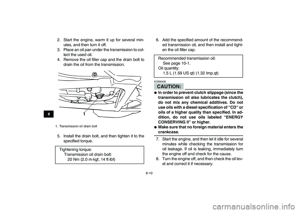
4. Remove the oil filler cap and the drain bolt to
drain the oil from the transmission.
5. Install the drain bolt, and then tighten it to the
specified torque.6. Add the specified amount of the recommend-
ed transmission oil, and then install and tight-
en the oil filler cap.
CAUTION:
ECB00430
�
In order to prevent clutch slippage (since the
transmission oil also lubricates the clutch),
do not mix any chemical additives. Do not
use oils with a diesel specification of “CD” or
oils of a higher quality than specified. In ad-
dition, do not use oils labeled “ENERGY
CONSERVING II” or higher.
�
Make sure that no foreign material enters the
crankcase.
7. Start the engine, and then let it idle for several
minutes while checking the transmission for
oil leakage. If oil is leaking, immediately turn
the engine off and check for the cause.
8. Turn the engine off, and then check the oil lev-
el and correct it if necessary.
1. Transmission oil drain bolt
Tightening torque:
Transmission oil drain bolt:
20 Nm (2.0 m·kgf, 14 ft·lbf)
1
Recommended transmission oil:
See page 10-1.
Oil quantity:
1.5 L (1.59 US qt) (1.32 Imp.qt)
Page 87 of 140
8-11
1
2
3
4
5
6
78
9
10
11
EBU23470
Coolant
The coolant level should be checked before each
ride. In addition, the coolant must be changed at
the intervals specified in the periodic maintenance
and lubrication chart.
EBU23501
To check the coolant level
1. Place the ATV on a level surface.
NOTE:
The coolant level must be checked on a cold en-
gine since the level varies with engine tempera-
ture.
2. Check the coolant level in the coolant reser-
voir.
NOTE:
The coolant should be between the minimum and
maximum level marks.3. If the coolant is at or below the minimum level
mark, remove the seat. (See page 4-11.)
4. Open the coolant reservoir cover.
1. Maximum level mark
2. Minimum level mark
1
2
Page 88 of 140

8-12
1
2
3
4
5
6
78
9
10
11
5. Remove the reservoir cap, add coolant or dis-
tilled water to the maximum level mark, and
then install the reservoir cap.
CAUTION:
ECB00401
�
If coolant is not available, use distilled water
or soft tap water instead. Do not use hard wa-ter or salt water since it is harmful to the en-
gine.
�
If water has been used instead of coolant, re-
place it with coolant as soon as possible,
otherwise the cooling system will not be pro-
tected against frost and corrosion.
�
If water has been added to the coolant, have
a Yamaha dealer check the antifreeze con-
tent of the coolant as soon as possible, oth-
erwise the effectiveness of the coolant will
be reduced.
6. Close the coolant reservoir cover.
7. Install the seat.
NOTE:
If the engine overheats, see page 8-51 for further
instructions.
EBU23521
To change the coolant
WARNING
EWB01890
Wait for the engine and radiator to cool before
removing the radiator cap. You could be
burned by hot fluid and steam blown out under
pressure. Always place a thick rag over the cap
1. Coolant reservoir cover
2. Coolant reservoir cap
Coolant reservoir capacity (up to the maximum
level mark):
0.28 L (0.30 US qt) (0.25 Imp.qt)
1
2
Page 92 of 140

8-16
1
2
3
4
5
6
78
9
10
11
tected against frost and corrosion.
�
If water has been added to the coolant, have
a Yamaha dealer check the antifreeze con-
tent of the coolant as soon as possible, oth-
erwise the effectiveness of the coolant will
be reduced.
12. Install the radiator cap, start the engine, let it
idle for several minutes, and then turn it off.
13. Remove the radiator cap to check the coolant
level in the radiator. If it is low, add sufficient
coolant until it reaches the top of the radiator,
and then install the radiator cap.
14. Start the engine, and then check for coolant
leakage.
NOTE:
If any leakage is found, have a Yamaha dealer
check the cooling system.
15. Install the radiator cover by installing the bolts.
EBU23620
Cleaning the air filter element
The air filter element should be cleaned at the in-
tervals specified in the periodic maintenance and
lubrication chart. Clean the air filter element more
frequently if you are riding in unusually wet or dustyareas.
NOTE:
There is a check hose at the bottom of the air filter
case. If dust or water collects in this hose, empty
the hose and clean the air filter element and air fil-
ter case.
1. Remove the seat. (See page 4-11.)
2. Remove the air filter case cover by unhooking
the holders.
1. Air filter case check hose
1
Page 94 of 140
8-18
1
2
3
4
5
6
78
9
10
11
5. Wash the sponge material gently but thor-
oughly in solvent.
WARNING
EWB01940
Always use parts cleaning solvent to clean the
sponge material. Never use low-flash-point
solvents or gasoline to clean the sponge mate-
rial because the engine could catch fire or ex-
plode.
6. Squeeze the excess solvent out of the sponge
material and let it dry.CAUTION:
ECB00440
Do not twist the sponge material when squeez-
ing it.
7. Check the sponge material and replace it if
damaged.
8. Apply a quality foam air filter oil to the sponge
material.
NOTE:
The sponge material should be wet but not drip-
ping.
9. Pull the sponge material over the air filter ele-
ment frame, and then install the lock plate by
turning it.
1. Sponge material
2. Air filter element frame
3. Air filter element lock plate
1 22
1
3
Page 95 of 140

8-19
1
2
3
4
5
6
78
9
10
11
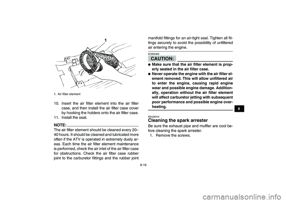
10. Insert the air filter element into the air filter
case, and then install the air filter case cover
by hooking the holders onto the air filter case.
11. Install the seat.
NOTE:
The air filter element should be cleaned every 20–
40 hours. It should be cleaned and lubricated more
often if the ATV is operated in extremely dusty ar-
eas. Each time the air filter element maintenance
is performed, check the air inlet of the air filter case
for obstructions. Check the air filter case rubber
joint to the carburetor fittings and the rubber jointmanifold fittings for an air-tight seal. Tighten all fit-
tings securely to avoid the possibility of unfiltered
air entering the engine.CAUTION:
ECB00460
�
Make sure that the air filter element is prop-
erly seated in the air filter case.
�
Never operate the engine with the air filter el-
ement removed. This will allow unfiltered air
to enter the engine, causing rapid engine
wear and possible engine damage. Addition-
ally, operation without the air filter element
will affect carburetor jetting with subsequent
poor performance and possible engine over-
heating.
EBU28310
Cleaning the spark arrester
Be sure the exhaust pipe and muffler are cool be-
fore cleaning the spark arrester.
1. Remove the screws.
1. Air filter element
1
Page 97 of 140

8-21
1
2
3
4
5
6
78
9
10
11
touching exhaust components.
EBU23992
Changing the carburetor settings
In extremely cold weather, it is necessary to
change the carburetor settings to maintain opti-
mum engine performance and to prevent engine
damage.
WARNING
EWB01990
�
Improperly servicing or adjusting the carbu-
retors could cause them to malfunction with
the possibility of an accident, or the carbure-
tors could leak fuel, which would be a fire
hazard.
�
Carburetor adjustments should only be per-
formed by a Yamaha dealer. Do not attempt
to perform these procedures unless you
have mechanical knowledge and the neces-
sary tools.
�
Do not perform this procedure while the en-
gine is hot. Place a rag under each carbure-
tor to catch any fuel. Wipe up any spilled fuel
completely.
�
After servicing the carburetors, always
check the throttle lever operation before op-erating the ATV to make sure it is working
correctly.
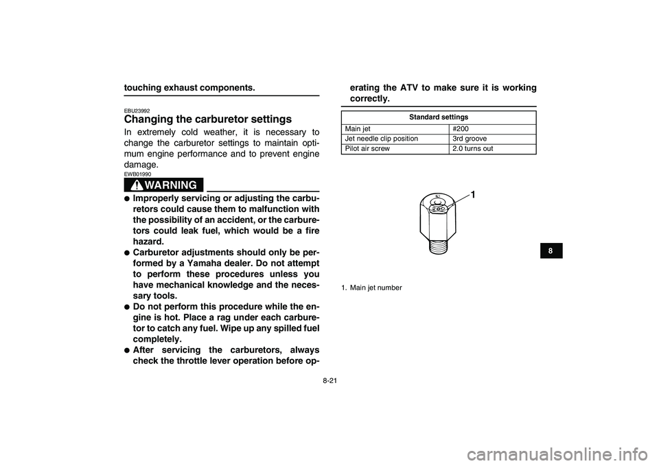
Standard settings
Main jet #200
Jet needle clip position 3rd groove
Pilot air screw 2.0 turns out
1. Main jet number
1