2007 VOLKSWAGEN BEETLE warning
[x] Cancel search: warningPage 104 of 138
Downloaded from www.Manualslib.com manuals search engine th . troductory information and safety warnings & on page 218 First
read and observe e m ·
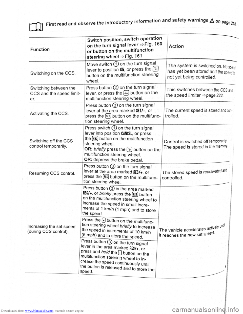
Function
Switching on the CCS .
Switch position, switch op~ration
on the turn signal lever~ Fig. 160
or button on the multifunction
steering wheel ~Fig. 161
Move switch CD on the turn signal
lever to position ON, or press the @
button on the multifunction steering
wheel.
Action
--.
The system is switched on. Nos~
has yet been stored and th e sp eed.
not yet being contro lled .
Switching between the
CCS and the speed limit
er. Press
button
@ on the turn signal
lever,
or press the @ button on the
multifunction steering wheel. This switches between the CCS a
the speed limiter ~page 222.
Activating
the CCS.
Switching off the CCS
control temporarily.
Resuming
CCS control.
Increasing the set speed
(during
CCS control) . Press button
@ on
the turn signal
lever at the area marked
SET/-, or
press the @iJ button on the multifunc
tion steering
wheel.
Press switch CD on the turn signal
lever into position
CANCEL, or press
the
@ button on the multifunction
steering wheel.
OR: briefly press the @0 button on the
multifunction steering wheel.
OR:
depress the brake pedal.
Press button
@ on the turn signal
lever
at the area marked RES/+, or
press the @] button on the multifunc
tion steering wheel.
Press button
@ in the area marked
RES/+, or briefly press the@) button
on the multifunction steering wheel to
increase the speed in
small incre
ments
of 1 km/h (1 mph) and to store
the speed .
The current speed is stored and coo
trolled .
Control is switched off temporarily .
The speed is stored in the memory.
· t d and The stored speed is reactJva e
controlled .
Press the
Q button on the multifunc
tion steering wheel
briefly to increase
the speed
in increments of 1 0 km/h
(5 mph) and to store the speed .
. ntil ct1vely u The vehicle accelerates a
it reaches the new set
speed.
Press button
@on the turn signal
lever in the area marked
RES/+, or
press and hold the Q button on the
multifunction steering wheel to in
crease the speed continuously until
the button is released and to store the
speed .
Page 106 of 138
Downloaded from www.Manualslib.com manuals search engine Speed lirniter
~~~~n~t~ro~d~t~tc~t~io~r~,-----------------------------------------------
hi , h:.1~t r ntains inf nn3tion on th e fo llo wing
subjt 't ~:
lmd indi 1t r I mp . . . . . . . 222
d
limit er . . . . . . . . . . . . . . . 223
h s~ d limit r hel~ t11e driv er n ot to excee d an
individua l ~t r d ~ d wh en driving forwards at
~ t ds f 3~pr im ate ly 30 km /h (20 m ph) and
~1b -
Addition3l Information and w arnings:
• IKm in g g r page 169
• ruls Co ntro l Syst em (CCS) ==-page 218
• dnptive Cruise Con trol (ACC ) ~page 226
• Ac -s ri s, m odifications , re pairs and re newa l
f parts ~ pRge 320
Display & warning and indicator lamp
®
©
' B~K Oot06
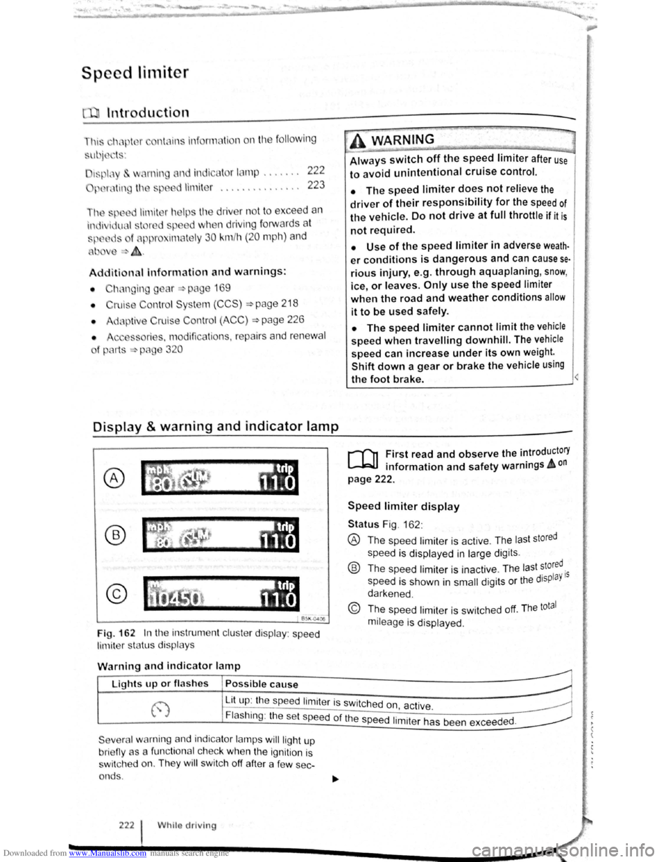
Fig. 162 In th e instrument clu ste r display : speed
limit er sta tus disp lays
·~ ~ ' -
~~~_W_A_R_N_IN_G ________ ~~----~
Always switch off the speed limiter after use
to avoid unintentional cruise control.
• The speed limiter does not relieve the
driver of their responsibility for the speed of
the vehicle. Do not drive at full throttle if it is
not required.
• Use of the speed limiter in adverse weath·
er conditions is dangerous and can cause se
rious injury, e.g. through aquaplaning, snow,
ice, or leaves. Only use the speed limiter
when the road and weather conditions allow
it to be used safely.
• The speed limiter cannot limit the vehicle
speed when travelling downhill. The vehicle
speed can increase under its own weight.
Shift down a gear or brake the vehicle using
the foot brake.
r-f'n First read and observe the introductory
L-JcJ.I information and safety warnings A on
page 222.
Speed limiter display
Status Fig . 162 :
® The spee d limiter is active . The las t stored
speed is displayed in large dig its .
® Th e speed limiter is ina ctive . Th e last stored.
speed is shown in
small digits or the displaY 15
darkened .
© The speed limiter is sw itched off. The total
mileage is displayed .
W
arning and indicator lamp
r~~~fucl,~~~~~---------------------~ Lights up or fl as hes Possible cause
j-~~----~~==~==~~---------------~ ~ L_it;u~p~:~th~e~sp~e:e:d~l:im:i:te:r~is~sw~itc~h~e~d~o~n~~~·~~---------------~ t.,.; :1 , ac 1ve. ~
Flashing : the set speed of the speed 1. .
t h d d
Severa l warning and indicator lamps will ligh t up
bri eny as a func tiona l c h ec k
when the ignition is
s wi tc h ed on. They
wi ll swi tc h off after a few sec
onds .
222 Whilo driving
1m1 er as been excee e .
Page 107 of 138
Downloaded from www.Manualslib.com manuals search engine ~
A WARNING ...
~re to observe illuminated w~rning lan1ps
d text messages can lead to your vehicle
an tt· d breaking down in tra 1C, a n can cause acci-
dent and serious injury.
• Never ignore any Illuminated w arning
lamps or text messages,
CD I'. [
Failure to observe illuminated indicator lamps
and text messages can lead to your vehicle be-
ing damaged.
Operating the speed limiter
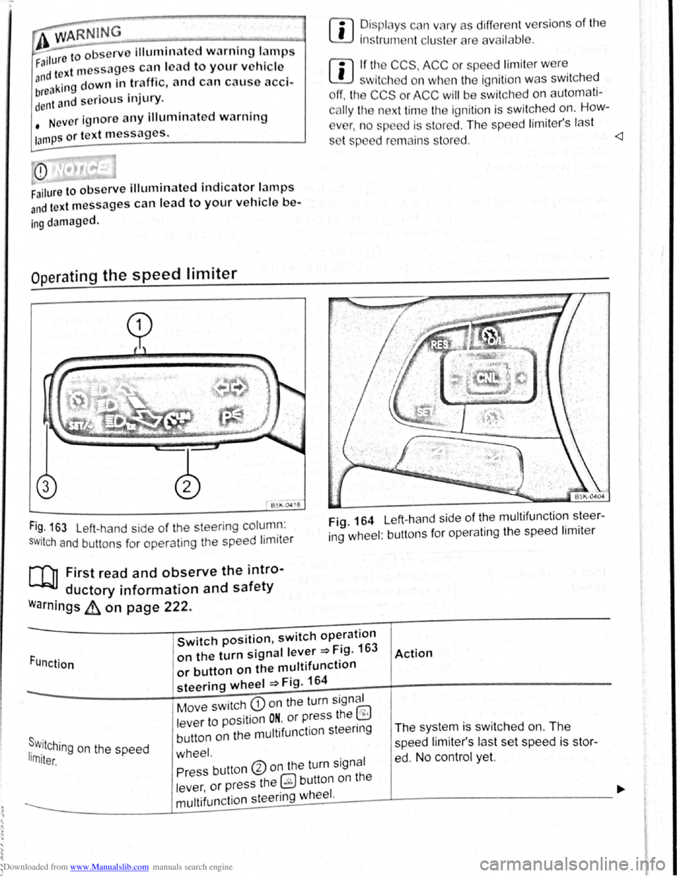
B~l\·04 16
Fi~. 163 Left-hand side of the steering column :
SWitch and buttons for operating the speed limiter
[Q] First read and observe the intro-
ductory information and safety
warnings ~ on page 222.
rn
• ~is plc y c n vary as different vers ions of the
1ns trum nt clu t rare availab le .
rn
• If tl~ CCS, ACC or spe ed limit er w ere
w1tch d on wh n the ignition was switched
ff, the CCS or ACC will be switched on automati
c
lly the n xt time the ignition is switched on. How-
v
r, n o sp d is stored . The speed lim iter's last
s t p d r mains s tored.
ing wheel : buttons for operating the speed limiter
Function
Switch position, switch operation
on the turn signal lever ~Fig. 163
or button on the multifunction
steering wheel ~Fig. 164
Action
s . r w.11Ching on the speed 1rn1ter.
Move switch CD on the turn signal
lever to position
ON. or press the ~
button on the multifunction steenng
wheel.
The system is switched on. The
speed li miter's las t set speed is st or
ed. No control yet. Press button ®on the turn signal
lever ,
or press the 0 button on the
----------------~m~u~lti~fu~n~c~ti~o~n~s~te~e~r~in~g~w~he~e~I~·------J----------------------------~
Page 109 of 138
Downloaded from www.Manualslib.com manuals search engine ... . ·
' '
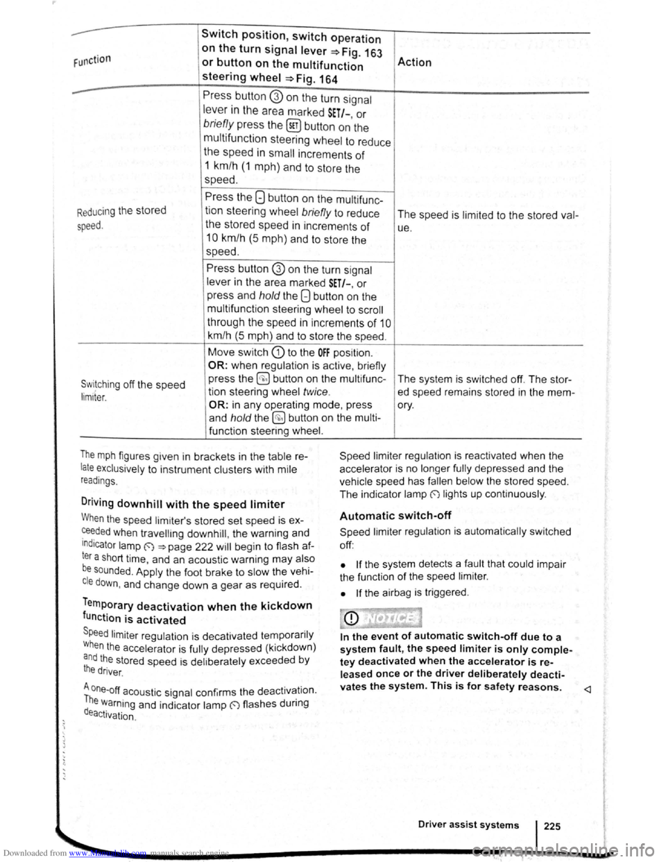
Swit c h posit ion , switch oper ation
F unction
on the turn signal lever=> F ig. 16J
Action or button on the multifunction
steering wheel =>Fig . 164
--Press butto n G) on the turn signal
lever in the area marked S ET/-, or
brie fly pre ss the (sET) button on the
multifu nction
steerin g whe el to reduce
the speed in small increments of
1 km/h ( 1 m ph) a nd to store the
speed.
Press the 8 button on the multi func-
R
educing the stored
tion steering wheel briefly to reduce
The speed is limit e d to the stored val-
speed. the stored speed in increments of ue .
10 km /h (5 m p h) a nd to sto re the
speed.
Press button @ on the turn s ignal
lever i n the a rea marked SET/-, or
p r
ess and hold the Q button on the
m ult ifunctio n stee rin g
wheel t o sc ro ll
t h roug h th e spee d in i ncre m ents
of 1 0
km/h (5 m ph) and to sto re the speed .
Move switc h G) to the OFF position.
OR: when regula tio n is active , briefly
Switching off the speed press
the ~ butto n on th e multifunc -
The system is switched off. The stor-
tion stee rin g wheel twice . ed speed remains stored in the mem -lim1ter.
OR: in any opera tin g m od e, pr es s ory.
a nd
hold th e @ button on the mult i-
f u n ctio n steering wheel.
T
he m ph figures given in bracke ts i n the tab le re
late exclusively to instrument clu sters with mile
r
ead ings.
Driv ing downhill w ith the speed limiter
Speed limi te r regu lat io n is reactivated when the
acce le ra to r is no longe r fully depressed and th e
ve hic le s pee d h as
falle n be low th e s tored speed.
The ind icato r lam p
(') lig hts up continuo usly .
When the speed lim ite r's stored set speed is ex
~e~ded when travellmg downhill, the warn in g a nd
Indicator lamp ~ ~page 22 2 will begi n to flas h af
ter a short tim e, and an aco ustic warnin g may also
be sounded . A pp ly the foot brake to s low the ve hi
cle down, and change down a gear as req uir e d .
Temporary deactivation when the kickdown
function is activated
Speed limite r reg ulatio n is decati va ted te m po rari ly
W he n
the acce le ra to r is fully dep ressed (kickdown)
and the sto red speed is delib erate ly exceede d by
the driver .
A one-off acoustic signal confirms th e deac tivation.
The warning and indicato r lamp (') flashes durin g
deactivation .
. .
Automatic switch-off
Spee d li mi ter regu lat ion is automatically switched
off :
• If the syste m d etects a fa ul t that could im pai r
t he fun ction of th e spee d
limit e r.
•
If t h e airbag is triggered .
In the event of automatic switch-off due to a
system fault, the speed limiter is only comple
tey deactivated when the accelerator is re
leased once or the driver deliberately deacti-
vates the system. This is for safety reasons.
Page 110 of 138
Downloaded from www.Manualslib.com manuals search engine Adaptive cruise control (ACC)
Introduction
Th1s chapter contatns tnformat1on on the followtng
subjects
01spla y. wammg and •nd•catOf lamps 22
Radarsensor 228
Operating adaptive crwse COP r-cY (ACC) ,g
Sw1tch off the adapt ve ens se CO"tro' \ACC
temporanly tn he follow f'l9 S ua~ ""S 3
S I ~~ pec1a dnv ng St ua:10ns ~
The adapt.rve cru'se con··ol (ACC combtn
cruise control and d •s nee control ~
ThG dn r 1
m s ag tn •
rng br l In
page 227
A dd1t1onal informat•on od ar mg :
• Extel'l()( ~ e s ~ pag -
• Vo s agen in!orma~ s rS:e 5
• lnfota.nme t sys:e'n ::. p.aoJ~ 3
• Crurse Co tr04 s.,-s•em CCS :;:) pa,;_ 2i 3
•
Speed I m1ter ~page 222
• Area mon toong SJSte (Front s:s.)
~page 235
• lane departure wa'Tl "'9 sys:e,.., La AssiS~)
~page 240
• AccessofleS mod rca:~ns. repatrS and rene..-aJ
ot parts ~page 320
A WARNING
The intelligent t chnology of th daptive
crul e control (ACC) c nnot ovorcom the
la of phy ic or yst m-r lat d v h1cl hrn.
itation . Cnr I or unlnt ntlon I u of tht
adapttv crui control (ACC) c n c u tiCC•·
dent nd I ad to criou Injury. Th y tem
'i
not ub t
itut forth full cone ntr t1on
of th dn or.
• A
dapt your p d nd d• t ne from tht
ehlclc h nd to uit v i iblltty, w • thcr , r~
nd traffic condition .
• Do not u e th ACC In poor vi 1blllty , on '
steoep or winding ro d , or on ltpp ry ro•d
surfaces e.g . on snow, Ieo , wet road . loo •
chippings or flooded road .
I • Never use the ACC otf-"'oa d or on oon ur·
faced roads. The ACC de ign d for u • on
urface
acle , .g . the tail end of tr ff1c J m . I ..
hicl that ha broken down. or v htcl w.t ,t ·
tng t trnHlc light
1 • Th ACC do not r et t o r on . ant--
mat nd vch cl cro ing or ppr03chm9
r mu t be pr~~r•d to t~t~• '~ 1
htcl (by cc t r ltng ot b,~
------------------------------
Swt eh off lh ACC 1 you u p4t<:t t '~~ ,..,tJJ
s.ensor ha be.tn d mag d . Th• c n h lp ~
pre ent urt.h()r damage. H v• the r dar ,.
realigned
Page 111 of 138
Downloaded from www.Manualslib.com manuals search engine .... ... ' 1)
' ) ....
m The ACC restricts the speed to 160 km/h
W (100 mph). 0
Repair wor k on the radar sensor will require
• ecial knowled ge and tools. Volkswagen rec
~~mends using a Volkswagen dealership for
m If the ACC is active, unfamiliar noises may be
W heard during the automatic braking proce-
this purpose.
dure. Th ese are caused by the braking system.
W this chapte r, do not use the ACC and have
the system checkd by a qualified workshop . V olks
wagen recommends using a Vol kswagen dealer
ship for this purpose .
Display, warning and indicator lamps
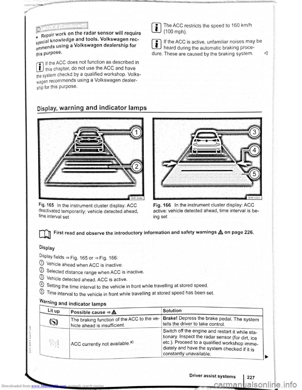
Fig. 165 In the instrument cluster disp lay : ACC
~eactivated temporarily ; vehicle detected ahead,
t1me interval set
BSK-05eJ
Fig. 166 In the instrument cluster display : ACC
active : vehicle detected ahead, time interval is b e
ing set
[Q] First read and observe the introductory information and safety warnings~ on page 226.
Display
D
isplay fields ~Fig. 165 or ~Fig. 166:
G) Vehicle ahea d when ACC is inact ive .
0 Selected distance range when ACC is inactive .
@ Vehicle detected ahead. ACC is active.
@) Setting the time int erval to the vehicle in front while travell ing at stored speed.
® Time interval to the vehicle in front while travell ing at stored speed has been set.
Warning and indicator lamps r--
to--lit up Possible cause ~ 6 Solution
(~) The braking funct ion of the ACC to the ve- Brake!
Depress the brake pedal. The system
t---:. hicle ahead is insu fficient. tells the driver to take control.
Sw itch off the engine and restart it while sta-
ACC currently not availab le. a)
tionary . Inspect the radar sensor (for dirt , ice
• etc.) . Proceed to a qualified workshop imme-
• diately and have the system checked if it is
constantly unavailable .
Driver assist systems 227
-
Page 112 of 138
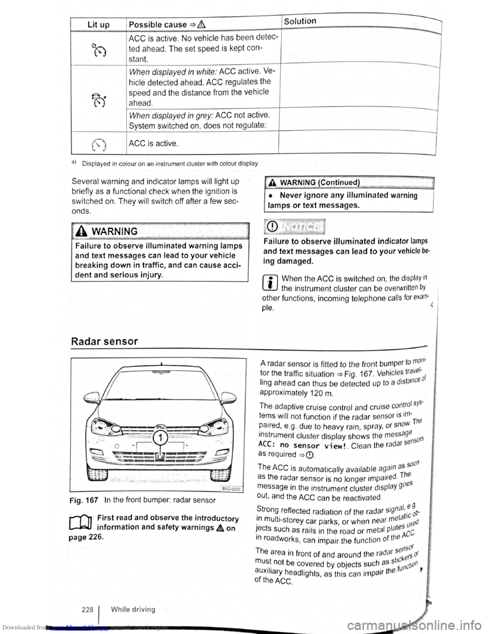
Downloaded from www.Manualslib.com manuals search engine Lit up Possible cause => & Solution
ACC is active . No vehicle has been detec----..
~8 ted ahead . The set speed is kept con-
stant.
When displayed in white: ACC active. Ve---
hicle detected ahead. ACC regulates the
~
speed and the distance from the vehicle
ahead .
-When displayed in grey: ACC not active .
System switched on, does not regulate :
-
(") ACC is active .
a) D isplayed in col our on an ins trum ent clust er w ith colo ur display .
Several warning and indicator lamps will light up
bri efly as a functional check when the ignition is
switched on. They will switch oft after a few sec
onds.
~..,.-"~
A WAR_NING
Failure to observe illuminated warning lamps
and text messages can lead to your vehicle
breaking down in traffic, and can cause acci
dent and serious injury.
Radar sensor
Fig. 167 In the front bumper : radar sensor
r-('n First read and observe the introductory
L-J=JJ information and safety warnings 4 on
page 226.
228 I Whi le driving
•• --;;>
A V'{ARNING (Continued) ~J
• Never ignore any illuminated warning
lamps or text messages.
Failure to observe illuminated indicator lamps
and text messages can lead to your vehicle be·
ing damaged.
r::l When the ACC is switched on, the display in
~ the instrument cluster can be overwritt en by
other functions , incoming telephone calls for exam·~ 1
pie.
to mom · A radar sensor is fitted to the front bump er 1 tor the traffic situation=> Fig. 167 . Vehicl es travc: ·o f
ling ahead can thus be detected up to a dJstan
approximately
120 m .
The adaptive cruise control and cruise
con~rol sys·
tems will not function if the radar sensor is ,m-The
paired , e .g . due to heavy rain, spr ay, or snow.
instrument cluster display shows the me
ssage 50rs
ACC: no sensor view!. Clean the ra d ar s en
as required
=>
· d The as the radar sensor is no longer impa1re ·
message in the instrument cluster display goes
out , and the
ACC can be reactivated .
S ·gnal. e 9 · trong reflected radiation of the radar 5
' 11·c ob-. meta 1 1n mult i-storey car parks or when near used · ' I tes ~ects such as rails in the road or metal P a ACC·
m roadworks . can impair the function of the
sensor
The area in front of and around the radar kers or
mu~t. not be c~vered by objects ~uch. as st'~nction ,
auxJIJary headlights, as this can 1mpa1r the
of the ACC .
Page 115 of 138
Downloaded from www.Manualslib.com manuals search engine ,,nti pttllinfl W• y I not wnllniJI for tdl vo h l-
fltllOI · and cOtllltJJ(' ciOS ·
. g th o clist::tnco lo vo l sett Ill
P d -d O I nclt nt dl st:1n
lhe s t t o n of 5 I v front can b -
vo hl cl In
lnfot in-
n,ent sy stem ,.-;. Pt g 3 1 .
w et road con d ill n , y u llo uld alw y s s t a
:~rger distn nce lh c n wl 1 n drivl11g In dry road con-
ditions.
lt1e following di sta nc s c n b pre-s I cle d :
• very sm 11
• Small
• Medium
• Large
• V ery large
The dis ta nce le ve l to the ve hi cle ahead is se t u sing
the© button on the multifun ction stee ring wheel
~Fig. 168 . The ACC disp la y appears whe n the
button is pressed ~page 227. To se t th e dis ta nce
level, press the (1) button .
When the hig hes t lev el is reached, the distance re
turns to the low est level when th e butt on is press
ed again.
The distance level can also be set usi ng the Q or
8 buttons on the mult ifun ction stee ring wheel im
mediately after the (1) button on the mult ifunction
steering whee l ~Fig. 168 has been pressed .
The~ button and the G and (Dnver ass1stance )
function buttons in the infotainment system can be
used to set the dista nce level that should be selec
ted when the ACC is sw itched on ~page 31 .
Setting the driving programme
In vehicles with Driving Mode Selection , the selec
t~d driving mode can affect the vehicle 's accelera
tion response ~page 248.
The following driving modes can be selected :
• Normal
• Sport
• Eco
In v h' . e lcles Without Driving Mode Selection , the ac-
Celeration response can be affected by the driving
rnode s I IT.Dl ~a e ected by pressing the ~ butto.n and _ the
I . nd @nver assistance ) function buttons 1n the 1nfoa1nrne t n system ~page 31 .
The following conditions can prevent the
adaptive cruise control from reacting:
• If the the acce le rator is depressed.
• If no g ear is selected .
• If the ESC is taking corre ctive action .
• If the driv er h as no t f astened seat belt.
• If there is a fau lt in seve ral brake lights on the
v e hicle or on a traile r with an electrical
connection
to the vehic le .
• If the vehicle is reve rsing .
• If the vehicle is travelling faster than approxi
mately 160 km/h (100 mph).
A WARNING
If you close the gap to a vehicle in front and
the difference in speed between the two vehi
cles is so great that the braking action of the
ACC is insufficient, you are in danger of col
liding with the vehicle in front. You should re
duce the vehicle speed immediately with the
foot brake.
• The ACC may not be able to recognise all
driving situations correctly.
• Leaving your foot on the accelerator will
mean that the ACC will not brake automatical
ly. This is because manual acceleration over
rides the system.
• You should always be prepared to brake
the vehicle yourself.
• Observe country-specific regulations re
garding the minimum distance.
rn
The set speed will be deleted if the ig nition or
the ACC is switched off.
rn
The ACC is automatically deactivated when
the tract ion control system (T CS ) is deactiva-
ted .
rn
In vehicles with a start/stop system, the e n
g ine is switched off automatical ly during the
stat ionary phase of ACC and is then restarted for
moving off.