2007 TOYOTA SIENNA belt
[x] Cancel search: beltPage 2763 of 3000

AIR CONDITIONING – AIR CONDITIONING SYSTEM (for Automatic Air Conditioning Sys-
tem)AC–9
AC
Rear A/C:
No air inlet controlAir inlet damper control servo motor circuitAC-98
Air inlet damper position sensor circuitAC-73
A/C amplifierAC-253
No air outlet controlAir outlet damper position sensor circuitAC-77
Air outlet control servo motor circuitAC-103
A/C amplifierAC-253
Engine idle up does not occur, or is continuousCompressor circuitAC-134
A/C amplifierAC-253
Displayed set temperature value does not match up
with operation of temperature control switchA/C amplifierAC-253
Brightness does not change when rheostat volume or
light control switch is turnedA/C amplifierAC-253
Unable to access the diagnosis mode A/C amplifierAC-253
DTC is not recorded. Set mode is cleared when IG
switch is turned offBack-up power source circuitAC-154
A/C amplifierAC-253
Symptom Suspected Area See page
Whole functions of the A/C system do not operateA/C amplifierAC-253
Rear air conditioning relay circuitAC-142
Rear air conditioning control panel circuitAC-139
Air Flow Control: No blower operationRear blower motor circuitAC-144
A/C amplifierAC-253
Air Flow Control: No blower controlRear blower motor circuitAC-144
A/C amplifierAC-253
Air Flow Control: Insufficient air outRear blower motor circuitAC-144
A/C amplifierAC-253
Temperature Control: Cool air does not come outVolume of refrigerantAC-168
Drive belt tension -
Refrigerant pressureAC-168
Compressor circuitAC-134
Pressure sensor circuitAC-51
Ambient temperature sensor circuitAC-28
Rear evaporator temperature sensor circuitAC-35
A/C amplifierAC-253
Temperature Control: Warm air does not come outRear air mix control servo motor circuitAC-113
Rear air mix damper position sensor circuitAC-85
Ambient temperature sensor circuitAC-28
Rear room temperature sensor circuitAC-39
Rear evaporator temperature sensor circuitAC-35
A/C amplifierAC-253
Heater radiatorAC-187
Temperature Control: Output air is warmer or cooler
than the set temperature or response is slowRear room temperature sensor circuitAC-39
Ambient temperature sensor circuitAC-28
Rear air mix damper position sensor circuitAC-85
Rear air mix control servo motor circuitAC-113
A/C amplifierAC-253
Temperature Control: No temperature control (only
Max. cool or Max. hot)Rear air mix control servo motor circuitAC-113
Rear air mix damper position sensor circuitAC-85
A/C amplifierAC-253 Symptom Suspected Area See page
Page 2768 of 3000

AC–22AIR CONDITIONING – AIR CONDITIONING SYSTEM (for Automatic Air Conditioning Sys-
tem)
AC
B1422/22 Compressor Lock Sensor
Circuit1. A/C compressor (A/C
lock sensor)
2. Compressor drive belt
3. Harness or connector
between compressor and
magnetic clutch (A/C lock
sensor)
4. A/C amplifier
5. CAN communication
system
6. Multiplex
communication system
(BEAN)-AC-47
B1423/23 Pressure Sensor Circuit 1. Pressure sensor
2. Harness or connector
between pressure sensor
and A/C amplifier
3. A/C amplifier
4. Expansion valve
(blocked, stuck)
5. Condenser (blocked,
deterioration of cooling
capacity due to dirt)
6. Cooler dryer (moisture
in the refrigerant cycle
cannot be absorbed)
7. Cooling fan system
(condenser cannot be
cooled down)
8. A/C system (leaks,
blocked)-AC-51
B1424/24
*2Solar Sensor Circuit
(Driver Side)1. Solar sensor
2. Harness or connector
between solar sensor and
A/C amplifier (A/C control
assembly)
3. Harness or connector
between solar sensor and
body ECU
4. A/C amplifier (A/C
control assembly)
5. Body ECUMemorized*3
(8.5 min. or more)
-AC-64
B1431/31 Air Mix Damper Position
Sensor Circuit (Passenger
Side)1. Air mix damper position
sensor
2. A/C amplifier (A/C
control assembly)
3. Harness or connector
between air mix damper
position sensor and A/C
amplifier (A/C control
assembly)Memorized
(1 min. or more)AC-69
B1432/32 Air Inlet Damper Position
Sensor Circuit1. Air inlet damper position
sensor (Air inlet control
servo motor)
2. A/C amplifier (A/C
control assembly)
3. Harness or connector
between air inlet damper
position sensor and A/C
amplifier (A/C control
assembly)Memorized
(1 min. or more)AC-73 DTC Code Detection Item Trouble Area Memory See page
Page 2791 of 3000

AC–48AIR CONDITIONING – AIR CONDITIONING SYSTEM (for Automatic Air Conditioning Sys-
tem)
AC
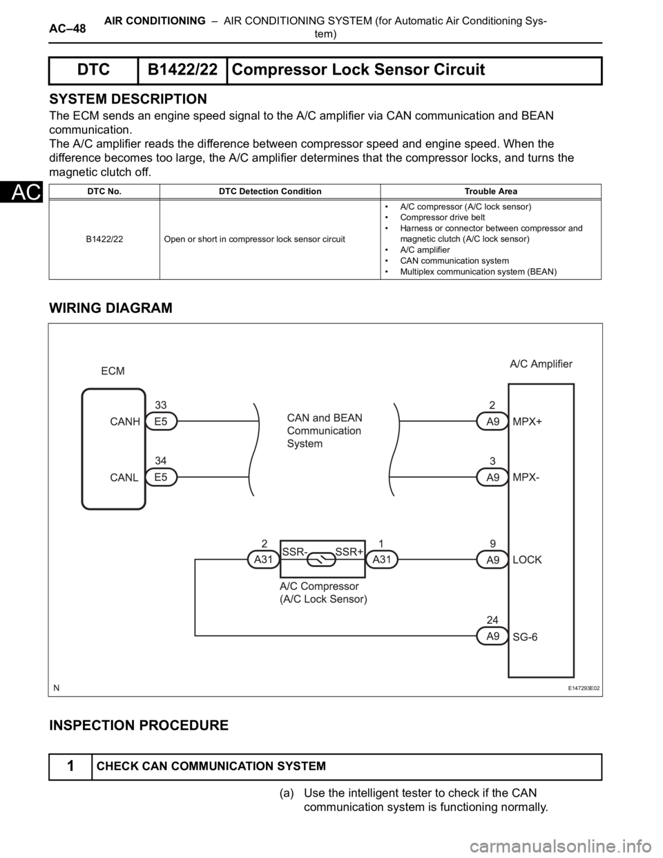
SYSTEM DESCRIPTION
The ECM sends an engine speed signal to the A/C amplifier via CAN communication and BEAN
communication.
The A/C amplifier reads the difference between compressor speed and engine speed. When the
difference becomes too large, the A/C amplifier determines that the compressor locks, and turns the
magnetic clutch off.
WIRING DIAGRAM
INSPECTION PROCEDURE
(a) Use the intelligent tester to check if the CAN
communication system is functioning normally.
DTC B1422/22 Compressor Lock Sensor Circuit
DTC No. DTC Detection Condition Trouble Area
B1422/22 Open or short in compressor lock sensor circuit• A/C compressor (A/C lock sensor)
• Compressor drive belt
• Harness or connector between compressor and
magnetic clutch (A/C lock sensor)
• A/C amplifier
• CAN communication system
• Multiplex communication system (BEAN)
1CHECK CAN COMMUNICATION SYSTEM
E147293E02
Page 2922 of 3000

AC–22AIR CONDITIONING – AIR CONDITIONING SYSTEM (for Automatic Air Conditioning Sys-
tem)
AC
B1422/22 Compressor Lock Sensor
Circuit1. A/C compressor (A/C
lock sensor)
2. Compressor drive belt
3. Harness or connector
between compressor and
magnetic clutch (A/C lock
sensor)
4. A/C amplifier
5. CAN communication
system
6. Multiplex
communication system
(BEAN)-AC-47
B1423/23 Pressure Sensor Circuit 1. Pressure sensor
2. Harness or connector
between pressure sensor
and A/C amplifier
3. A/C amplifier
4. Expansion valve
(blocked, stuck)
5. Condenser (blocked,
deterioration of cooling
capacity due to dirt)
6. Cooler dryer (moisture
in the refrigerant cycle
cannot be absorbed)
7. Cooling fan system
(condenser cannot be
cooled down)
8. A/C system (leaks,
blocked)-AC-51
B1424/24
*2Solar Sensor Circuit
(Driver Side)1. Solar sensor
2. Harness or connector
between solar sensor and
A/C amplifier (A/C control
assembly)
3. Harness or connector
between solar sensor and
body ECU
4. A/C amplifier (A/C
control assembly)
5. Body ECUMemorized*3
(8.5 min. or more)
-AC-64
B1431/31 Air Mix Damper Position
Sensor Circuit (Passenger
Side)1. Air mix damper position
sensor
2. A/C amplifier (A/C
control assembly)
3. Harness or connector
between air mix damper
position sensor and A/C
amplifier (A/C control
assembly)Memorized
(1 min. or more)AC-69
B1432/32 Air Inlet Damper Position
Sensor Circuit1. Air inlet damper position
sensor (Air inlet control
servo motor)
2. A/C amplifier (A/C
control assembly)
3. Harness or connector
between air inlet damper
position sensor and A/C
amplifier (A/C control
assembly)Memorized
(1 min. or more)AC-73 DTC Code Detection Item Trouble Area Memory See page
Page 2959 of 3000

AIR CONDITIONING – COMPRESSOR AND MAGNETIC CLUTCHAC–233
AC
(d) Install the suction hose sub-assembly onto the
compressor and magnetic clutch with the bolt.
Torque: 5.4 N*m (55 kgf*cm, 48 in.*lbf)
3. INSTALL DISCHARGE HOSE SUB-ASSEMBLY
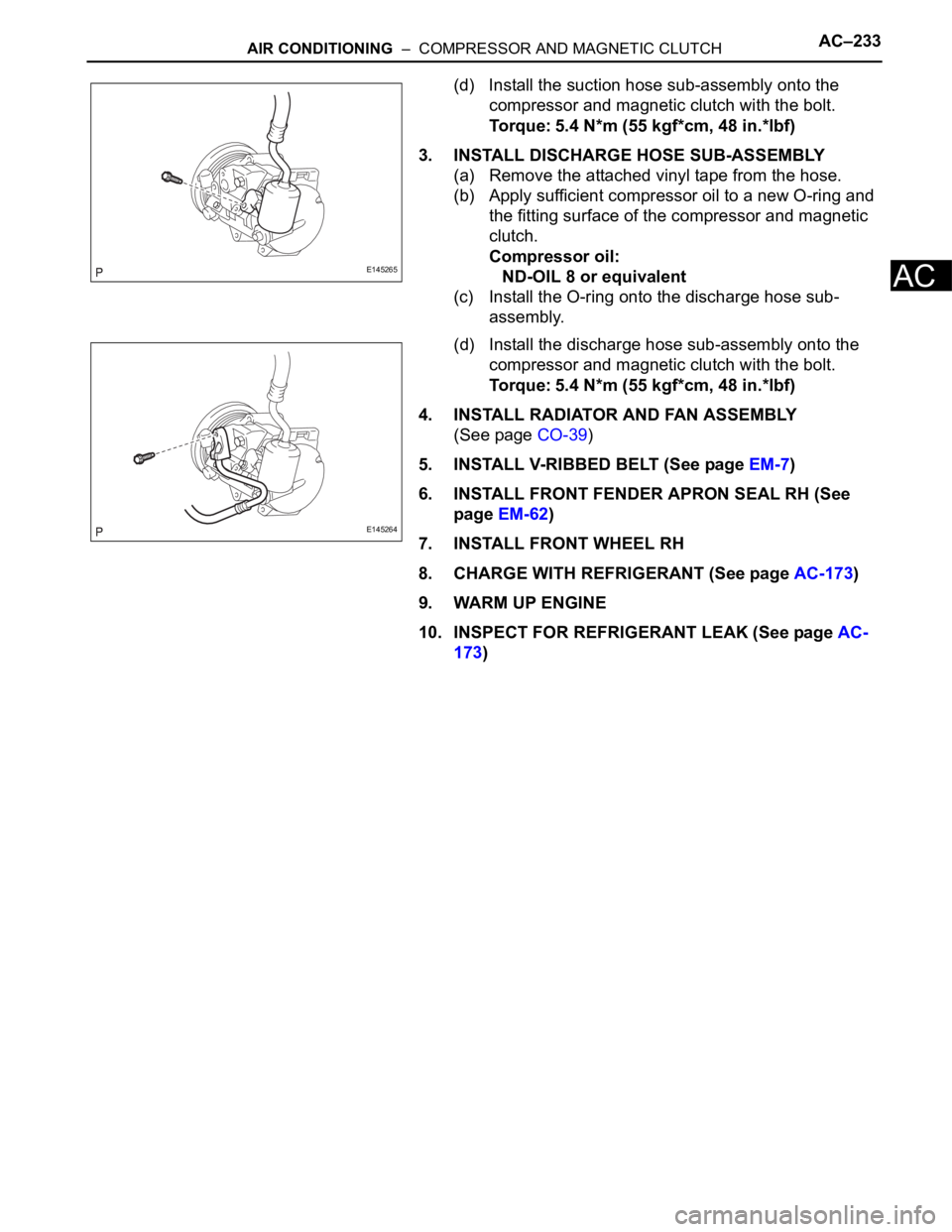
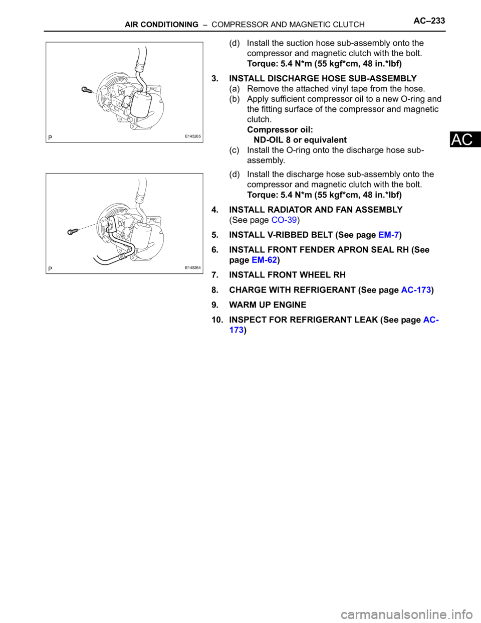
(a) Remove the attached vinyl tape from the hose.
(b) Apply sufficient compressor oil to a new O-ring and
the fitting surface of the compressor and magnetic
clutch.
Compressor oil:
ND-OIL 8 or equivalent
(c) Install the O-ring onto the discharge hose sub-
assembly.
(d) Install the discharge hose sub-assembly onto the
compressor and magnetic clutch with the bolt.
Torque: 5.4 N*m (55 kgf*cm, 48 in.*lbf)
4. INSTALL RADIATOR AND FAN ASSEMBLY
(See page CO-39)
5. INSTALL V-RIBBED BELT (See page EM-7)
6. INSTALL FRONT FENDER APRON SEAL RH (See
page EM-62)
7. INSTALL FRONT WHEEL RH
8. CHARGE WITH REFRIGERANT (See page AC-173)
9. WARM UP ENGINE
10. INSPECT FOR REFRIGERANT LEAK (See page AC-
173)
E145265
E145264
Page 2967 of 3000

AIR CONDITIONING – COMPRESSOR AND MAGNETIC CLUTCHAC–227
AC
REMOVAL
1. RECOVER REFRIGERANT FROM REFRIGERATION
SYSTEM (See page AC-172)
2. REMOVE FRONT WHEEL RH
3. REMOVE FRONT FENDER APRON SEAL RH (See
page EM-26)
4. REMOVE V-RIBBED BELT (See page EM-6)
5. REMOVE RADIATOR AND FAN ASSEMBLY
(See page CO-28)
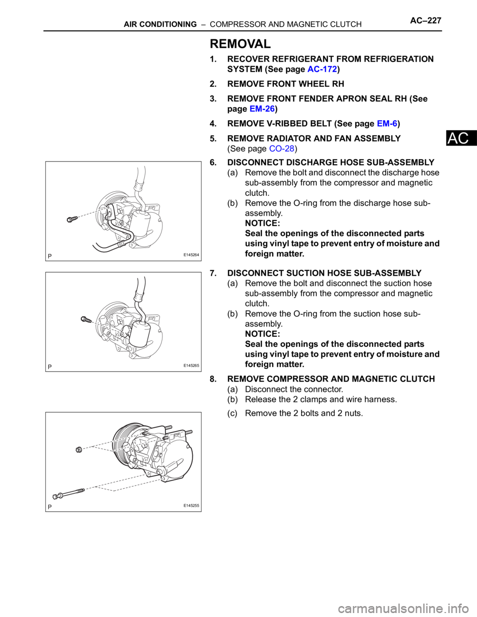
6. DISCONNECT DISCHARGE HOSE SUB-ASSEMBLY
(a) Remove the bolt and disconnect the discharge hose
sub-assembly from the compressor and magnetic
clutch.
(b) Remove the O-ring from the discharge hose sub-
assembly.
NOTICE:
Seal the openings of the disconnected parts
using vinyl tape to prevent entry of moisture and
foreign matter.
7. DISCONNECT SUCTION HOSE SUB-ASSEMBLY
(a) Remove the bolt and disconnect the suction hose
sub-assembly from the compressor and magnetic
clutch.
(b) Remove the O-ring from the suction hose sub-
assembly.
NOTICE:
Seal the openings of the disconnected parts
using vinyl tape to prevent entry of moisture and
foreign matter.
8. REMOVE COMPRESSOR AND MAGNETIC CLUTCH
(a) Disconnect the connector.
(b) Release the 2 clamps and wire harness.
(c) Remove the 2 bolts and 2 nuts.
E145264
E145265
E145255
Page 2973 of 3000

AIR CONDITIONING – COMPRESSOR AND MAGNETIC CLUTCHAC–233
AC
(d) Install the suction hose sub-assembly onto the
compressor and magnetic clutch with the bolt.
Torque: 5.4 N*m (55 kgf*cm, 48 in.*lbf)
3. INSTALL DISCHARGE HOSE SUB-ASSEMBLY
(a) Remove the attached vinyl tape from the hose.
(b) Apply sufficient compressor oil to a new O-ring and
the fitting surface of the compressor and magnetic
clutch.
Compressor oil:
ND-OIL 8 or equivalent
(c) Install the O-ring onto the discharge hose sub-
assembly.
(d) Install the discharge hose sub-assembly onto the
compressor and magnetic clutch with the bolt.
Torque: 5.4 N*m (55 kgf*cm, 48 in.*lbf)
4. INSTALL RADIATOR AND FAN ASSEMBLY
(See page CO-39)
5. INSTALL V-RIBBED BELT (See page EM-7)
6. INSTALL FRONT FENDER APRON SEAL RH (See
page EM-62)
7. INSTALL FRONT WHEEL RH
8. CHARGE WITH REFRIGERANT (See page AC-173)
9. WARM UP ENGINE
10. INSPECT FOR REFRIGERANT LEAK (See page AC-
173)
E145265
E145264
Page 2992 of 3000

SUPPLEMENTAL RESTRAINT SYSTEM – AIRBAG SYSTEMRS–15
RS
SYSTEM DESCRIPTION
1. GENERAL
(a) In conjunction with impact absorbing structure for a
frontal collision, the SRS (Supplemental Restraint
System) driver airbag and front passenger airbag
were designed to supplement seat belts in the event
of a frontal collision in order to help reduce shock to
the head and chest. This system is a 3-sensor type
airbag system to detect the impact during a frontal
collision using the center airbag sensor assembly
and front airbag sensors. It also operates the airbag
system and seat belt pretensioner.
(b) In order to detect the extent of the collision during
the initial stages of the collision in further detail, the
front airbag sensors have been changed from
mechanical type to electrical type deceleration
sensors. Accordingly, the deployment of the driver
airbag and front passenger airbag is controlled in
two stages according to the severity of the impact.
(c) In conjunction with impact absorbing structure for a
side collision, the front seat side airbag and curtain
shield airbag were designed to help reduce shock to
the driver, front passenger, and rear outer
passengers in the event of a side collision or
rollover.
(d) RSCA (Roll Sensing of Curtain Shield Airbags) is
used in order to deploy the curtain shield airbags
and the seat belt pretensioner for the driver and
front passenger, in the event that the vehicle rolls
over.
(e) The curtain shield airbag that helps reduce shock to
the front and rear seat occupants with a single
curtain shield airbag has been adopted. In
conjunction with this system, the side airbag
sensors have been installed at the bottom of the
center pillars and the rear airbag sensors have been
installed at the bottom of the rear pillars
respectively.
(f) In this system, a front side collision is detected by
the side airbag sensors in order to deploy the front
seat side airbag and curtain shield airbag. A rear
side collision is detected by the rear airbag sensors
and the center airbag sensor assembly in order to
deploy the curtain shield airbag.
(g) The center airbag sensor assembly sends the
airbag deployment signal to the ECM through BEAN
(Body Electronics Area Network) and CAN
(Controller Area Network) to operate the fuel pump
control.
(h) The center airbag sensor assembly sends the
airbag deployment signal to the body ECU via a
discrete line to operate collision door lock release
control.