2007 TOYOTA SIENNA coolant temperature
[x] Cancel search: coolant temperaturePage 458 of 3000
ES–1522GR-FE ENGINE CONTROL SYSTEM – SFI SYSTEM
ES
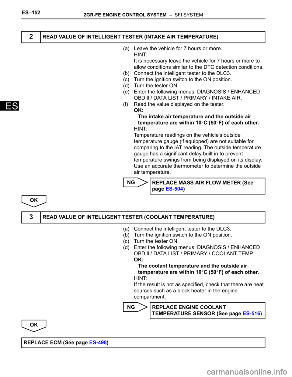
(a) Leave the vehicle for 7 hours or more.
HINT:
It is necessary leave the vehicle for 7 hours or more to
allow conditions similar to the DTC detection conditions.
(b) Connect the intelligent tester to the DLC3.
(c) Turn the ignition switch to the ON position.
(d) Turn the tester ON.
(e) Enter the following menus: DIAGNOSIS / ENHANCED
OBD ll / DATA LIST / PRIMARY / INTAKE AIR.
(f) Read the value displayed on the tester.
OK:
The intake air temperature and the outside air
temperature are within 10
C (50F) of each other.
HINT:
Temperature readings on the vehicle's outside
temperature gauge (if equipped) are not suitable for
comparing to the IAT reading. The outside temperature
gauge has a significant delay built in to prevent
temperature swings from being displayed on its display.
Use an accurate thermometer to determine the outside
air temperature.
NG
OK
(a) Connect the intelligent tester to the DLC3.
(b) Turn the ignition switch to the ON position.
(c) Turn the tester ON.
(d) Enter the following menus: DIAGNOSIS / ENHANCED
OBD ll / DATA LIST / PRIMARY / COOLANT TEMP.
OK:
The coolant temperature and the outside air
temperature are within 10
C (50F) of each other.
HINT:
If the result is not as specified, check that there are heat
sources such as a block heater in the engine
compartment.
NG
OK
2READ VALUE OF INTELLIGENT TESTER (INTAKE AIR TEMPERATURE)
REPLACE MASS AIR FLOW METER (See
page ES-504)
3READ VALUE OF INTELLIGENT TESTER (COOLANT TEMPERATURE)
REPLACE ENGINE COOLANT
TEMPERATURE SENSOR (See page ES-516)
REPLACE ECM (See page ES-498)
Page 468 of 3000

ES–1622GR-FE ENGINE CONTROL SYSTEM – SFI SYSTEM
ES
DESCRIPTION
Refer to DTC P0115 (See page ES-133).
MONITOR DESCRIPTION
The resistance of the ECT sensor varies in proportion to the actual ECT. The ECM supplies a constant
voltage to the sensor and monitors the signal output voltage of the sensor. The signal voltage output
varies according to the changing resistance of the sensor. After the engine is started, the ECT is
monitored through this signal. If the ECT sensor indicates that the engine is not yet warm enough for
closed-loop fuel control, despite a specified period of time having elapsed since the engine was started,
the ECM interprets this as a malfunction in the sensor or cooling system and sets the DTC.
Example:
The ECT is 0
C (32F) at engine start. After 5 minutes running time, the ECT sensor still indicates that the
engine is not warm enough to begin closed-loop fuel (air-fuel ratio feedback) control. The ECM interprets
this as a malfunction in the sensor or cooling system and sets the DTC.
MONITOR STRATEGY
TYPICAL ENABLING CONDITIONS
TYPICAL MALFUNCTION THRESHOLDS
WIRING DIAGRAM
Refer to DTC P0115 (See page ES-134).
DTC P0125Insufficient Coolant Temperature for Closed
Loop Fuel Control
DTC No. DTC Detection Condition Trouble Area
P0125Engine coolant temperature (ECT) does not reach
closed-loop enabling temperature for 20 minutes (this
period varies with engine start ECT)• Cooling system
• Engine coolant temperature sensor
• Thermostat
Related DTCs P0125: Insufficient engine coolant temperature for closed-loop fuel control
Required Sensors / Components (Main) Thermostat, cooling system
Required Sensors / Components (Related) Engine coolant temperature sensor and mass air flow meter
Frequency of Operation Continuous
Duration78 seconds: Engine coolant temperature at engine start -8.34
C (17F) or more
131.3 seconds: Engine coolant temperature at engine start -19.45 to -8.34C (-3 to
17
F)
20 minutes: Engine coolant temperature at engine start less than -19.45
C (-3F)
MIL Operation 2 driving cycles
Sequence of Operation None
The monitor will run whenever these DTCs are not
presentP0100, P0101, P0102, P0103 (MAF) sensor, P0110, P0111, P0112, P0113 (IAT
sensor), P0115, P0116, P0117, P0118 (ECT sensor)
Fuel cut OFF
Engine Running
Time until actual engine coolant temperature reaches
closed-loop fuel control enabling temperature78 seconds or more: Engine coolant temperature at engine start -8.34
C (17F) or
more
131.3 seconds or more: Engine coolant temperature at engine start -19.45 to -8.34
C
(-3 to 17
F)
20 minutes or more: Engine coolant temperature at engine start less than -19.45C (-
3
F)
Page 469 of 3000
2GR-FE ENGINE CONTROL SYSTEM – SFI SYSTEMES–163
ES
INSPECTION PROCEDURE
HINT:
• If any of DTCs P0115, P0116, P0117 or P0118 are set simultaneously with DTC P0125, the Engine
Coolant Temperature (ECT) sensor may have an open or a short circuit. Troubleshoot those DTCs first.
• Read freeze frame data using the intelligent tester. The ECM records vehicle and driving condition
information as freeze frame data the moment a DTC is stored. When troubleshooting, freeze frame
data can be helpful in determining whether the vehicle was running or stopped, whether the engine
was warmed up or not, whether the air-fuel ratio was lean or rich, as well as other data recorded at the
time of a malfunction.
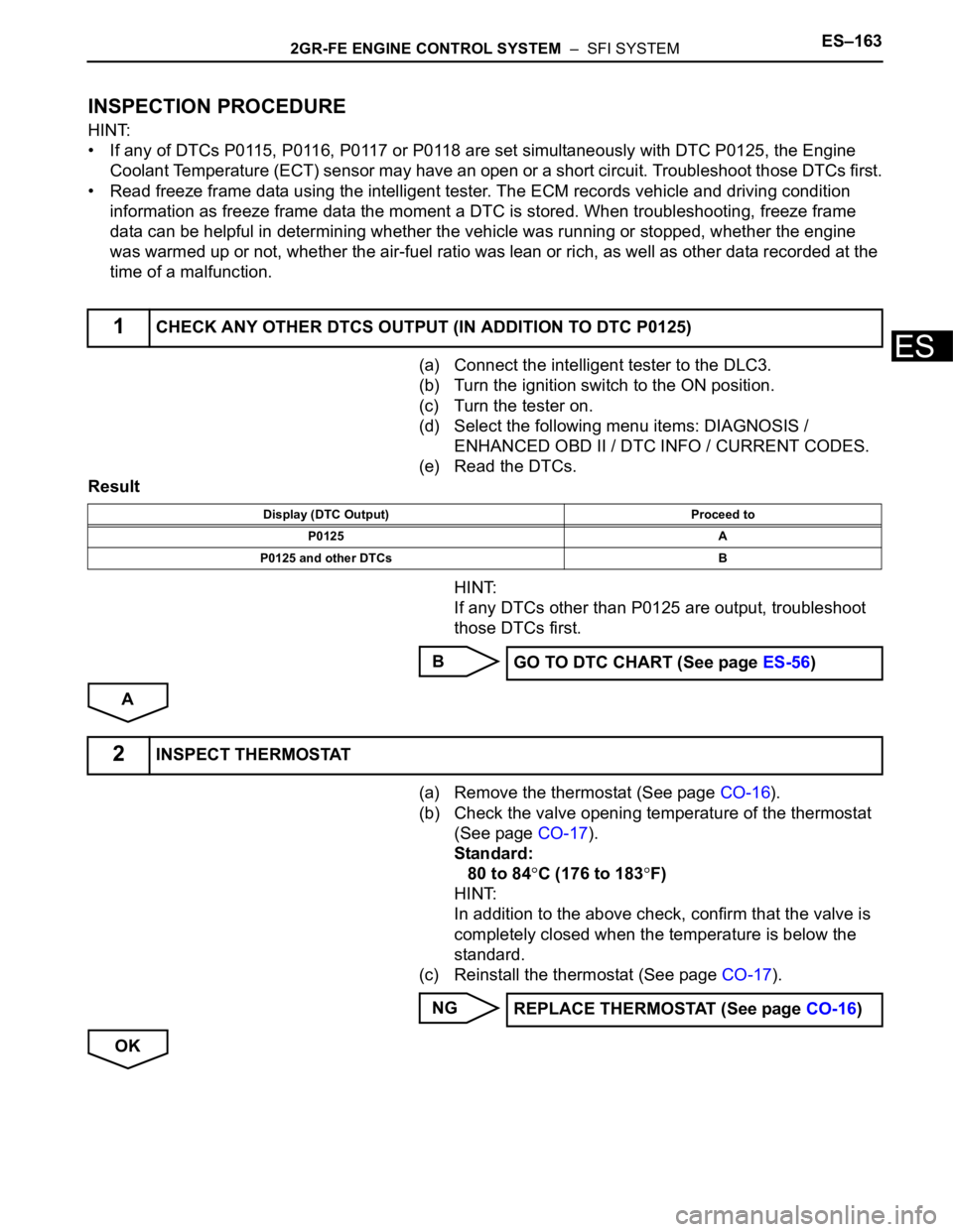
(a) Connect the intelligent tester to the DLC3.
(b) Turn the ignition switch to the ON position.
(c) Turn the tester on.
(d) Select the following menu items: DIAGNOSIS /
ENHANCED OBD II / DTC INFO / CURRENT CODES.
(e) Read the DTCs.
Result
HINT:
If any DTCs other than P0125 are output, troubleshoot
those DTCs first.
B
A
(a) Remove the thermostat (See page CO-16).
(b) Check the valve opening temperature of the thermostat
(See page CO-17).
Standard:
80 to 84
C (176 to 183F)
HINT:
In addition to the above check, confirm that the valve is
completely closed when the temperature is below the
standard.
(c) Reinstall the thermostat (See page CO-17).
NG
OK
1CHECK ANY OTHER DTCS OUTPUT (IN ADDITION TO DTC P0125)
Display (DTC Output) Proceed to
P0125 A
P0125 and other DTCs B
GO TO DTC CHART (See page ES-56)
2INSPECT THERMOSTAT
REPLACE THERMOSTAT (See page CO-16)
Page 470 of 3000
ES–1642GR-FE ENGINE CONTROL SYSTEM – SFI SYSTEM
ES
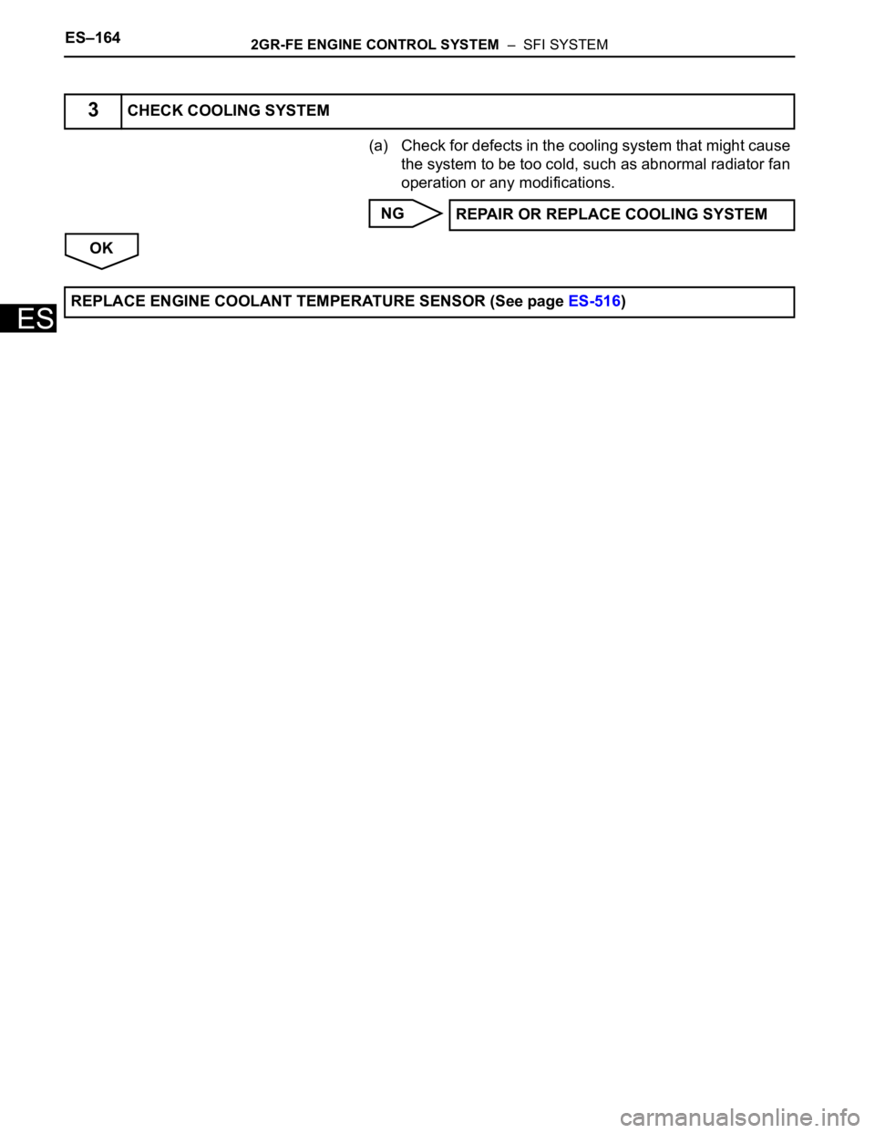
(a) Check for defects in the cooling system that might cause
the system to be too cold, such as abnormal radiator fan
operation or any modifications.
NG
OK
3CHECK COOLING SYSTEM
REPAIR OR REPLACE COOLING SYSTEM
REPLACE ENGINE COOLANT TEMPERATURE SENSOR (See page ES-516)
Page 471 of 3000
2GR-FE ENGINE CONTROL SYSTEM – SFI SYSTEMES–165
ES
HINT:
This DTC relates to the thermostat.
DESCRIPTION
This DTC is set when the Engine Coolant Temperature (ECT) does not reach 75C (167F) despite
sufficient engine warm-up time.
MONITOR DESCRIPTION
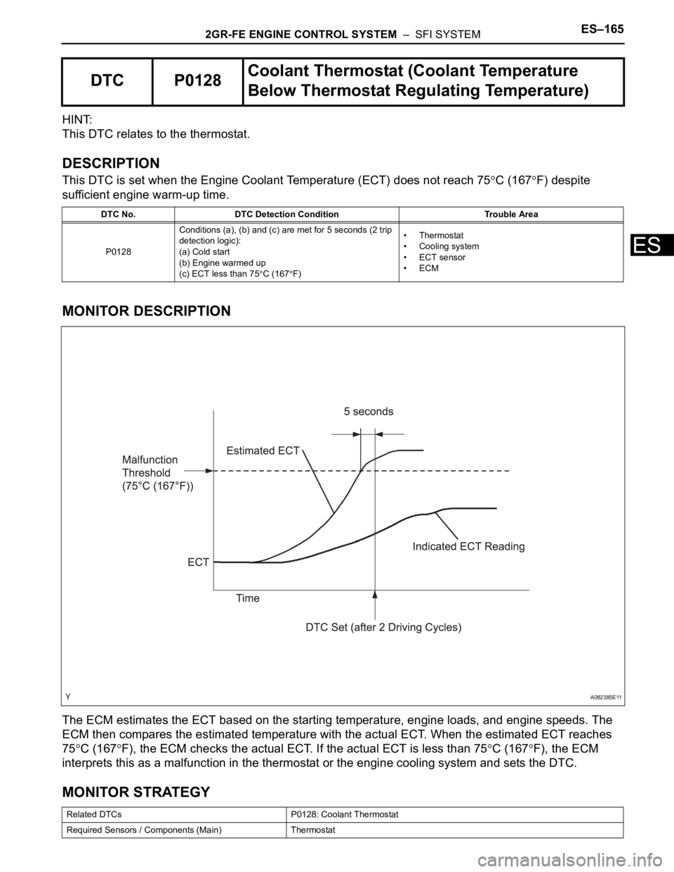
The ECM estimates the ECT based on the starting temperature, engine loads, and engine speeds. The
ECM then compares the estimated temperature with the actual ECT. When the estimated ECT reaches
75
C (167F), the ECM checks the actual ECT. If the actual ECT is less than 75C (167F), the ECM
interprets this as a malfunction in the thermostat or the engine cooling system and sets the DTC.
MONITOR STRATEGY
DTC P0128Coolant Thermostat (Coolant Temperature
Below Thermostat Regulating Temperature)
DTC No. DTC Detection Condition Trouble Area
P0128Conditions (a), (b) and (c) are met for 5 seconds (2 trip
detection logic):
(a) Cold start
(b) Engine warmed up
(c) ECT less than 75
C (167F)•Thermostat
• Cooling system
• ECT sensor
•ECM
Related DTCs P0128: Coolant Thermostat
Required Sensors / Components (Main) Thermostat
A082385E11
Page 472 of 3000

ES–1662GR-FE ENGINE CONTROL SYSTEM – SFI SYSTEM
ES
TYPICAL ENABLING CONDITIONS
TYPICAL MALFUNCTION THRESHOLDS
INSPECTION PROCEDURE
HINT:
Read freeze frame data using the intelligent tester. The ECM records vehicle and driving condition
information as freeze frame data the moment a DTC is stored. When troubleshooting, freeze frame data
can be helpful in determining whether the vehicle was running or stopped, whether the engine was
warmed up or not, whether the air-fuel ratio was lean or rich, as well as other data recorded at the time of
a malfunction.
(a) Connect the intelligent tester to the DLC3.
(b) Turn the ignition switch to the ON position.
(c) Turn the tester on.
(d) Select the following menu items: DIAGNOSIS /
ENHANCED OBD II / DTC INFO / CURRENT CODES.
(e) Read the DTCs.
Required Sensors / Components (Related)Engine Coolant Temperature (ECT) sensor, Intake Air Temperature (IAT) sensor,
Vehicle speed sensor
Frequency of Operation Once per driving cycle
Duration 900 seconds
MIL Operation 2 driving cycles
Sequence of Operation None
The monitor will run whenever these DTCs are not
presentP0010, P0020 (VVT VSV 1, 2), P0011, P0012 (VVT System 1-Advance, Retard),
P0021, P0022 (VVT System 2-Adavance, Retard), P0031, P0032, P0051, P0052 (A/
F Sensor Heater Sensor 1), P0100, P0101, P0102, P0103 (MAF Sensor), P0110,
P0112, P0113 (IAT Sensor), P0115, P0116, P0117, P0118 (ECT Sensor), P0125
(Insufficient ECT for Closed Loop), P0136, P0156 (O2 Sensor 2), P0171, P0172
(Fuel System), P0300, P0301, P0302, P0303, P0304, P0305, P0306 (Misfire),
P0335 (CKP Sensor), P0340 (CMP sensor), P0345 (VVT sensor), P0351, P0352,
P0353, P0354, P0355, P0356 (Ignitor), P0500 (VSS), P2196, P2198(A/F Sensor
(Rationality)), P2A00, P2A03 (A/F Sensor (Slow Response))
Battery voltage 11 V or more
Either of following conditions is met: Condition 1 or 2
1. All of following conditions are met: Conditions (a), (b) and (c)
(a) ECT at engine start - IAT at engine start -15 to 7
C (5 to 45F)
(b) ECT at engine start -10 to 56
C (14 to 133F)
(c) IAT at engine start -10 to 56
C (14 to 133F)
2. All of following conditions are met: Conditions (d), (e) and (f)
(d) ECT at engine start - IAT at engine start More than 7
C (45F)
(e) ECT at engine start 56
C (133F) or less
(f) IAT at engine start -10
C (14F) or more
Accumulated time that vehicle speed is 80 mph (128
km/h) or moreLess than 20 seconds
Duration that all of the following conditions 1 and 2 are
met5 seconds or more
1. Estimated ECT 75
C (167F) or more
2. ECT sensor output Less than 75
C (167F)
1CHECK ANY OTHER DTCS OUTPUT (IN ADDITION TO DTC P0128)
Page 478 of 3000
ES–1722GR-FE ENGINE CONTROL SYSTEM – SFI SYSTEM
ES
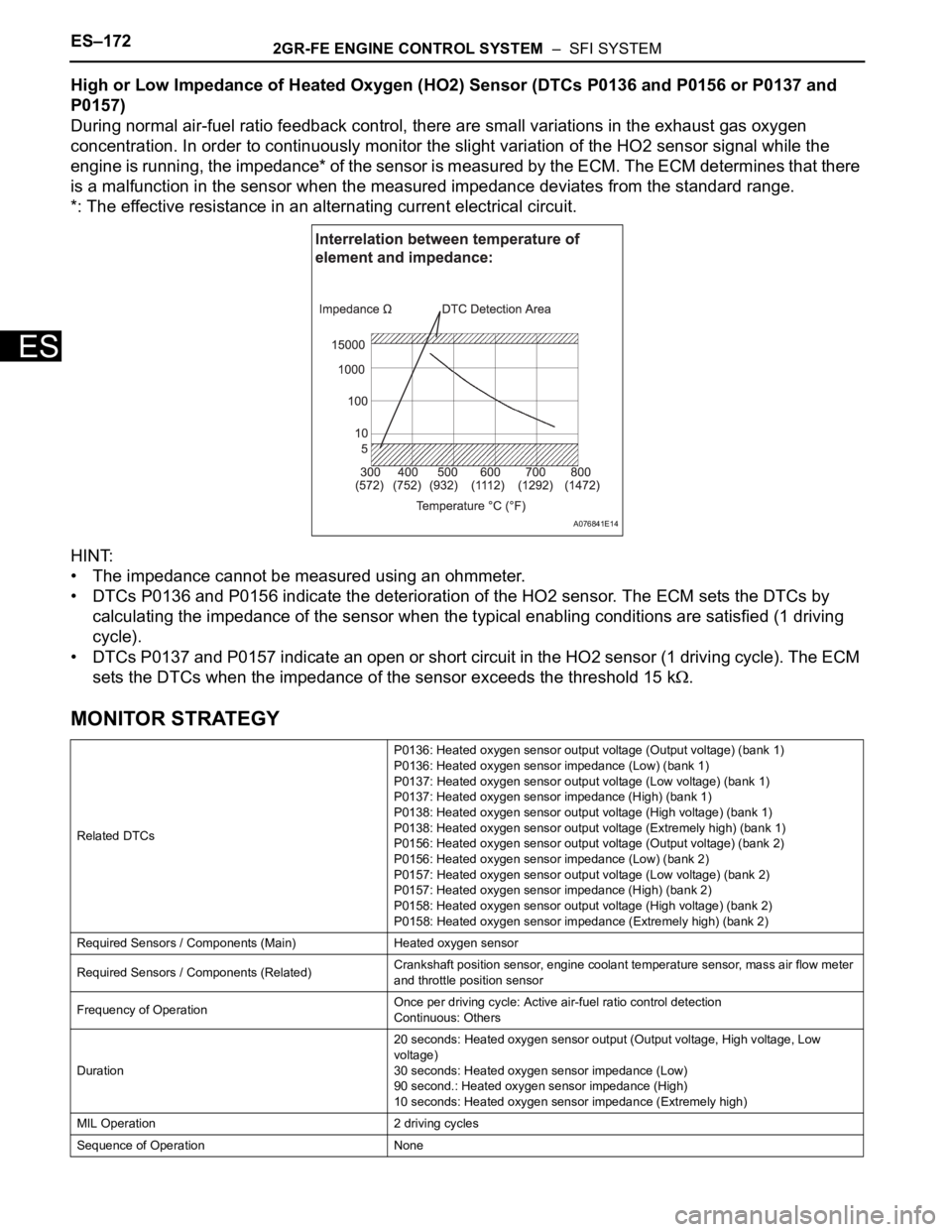
High or Low Impedance of Heated Oxygen (HO2) Sensor (DTCs P0136 and P0156 or P0137 and
P0157)
During normal air-fuel ratio feedback control, there are small variations in the exhaust gas oxygen
concentration. In order to continuously monitor the slight variation of the HO2 sensor signal while the
engine is running, the impedance* of the sensor is measured by the ECM. The ECM determines that there
is a malfunction in the sensor when the measured impedance deviates from the standard range.
*: The effective resistance in an alternating current electrical circuit.
HINT:
• The impedance cannot be measured using an ohmmeter.
• DTCs P0136 and P0156 indicate the deterioration of the HO2 sensor. The ECM sets the DTCs by
calculating the impedance of the sensor when the typical enabling conditions are satisfied (1 driving
cycle).
• DTCs P0137 and P0157 indicate an open or short circuit in the HO2 sensor (1 driving cycle). The ECM
sets the DTCs when the impedance of the sensor exceeds the threshold 15 k
.
MONITOR STRATEGY
Related DTCsP0136: Heated oxygen sensor output voltage (Output voltage) (bank 1)
P0136: Heated oxygen sensor impedance (Low) (bank 1)
P0137: Heated oxygen sensor output voltage (Low voltage) (bank 1)
P0137: Heated oxygen sensor impedance (High) (bank 1)
P0138: Heated oxygen sensor output voltage (High voltage) (bank 1)
P0138: Heated oxygen sensor output voltage (Extremely high) (bank 1)
P0156: Heated oxygen sensor output voltage (Output voltage) (bank 2)
P0156: Heated oxygen sensor impedance (Low) (bank 2)
P0157: Heated oxygen sensor output voltage (Low voltage) (bank 2)
P0157: Heated oxygen sensor impedance (High) (bank 2)
P0158: Heated oxygen sensor output voltage (High voltage) (bank 2)
P0158: Heated oxygen sensor impedance (Extremely high) (bank 2)
Required Sensors / Components (Main) Heated oxygen sensor
Required Sensors / Components (Related)Crankshaft position sensor, engine coolant temperature sensor, mass air flow meter
and throttle position sensor
Frequency of OperationOnce per driving cycle: Active air-fuel ratio control detection
Continuous: Others
Duration20 seconds: Heated oxygen sensor output (Output voltage, High voltage, Low
voltage)
30 seconds: Heated oxygen sensor impedance (Low)
90 second.: Heated oxygen sensor impedance (High)
10 seconds: Heated oxygen sensor impedance (Extremely high)
MIL Operation 2 driving cycles
Sequence of Operation None
A076841E14
Page 479 of 3000

2GR-FE ENGINE CONTROL SYSTEM – SFI SYSTEMES–173
ES
TYPICAL ENABLING CONDITIONS
All:
Heated Oxygen Sensor Output Voltage (Output Voltage, High Voltage and Low Voltage):
Heated Oxygen Sensor Impedance (Low):
Heated Oxygen Sensor Impedance (High):
Heated Oxygen Sensor Output Voltage (Extremely High):
TYPICAL MALFUNCTION THRESHOLDS
Heated Oxygen Sensor Output Voltage (Output voltage):
Heated Oxygen Sensor Output Voltage (Low output voltage):
The monitor will run whenever these DTCs are not
presentP0031, P0032, P0051, P0052 (A/F Sensor Heater Sensor 1), P0100, P0101, P0102,
P0103 (MAF Sensor), P0110, P0112, P0113 (IAT Sensor), P0115, P0116, P0117,
P0118 (ECT Sensor), P0120, P0121, P0122, P0123, P0220, P0222, P0223, P2135
(TP Sensor), P0125 (Insufficient ECT for Closed Loop), P0171, P0172 (Fuel
System), P0300, P0301, P0302, P0303, P0304, P0305, P0306 (Misfire), P0335
(CKP Sensor), P0340 (CMP Sensor), P0500 (VSS), P2196, P2198 (A/F Sensor
(Rationality)), P2A00, P2A03 (A/F Sensor (Slow Response))
Active air-fuel ratio control Performing
Active air-fuel ratio control is performed when the
following conditions are met:-
Battery voltage 11 V or more
Engine coolant temperature 75
C (167F) or more
Idle OFF
Engine RPM Less than 3200 rpm
A/F sensor status Activated
Fuel system status Closed loop
Fuel-cut OFF
Engine load 10 to 70%
Shift position 4th or more
Battery voltage 11 V or more
Estimated HO2S temperature Less than 700
C (1292F)
ECM monitor Completed
DTC P0606 Not set
Battery voltage 11 V or more
Estimated HO2S temperature 450
C (842F) or more
DTC P0606 Not set
Battery voltage 11 V or more
Time after engine start 2 seconds or more
Either of the following conditions is met: 1 or 2
1. All of the following conditions (a), (b) and (c) are met -
(a) Commanded air-fuel ratio 14.3 or less
(b) Rear HO2 sensor voltage 0.21 to 0.59 V
(c) OSC (Oxygen Storage Capacity of Catalyst) 2.0 g (0.0044 lb) or more
2. All of the following conditions (d), (f) and (g) are met. -
(d) Commanded air-fuel ratio 14.9 or more
(f) Rear HO2 sensor voltage 0.21 to 0.59 V
(g) OSC 2.0 g (0.0044 lb) or more
All of the following conditions (a), (b) and (c) are met. -
(a) Commanded air-fuel ratio 14.3 or less