Page 2309 of 3000

TIRE AND WHEEL – TIRE PRESSURE WARNING SYSTEMTW–67
TW
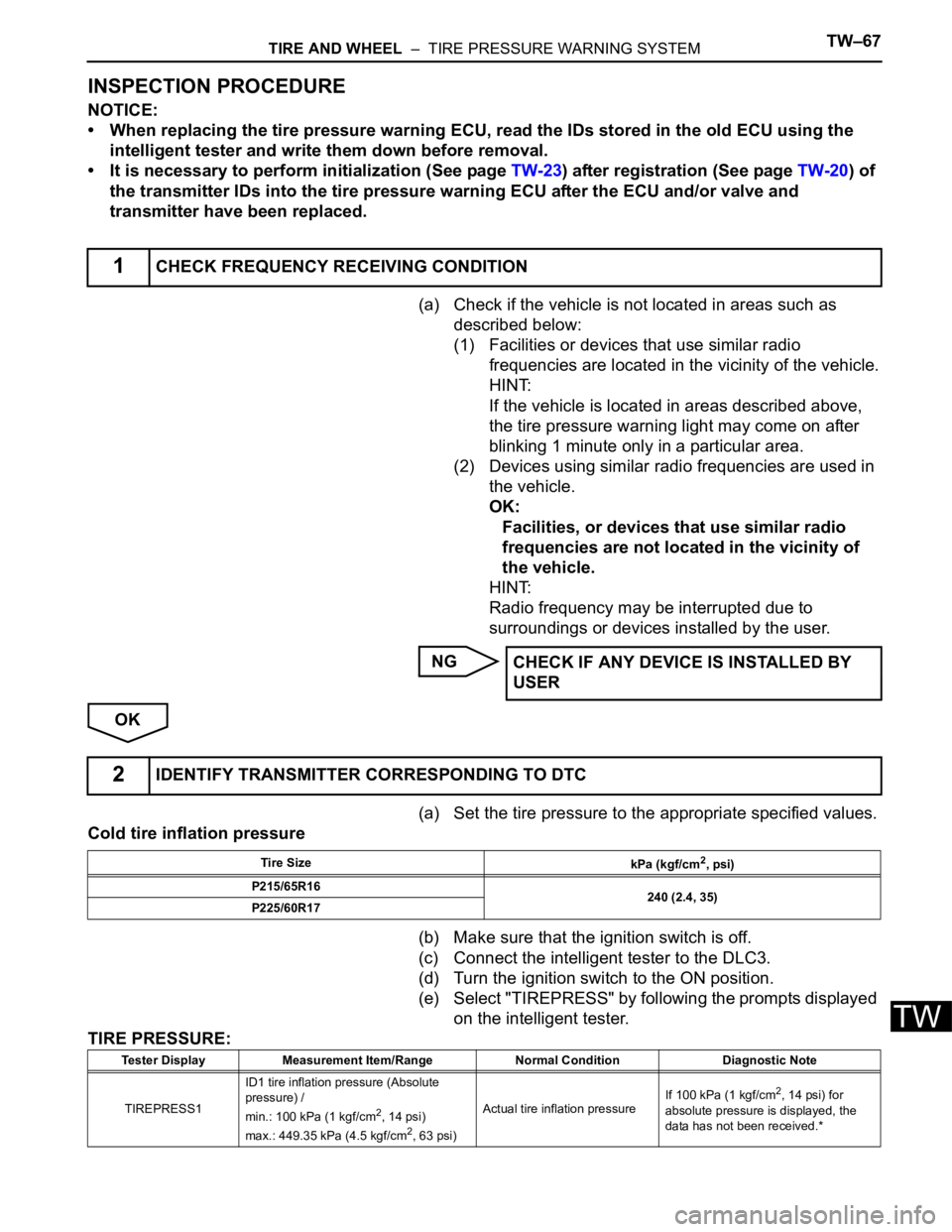
INSPECTION PROCEDURE
NOTICE:
• When replacing the tire pressure warning ECU, read the IDs stored in the old ECU using the
intelligent tester and write them down before removal.
• It is necessary to perform initialization (See page TW-23) after registration (See page TW-20) of
the transmitter IDs into the tire pressure warning ECU after the ECU and/or valve and
transmitter have been replaced.
(a) Check if the vehicle is not located in areas such as
described below:
(1) Facilities or devices that use similar radio
frequencies are located in the vicinity of the vehicle.
HINT:
If the vehicle is located in areas described above,
the tire pressure warning light may come on after
blinking 1 minute only in a particular area.
(2) Devices using similar radio frequencies are used in
the vehicle.
OK:
Facilities, or devices that use similar radio
frequencies are not located in the vicinity of
the vehicle.
HINT:
Radio frequency may be interrupted due to
surroundings or devices installed by the user.
NG
OK
(a) Set the tire pressure to the appropriate specified values.
Cold tire inflation pressure
(b) Make sure that the ignition switch is off.
(c) Connect the intelligent tester to the DLC3.
(d) Turn the ignition switch to the ON position.
(e) Select "TIREPRESS" by following the prompts displayed
on the intelligent tester.
TIRE PRESSURE:
1CHECK FREQUENCY RECEIVING CONDITION
CHECK IF ANY DEVICE IS INSTALLED BY
USER
2IDENTIFY TRANSMITTER CORRESPONDING TO DTC
Tire Size
kPa (kgf/cm2, psi)
P215/65R16
240 (2.4, 35)
P225/60R17
Tester Display Measurement Item/Range Normal Condition Diagnostic Note
TIREPRESS1ID1 tire inflation pressure (Absolute
pressure) /
min.: 100 kPa (1 kgf/cm
2, 14 psi)
max.: 449.35 kPa (4.5 kgf/cm2, 63 psi)Actual tire inflation pressureIf 100 kPa (1 kgf/cm
2, 14 psi) for
absolute pressure is displayed, the
data has not been received.*
Page 2978 of 3000

AIR CONDITIONING – INTEGRATION CONTROL AND PANELAC–255
AC
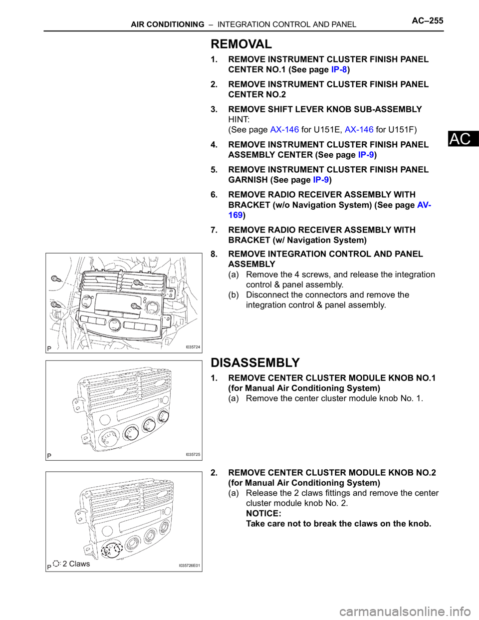
REMOVAL
1. REMOVE INSTRUMENT CLUSTER FINISH PANEL
CENTER NO.1 (See page IP-8)
2. REMOVE INSTRUMENT CLUSTER FINISH PANEL
CENTER NO.2
3. REMOVE SHIFT LEVER KNOB SUB-ASSEMBLY
HINT:
(See page AX-146 for U151E, AX-146 for U151F)
4. REMOVE INSTRUMENT CLUSTER FINISH PANEL
ASSEMBLY CENTER (See page IP-9)
5. REMOVE INSTRUMENT CLUSTER FINISH PANEL
GARNISH (See page IP-9)
6. REMOVE RADIO RECEIVER ASSEMBLY WITH
BRACKET (w/o Navigation System) (See page AV-
169)
7. REMOVE RADIO RECEIVER ASSEMBLY WITH
BRACKET (w/ Navigation System)
8. REMOVE INTEGRATION CONTROL AND PANEL
ASSEMBLY
(a) Remove the 4 screws, and release the integration
control & panel assembly.
(b) Disconnect the connectors and remove the
integration control & panel assembly.
DISASSEMBLY
1. REMOVE CENTER CLUSTER MODULE KNOB NO.1
(for Manual Air Conditioning System)
(a) Remove the center cluster module knob No. 1.
2. REMOVE CENTER CLUSTER MODULE KNOB NO.2
(for Manual Air Conditioning System)
(a) Release the 2 claws fittings and remove the center
cluster module knob No. 2.
NOTICE:
Take care not to break the claws on the knob.
I035724
I035725
I035726E01
Page 2985 of 3000
AC–260AIR CONDITIONING – INTEGRATION CONTROL AND PANEL
AC
INSTALLATION
1. INSTALL INTEGRATION CONTROL AND PANEL
ASSEMBLY
2. INSTALL RADIO RECEIVER WITH BRACKET (w/
Navigation System)
3. INSTALL RADIO RECEIVER WITH BRACKET (w/o
Navigation System)
4. INSTALL INSTRUMENT CLUSTER FINISH PANEL
GARNISH
5. INSTALL INSTRUMENT CLUSTER FINISH PANEL
ASSEMBLY CENTER
6. INSTALL SHIFT LEVER KNOB SUB-ASSEMBLY
7. INSTALL INSTRUMENT CLUSTER FINISH PANEL
CENTER NO.2
8. INSTALL INSTRUMENT CLUSTER FINISH PANEL
CENTER NO.1
Page 2988 of 3000

AIR CONDITIONING – INTEGRATION CONTROL AND PANELAC–255
AC
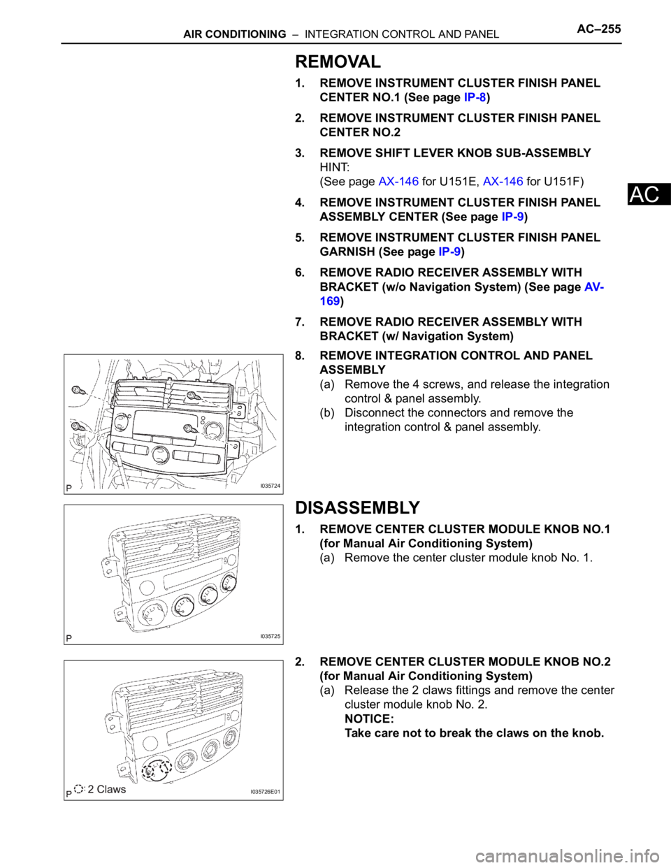
REMOVAL
1. REMOVE INSTRUMENT CLUSTER FINISH PANEL
CENTER NO.1 (See page IP-8)
2. REMOVE INSTRUMENT CLUSTER FINISH PANEL
CENTER NO.2
3. REMOVE SHIFT LEVER KNOB SUB-ASSEMBLY
HINT:
(See page AX-146 for U151E, AX-146 for U151F)
4. REMOVE INSTRUMENT CLUSTER FINISH PANEL
ASSEMBLY CENTER (See page IP-9)
5. REMOVE INSTRUMENT CLUSTER FINISH PANEL
GARNISH (See page IP-9)
6. REMOVE RADIO RECEIVER ASSEMBLY WITH
BRACKET (w/o Navigation System) (See page AV-
169)
7. REMOVE RADIO RECEIVER ASSEMBLY WITH
BRACKET (w/ Navigation System)
8. REMOVE INTEGRATION CONTROL AND PANEL
ASSEMBLY
(a) Remove the 4 screws, and release the integration
control & panel assembly.
(b) Disconnect the connectors and remove the
integration control & panel assembly.
DISASSEMBLY
1. REMOVE CENTER CLUSTER MODULE KNOB NO.1
(for Manual Air Conditioning System)
(a) Remove the center cluster module knob No. 1.
2. REMOVE CENTER CLUSTER MODULE KNOB NO.2
(for Manual Air Conditioning System)
(a) Release the 2 claws fittings and remove the center
cluster module knob No. 2.
NOTICE:
Take care not to break the claws on the knob.
I035724
I035725
I035726E01