Page 810 of 3000

ES–322GR-FE ENGINE CONTROL SYSTEM – SFI SYSTEM
ES
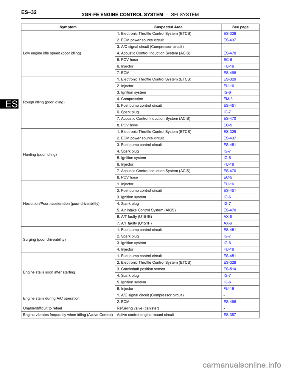
Low engine idle speed (poor idling)1. Electronic Throttle Control System (ETCS)ES-329
2. ECM power source circuitES-437
3. A/C signal circuit (Compressor circuit) -
4. Acoustic Control Induction System (ACIS)ES-470
5. PCV hoseEC-5
6. InjectorFU-16
7. ECMES-498
Rough idling (poor idling)1. Electronic Throttle Control System (ETCS)ES-329
2. InjectorFU-16
3. Ignition systemIG-6
4. CompressionEM-3
5. Fuel pump control circuitES-451
6. Spark plugIG-7
7. Acoustic Control Induction System (ACIS)ES-470
8. PCV hoseEC-5
Hunting (poor idling)1. Electronic Throttle Control System (ETCS)ES-329
2. ECM power source circuitES-437
3. Fuel pump control circuitES-451
4. Spark plugIG-7
5. Ignition systemIG-6
6. InjectorFU-16
7. Acoustic Control Induction System (ACIS)ES-470
8. PCV hoseEC-5
Hesitation/Poor acceleration (poor driveability)1. InjectorFU-16
2. Fuel pump control circuitES-451
3. Ignition systemIG-6
4. Spark plugIG-7
5. Air Intake Control System (AICS)ES-470
6. A/T faulty (U151E)AX-6
7. A/T faulty (U151F)AX-6
Surging (poor driveability)1. Fuel pump control circuitES-451
2. Spark plugIG-7
3. Ignition systemIG-6
4. InjectorFU-16
Engine stalls soon after starting1. Fuel pump control circuitES-451
2. Electronic Throttle Control System (ETCS)ES-329
3. Crankshaft position sensorES-514
4. Spark plugIG-7
5. Ignition systemIG-6
6. InjectorFU-16
Engine stalls during A/C operation1. A/C signal circuit (Compressor circuit) -
2. ECMES-498
Unable/difficult to refuel Refueling valve (canister) -
Engine vibrates frequently when idling (Active Control) Active control engine mount circuitES-397 Symptom Suspected Area See page
Page 881 of 3000
EM–762GR-FE ENGINE MECHANICAL – ENGINE UNIT
EM
DISASSEMBLY
1. REMOVE OIL FILLER CAP SUB-ASSEMBLY
(a) Remove the oil filler cap sub-assembly and oil filler
gasket.
2. REMOVE SPARK PLUG
(a) Remove the spark plugs.
3. REMOVE OIL PAN DRAIN PLUG
(a) Remove the oil pan drain plug and oil pan drain plug
gasket.
4. REMOVE VENTILATION VALVE SUB-ASSEMBLY
(a) Remove the ventilation valve sub-assembly.
5. REMOVE CAMSHAFT POSITION SENSOR
(a) Remove the 4 bolts and 4 camshaft position
sensors.
A129654
A129655
A129656E04
Page 931 of 3000

2GR-FE ENGINE MECHANICAL – ENGINEEM–1
EM
ENGINE
ON-VEHICLE INSPECTION
1. INSPECT ENGINE COOLANT
(a) Inspect the engine coolant (See page CO-1).
2. INSPECT ENGINE OIL
(a) Inspect the engine oil (See page LU-1).
3. INSPECT BATTERY
(a) Inspect the battery (See page CH-5).
4. INSPECT AIR CLEANER FILTER ELEMENT SUB-
ASSEMBLY
(a) Remove the air cleaner filter element sub-assembly.
(b) Visually check that there is no dirt, blockage, and/or
damage to the air cleaner filter element.
HINT:
• If there is any dirt or a blockage in the air cleaner
filter element, clean it with compressed air.
• If any dirt or a blockage remains even after
cleaning the air cleaner filter element with
compressed air, replace it.
5. INSPECT SPARK PLUG
(a) Inspect the spark plugs (See page IG-5).
6. INSPECT VALVE LASH ADJUSTER NOISE
(a) Rev up the engine several times. Check that the
engine does not emit unusual noises.
If unusual noises occur, warm up the engine and
idle it for over 30 minutes. Then repeat this
procedure.
HINT:
If any defects or problems are found during the
inspection above, perform lash adjuster inspection
(See page EM-100).
7. INSPECT IGNITION TIMING
(a) Warm up the engine.
(b) When using the intelligent tester:
Check the ignition timing.
(1) Connect the intelligent tester to the DLC3.
(2) Enter DATA LIST mode with the intelligent
tester.
Ignition timing:
8 to 12
BTDC at idle
HINT:
Refer to the intelligent tester operator's manual
for help when selecting the DATA LIST.
C110200E02
Page 933 of 3000

2GR-FE ENGINE MECHANICAL – ENGINEEM–3
EM
• Switch off all accessories and air
conditioning before connecting the
intelligent tester.
HINT:
Refer to the intelligent tester operator's manual
for further details.
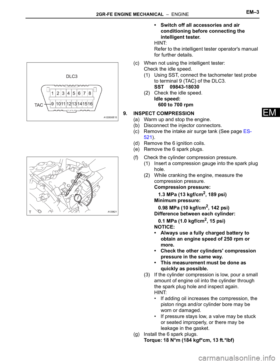
(c) When not using the intelligent tester:
Check the idle speed.
(1) Using SST, connect the tachometer test probe
to terminal 9 (TAC) of the DLC3.
SST 09843-18030
(2) Check the idle speed.
Idle speed:
600 to 700 rpm
9. INSPECT COMPRESSION
(a) Warm up and stop the engine.
(b) Disconnect the injector connectors.
(c) Remove the intake air surge tank (See page ES-
521).
(d) Remove the 6 ignition coils.
(e) Remove the 6 spark plugs.
(f) Check the cylinder compression pressure.
(1) Insert a compression gauge into the spark plug
hole.
(2) While cranking the engine, measure the
compression pressure.
Compression pressure:
1.3 MPa (13 kgf/cm
2, 189 psi)
Minimum pressure:
0.98 MPa (10 kgf/cm
2, 142 psi)
Difference between each cylinder:
0.1 MPa (1.0 kgf/cm
2, 15 psi)
NOTICE:
• Always use a fully charged battery to
obtain an engine speed of 250 rpm or
more.
• Check the other cylinders' compression
pressure in the same way.
• This measurement must be done as
quickly as possible.
(3) If the cylinder compression is low, pour a small
amount of engine oil into the cylinder through
the spark plug hole and inspect again.
HINT:
• If adding oil increases the compression, the
piston rings and/or cylinder bore may be
worn or damaged.
• If pressure stays low, a valve may be stuck
or seated improperly, or there may be
leakage in the gasket.
(g) Install the 6 spark plugs.
Torque: 18 N*m (184 kgf*cm, 13 ft.*lbf)
A122830E15
A129621
Page 978 of 3000
2GR-FE ENGINE MECHANICAL – ENGINE UNITEM–169
EM
66. INSTALL CAMSHAFT TIMING OIL CONTROL VALVE
ASSEMBLY
(a) Install the 4 camshaft timing oil control valves with
the 4 bolts.
Torque: 10 N*m (102 kgf*cm, 7 ft.*lbf)
67. INSTALL CAMSHAFT POSITION SENSOR
(a) Install the 4 camshaft position sensors with the 4
bolts.
Torque: 10 N*m (102 kgf*cm, 7 ft.*lbf)
68. INSTALL VENTILATION VALVE SUB-ASSEMBLY
(a) Apply adhesive around the ventilation valve sub-
assembly.
Adhesive:
Toyota Genuine Adhesive 1324, Three Bond
1324 or equivalent
(b) Install the ventilation valve sub-assembly.
Torque: 27 N*m (275 kgf*cm, 20 ft.*lbf)
69. INSTALL SPARK PLUG
(a) Install the 6 spark plugs.
Torque: 18 N*m (184 kgf*cm, 13 ft.*lbf)
70. INSTALL OIL FILLER CAP SUB-ASSEMBLY
(a) Install a new oil filler gasket.
(b) Install the oil filler cap sub-assembly.
A129662E07
A129656E04
A129655
Page 1023 of 3000
EM–762GR-FE ENGINE MECHANICAL – ENGINE UNIT
EM
DISASSEMBLY
1. REMOVE OIL FILLER CAP SUB-ASSEMBLY
(a) Remove the oil filler cap sub-assembly and oil filler
gasket.
2. REMOVE SPARK PLUG
(a) Remove the spark plugs.
3. REMOVE OIL PAN DRAIN PLUG
(a) Remove the oil pan drain plug and oil pan drain plug
gasket.
4. REMOVE VENTILATION VALVE SUB-ASSEMBLY
(a) Remove the ventilation valve sub-assembly.
5. REMOVE CAMSHAFT POSITION SENSOR
(a) Remove the 4 bolts and 4 camshaft position
sensors.
A129654
A129655
A129656E04
Page 1116 of 3000
2GR-FE ENGINE MECHANICAL – ENGINE UNITEM–169
EM
66. INSTALL CAMSHAFT TIMING OIL CONTROL VALVE
ASSEMBLY
(a) Install the 4 camshaft timing oil control valves with
the 4 bolts.
Torque: 10 N*m (102 kgf*cm, 7 ft.*lbf)
67. INSTALL CAMSHAFT POSITION SENSOR
(a) Install the 4 camshaft position sensors with the 4
bolts.
Torque: 10 N*m (102 kgf*cm, 7 ft.*lbf)
68. INSTALL VENTILATION VALVE SUB-ASSEMBLY
(a) Apply adhesive around the ventilation valve sub-
assembly.
Adhesive:
Toyota Genuine Adhesive 1324, Three Bond
1324 or equivalent
(b) Install the ventilation valve sub-assembly.
Torque: 27 N*m (275 kgf*cm, 20 ft.*lbf)
69. INSTALL SPARK PLUG
(a) Install the 6 spark plugs.
Torque: 18 N*m (184 kgf*cm, 13 ft.*lbf)
70. INSTALL OIL FILLER CAP SUB-ASSEMBLY
(a) Install a new oil filler gasket.
(b) Install the oil filler cap sub-assembly.
A129662E07
A129656E04
A129655
Page 1311 of 3000
2GR-FE IGNITION – IGNITION COIL AND SPARK PLUGIG–9
IG
REMOVAL
1. DISCONNECT CABLE FROM NEGATIVE BATTERY
TERMINAL
2. DRAIN ENGINE COOLANT
3. REMOVE FRONT WIPER ARM HEAD CAP (See page
WW-4)
4. REMOVE FRONT WIPER ARM RH (See page WW-4)
5. REMOVE FRONT WIPER ARM LH (See page WW-4)
6. REMOVE COWL TOP VENTILATOR LOUVER SUB-
ASSEMBLY (See page WW-4)
7. REMOVE WINDSHIELD WIPER MOTOR AND LINK
ASSEMBLY (See page WW-4)
8. REMOVE NO. 1 COWL TOP TO COWL BRACE INNER
(See page FU-13)
9. REMOVE COWL TOP PANEL SUB-ASSEMBLY
OUTER FRONT (See page FU-13)
10. REMOVE NO. 1 ENGINE UNDER COVER
11. REMOVE V-BANK COVER SUB-ASSEMBLY (See
page EM-28)
12. REMOVE AIR CLEANER CAP SUB-ASSEMBLY (See
page FU-13)
13. REMOVE INTAKE AIR SURGE TANK ASSEMBLY
(See page FU-14)
14. REMOVE NO. 1 SURGE TANK STAY
(a) Remove the 2 bolts and nut and disconnect the 2
harness clamps.
(b) Remove the bolt and No. 1 surge tank stay.
A161840
A134967