Page 271 of 3000

NS–10NAVIGATION – NAVIGATION SYSTEM
NS
CAUTION:
Do not look directly at the laser pickup because
the radio and navigation assembly (built-in
navigation ECU) uses an invisible laser beam.
Be sure to only operate the navigation system
as instructed.
4. CD (Compact Disc) player outline
(a) A compact disc player uses a laser pickup to read
digital signals recorded on a compact disc (CD). By
converting the digital signals to analog, it can play
music and other things.
NOTICE:
• Do not disassemble any part of the CD player.
• Do not apply oil to the CD player.
• Do not insert anything but a CD into the CD
player.
CAUTION:
Do not look directly at the laser pickup because
the CD player uses an invisible laser beam. Be
sure to only operate the player as instructed.
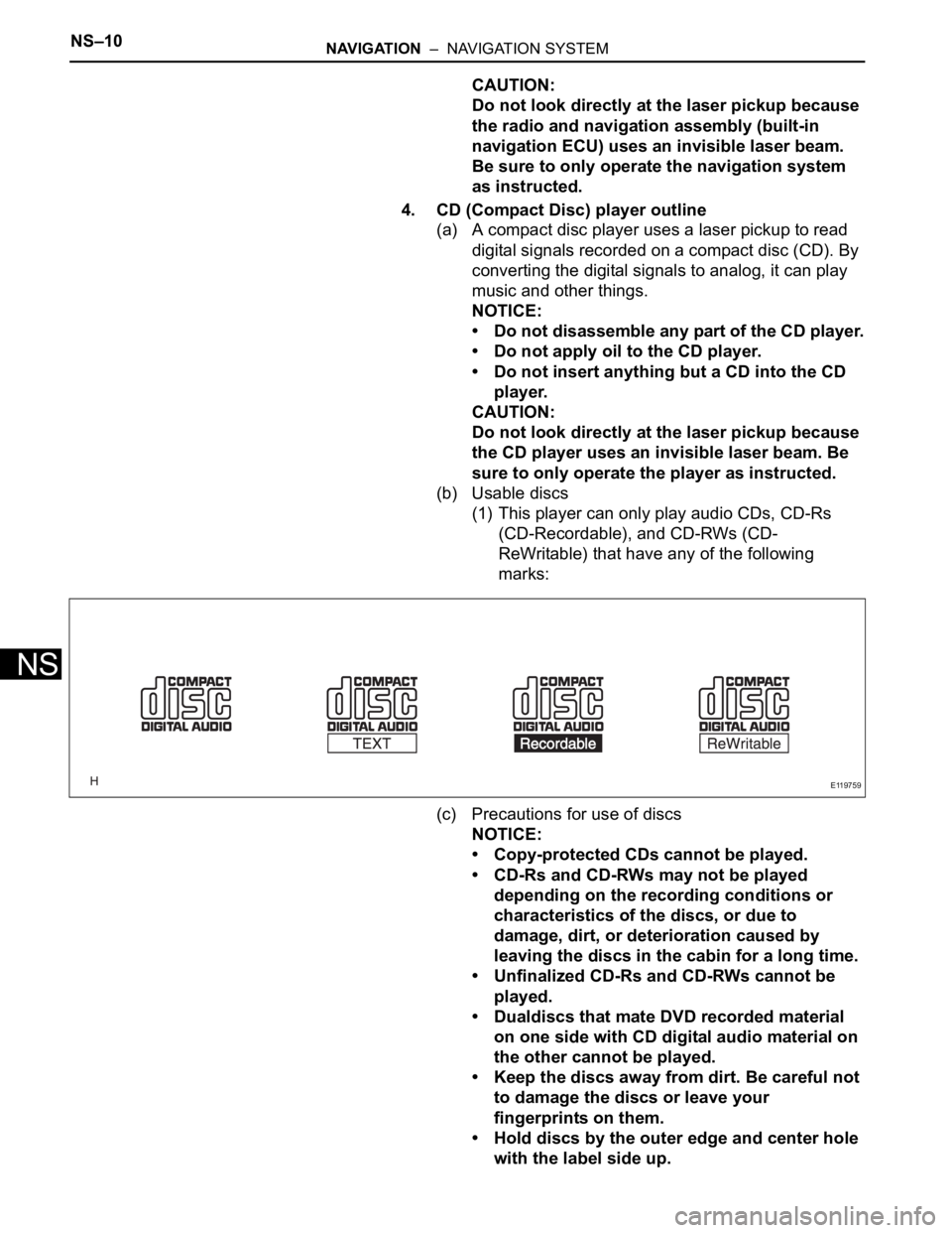
(b) Usable discs
(1) This player can only play audio CDs, CD-Rs
(CD-Recordable), and CD-RWs (CD-
ReWritable) that have any of the following
marks:
(c) Precautions for use of discs
NOTICE:
• Copy-protected CDs cannot be played.
• CD-Rs and CD-RWs may not be played
depending on the recording conditions or
characteristics of the discs, or due to
damage, dirt, or deterioration caused by
leaving the discs in the cabin for a long time.
• Unfinalized CD-Rs and CD-RWs cannot be
played.
• Dualdiscs that mate DVD recorded material
on one side with CD digital audio material on
the other cannot be played.
• Keep the discs away from dirt. Be careful not
to damage the discs or leave your
fingerprints on them.
• Hold discs by the outer edge and center hole
with the label side up.
E119759
Page 275 of 3000

NS–14NAVIGATION – NAVIGATION SYSTEM
NS
(b) Purpose:
Recently, car audio systems have rapidly developed
and the functions have vastly changed. The
conventional car audio system is being integrated
with multi-media interfaces similar to those in
navigation systems. At the same time, customers
are demanding higher quality from their audio
systems. This is merely an overview of the
standardization background. The specific purposes
are as follows:
(1) To solve sound problems, etc. caused by using
components of different manufacturers through
signal standardization.
(2) To allow each manufacturer to concentrate on
developing products they do best. From this,
reasonably priced products can be produced.
HINT:
• If a short to +B or short to ground is detected
in the AVC-LAN circuit, communication is
interrupted and the audio system will stop
functioning.
• If an audio system is equipped with a
navigation system, the multi-display unit acts
as the master unit.
If the navigation system is not equipped, the
audio head unit acts as the master unit
instead. If the radio and navigation assembly
is equipped, it is the master unit.
• The radio and navigation assembly contains
a resistor that is necessary to enable
communication on the different AVC-LAN
circuits.
• The car audio system with an AVC-LAN
circuit has a diagnostic function.
• Each component has a specified number (3-
digit) called a physical address. Each function
has a number (2-digit) called a logical
address.
7. Communication system outline
(a) Components of the navigation system communicate
with each other via the AVC-LAN.
(b) The radio and navigation assembly has enough
resistance (60 to 80
) necessary for
communication.
(c) If a short circuit or open circuit occurs in the AVC-
LAN circuit, communication is interrupted and the
navigation system will stop functioning.
8. Diagnostic function outline
(a) The audio system has a diagnostic function (the
result is indicated on the master unit).
(b) A 3-digit hexadecimal component code (physical
address) is allocated to each component on the
AVC-LAN. Using this code, the component in the
diagnostic function can be displayed.
Page 276 of 3000
NAVIGATION – NAVIGATION SYSTEMNS–15
NS
9. Bluetooth outline
(a) Bluethooth is a trademark owned by Bluetooth SIG.
Inc.
(b) Bluetooth is a new wireless connection technology
that uses the 2.4 GHz frequency band. This makes
it possible to connect a cellular phone (Bluetooth
compatible phone
*1) to the radio and navigation
assembly (the Bluetooth system is built in), and use
the handsfree function of the cellular phone, even if
it is in a pocket or bag. As a result, it is not
necessary to use a connector attached directly to
the cellular phone.
*1: Some versions of Bluetooth compatible cellular
phones may not function.
HINT:
The communication performance of Bluetooth may
vary depending on obstructions or radio wave
conditions between communication devices,
electromagnetic radiation, communication device
sensitivity, or antenna capacity.
E100921
E121227E01
Page 277 of 3000

PARK ASSIST / MONITORING – REAR VIEW MONITOR SYSTEMPM–3
PM
SYSTEM DESCRIPTION
1. GENERAL
(a) To assist the driver with parking the vehicle by
displaying an image of the area behind the vehicle,
this system has a television camera mounted on the
luggage compartment door. The system displays
the image on the radio and navigation assembly.
(b) This system consists of the following components:
(1) Radio and navigation assembly
(2) Television camera assembly
(c) This system is equipped with a self-diagnosis
system, which is operated on a dedicated window
that appears on the display panel, just as in the
navigation system.
2. FUNCTION OF COMPONENTS
(a) The radio and navigation assembly controls the
system by using information from the following
components:
3. OPERATION EXPLANATION
(a) The radio and navigation assembly receives the R
position signal from the park / neutral position switch
when the shift lever is moved to the R position. After
receiving the R position signal, the radio and
navigation assembly switches from the navigation
system to the rear view monitor system.
4. NOTES FOR REAR VIEW MONITOR
(a) Notes for the rear view monitor.
(1) The rear view monitor may not function properly
if subjected to a severe blow by any hard object.
(2) Do not "scrub" the cover part of the camera
(resin made). Scrubbing it may scratch the cover
and affect the image. Prevent organic solvents,
waxes, bond removing solvents, or glass coating
from adhering to the cover. Clean it off
immediately, and wash with water.
(3) Exposing the camera to a sudden temperature
change may affect proper functioning of the
camera.
(4) A clear image may not appear if the camera is
dirty with snow, mud, etc. In that case, wash it
with water and wipe off the lens. Use a detergent
to remove dirt if necessary.
Item Function
Television Camera Assembly• Mounted on the luggage compartment door to transmit the rear
view of the vehicle to the radio and navigation assembly.
• A color video camera that uses a CCD (Charge Coupled Device)
and a wide-angle lens.
Radio and Navigation Assembly• Transmits video signals, which contain an image of the area
behind the vehicle taken with the television camera assembly.
• Radio and navigation assembly effects control of the system by
receiving the shift position signal from park/neutral position switch.
• Displays the rear view monitor image on the display panel.
Park/Neutral Position SwitchTransmits a reverse shift position signal to the radio and navigation
assembly.
Page 293 of 3000
Page 294 of 3000

IP–10INSTRUMENT PANEL – INSTRUMENT PANEL SAFETY PAD
IP
(c) Pull up the instrument cluster finish panel garnish to
the front of the vehicle to disengage the 5 claws at
the bottom of the instrument cluster finish panel
garnish.
(d) Remove the instrument cluster finish panel garnish.
34. REMOVE STEREO COMPONENT SPEAKER
ASSEMBLY
(a) Remove the 2 screws and stereo component
speaker assembly.
(b) Disconnect the connector.
35. REMOVE RADIO RECEIVER ASSEMBLY
36. REMOVE INTEGRATION CONTROL AND PANEL
ASSEMBLY (See page AC-255)
37. REMOVE FRONT PILLAR GARNISH RH (See page IR-
10)
38. REMOVE FRONT PILLAR GARNISH LH
39. REMOVE INSTRUMENT PANEL SPEAKER PANEL
SUB-ASSEMBLY
(a) Using a screwdriver, disengage the 2 clips and
remove the instrument panel speaker panel sub-
assembly.
40. REMOVE INSTRUMENT PANEL SPEAKER PANEL
SUB-ASSEMBLY NO.2
41. REMOVE FRONT NO.1 SPEAKER ASSEMBLY
(a) Remove the 2 screws and front No. 1 speaker
assembly.
(b) Disconnect the connector.
42. REMOVE FRONT NO.2 SPEAKER ASSEMBLY
B067326
I035563
B067327E01
I035562
Page 862 of 3000
2GR-FE ENGINE MECHANICAL – ENGINE ASSEMBLYEM–45
EM
4. INSTALL NO. 1 VACUUM SWITCHING VALVE
ASSEMBLY
(a) Install the bolt and No. 1 vacuum switching valve.
Torque: 10 N*m (102 kgf*cm, 7 ft.*lbf)
5. INSTALL RADIO SETTING CONDENSER
(a) Install the 2 bolts and 2 radio setting condensers.
Torque: 10 N*m (102 kgf*cm, 7 ft.*lbf)
6. INSTALL NO. 1 ENGINE FRONT MOUNTING
BRACKET LH
(a) Install the No. 1 engine front mounting bracket LH
with the 6 bolts.
Torque: 54 N*m (551 kgf*cm, 40 ft.*lbf)
7. INSTALL WATER PUMP PULLEY (See page CO-13)
A132992
A132991
A129646
Page 1001 of 3000
EM–422GR-FE ENGINE MECHANICAL – ENGINE ASSEMBLY
EM
99. REMOVE NO. 1 ENGINE FRONT MOUNTING
BRACKET LH
(a) Remove the 6 bolts and No. 1 engine front mounting
bracket LH.
100. REMOVE RADIO SETTING CONDENSER
(a) Remove the 2 bolts and 2 radio setting condensers.
101. REMOVE NO. 1 VACUUM SWITCHING VALVE
ASSEMBLY
(a) Remove the bolt and No. 1 vacuum switching valve.
102. REMOVE ENGINE OIL PRESSURE SWITCH
ASSEMBLY
(a) Using a 24 mm deep socket wrench, remove the
engine oil pressure switch assembly.
103. REMOVE KNOCK CONTROL SENSOR (See page ES-
522)
A129646
A132991
A132992
A139194