Page 471 of 3000

2GR-FE ENGINE CONTROL SYSTEM – SFI SYSTEMES–165
ES
HINT:
This DTC relates to the thermostat.
DESCRIPTION
This DTC is set when the Engine Coolant Temperature (ECT) does not reach 75C (167F) despite
sufficient engine warm-up time.
MONITOR DESCRIPTION
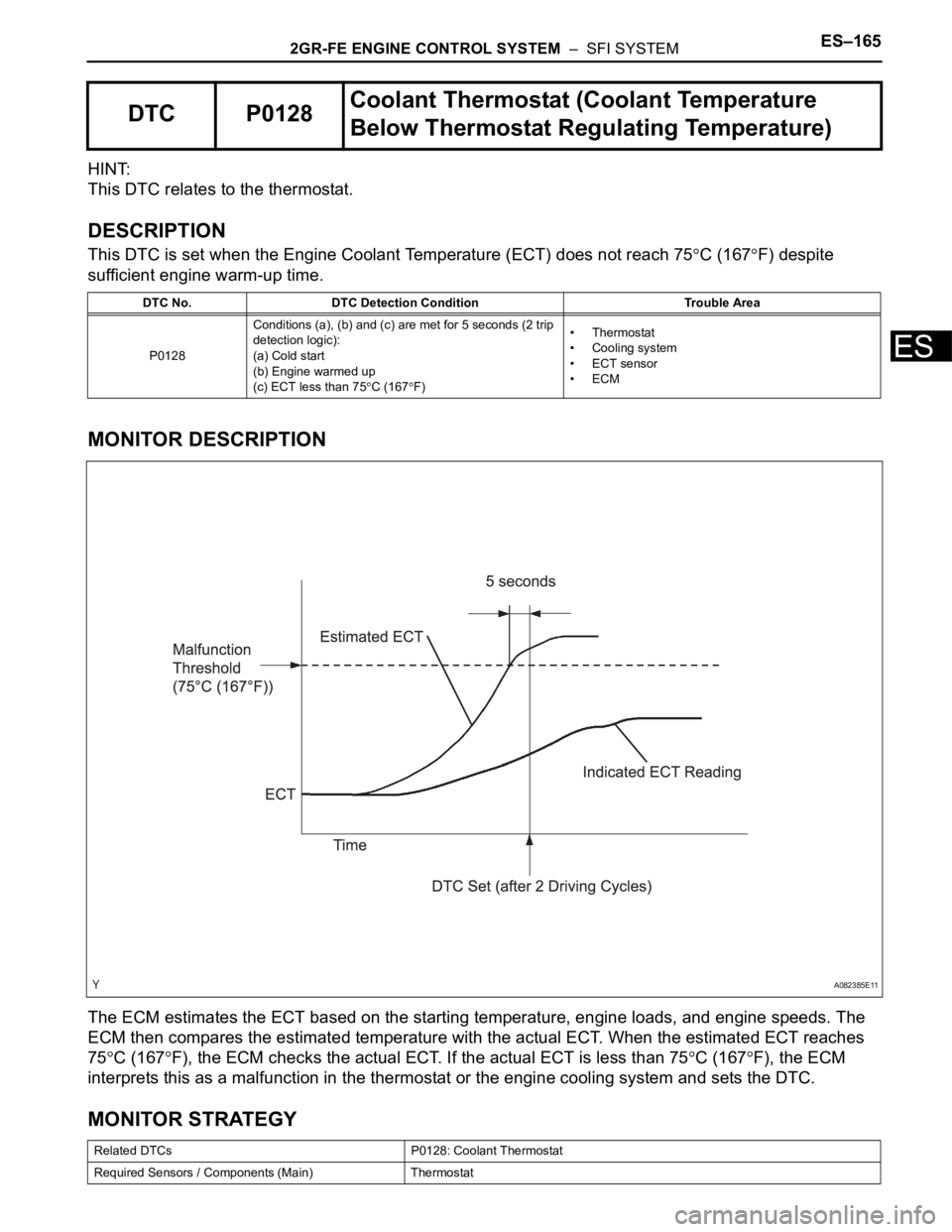
The ECM estimates the ECT based on the starting temperature, engine loads, and engine speeds. The
ECM then compares the estimated temperature with the actual ECT. When the estimated ECT reaches
75
C (167F), the ECM checks the actual ECT. If the actual ECT is less than 75C (167F), the ECM
interprets this as a malfunction in the thermostat or the engine cooling system and sets the DTC.
MONITOR STRATEGY
DTC P0128Coolant Thermostat (Coolant Temperature
Below Thermostat Regulating Temperature)
DTC No. DTC Detection Condition Trouble Area
P0128Conditions (a), (b) and (c) are met for 5 seconds (2 trip
detection logic):
(a) Cold start
(b) Engine warmed up
(c) ECT less than 75
C (167F)•Thermostat
• Cooling system
• ECT sensor
•ECM
Related DTCs P0128: Coolant Thermostat
Required Sensors / Components (Main) Thermostat
A082385E11
Page 473 of 3000
2GR-FE ENGINE CONTROL SYSTEM – SFI SYSTEMES–167
ES
Result
HINT:
If any DTCs other than P0128 are output, troubleshoot
those DTCs first.
B
A
(a) Check for defects in the cooling system that might cause
the system to be too cold, such as abnormal radiator fan
operation or any modifications.
NG
OK
(a) Remove the thermostat (See page CO-16).
(b) Check the valve opening temperature of the thermostat
(See page CO-17).
Standard:
80 to 84
C (176 to 183F)
HINT:
In addition to the above check, confirm that the valve is
completely closed when the temperature is below the
standard.
(c) Reinstall the thermostat (See page CO-17).
NG
OK
Display (DTC Output) Proceed to
P0128 A
P0128 and other DTCs B
GO TO DTC CHART (See page ES-56)
2CHECK COOLING SYSTEM
REPAIR OR REPLACE COOLING SYSTEM
3INSPECT THERMOSTAT
REPLACE THERMOSTAT (See page CO-16)
REPLACE ECM (See page ES-498)
Page 700 of 3000

ES–4142GR-FE ENGINE CONTROL SYSTEM – SFI SYSTEM
ES
(2) Turn the ignition switch off and wait for 6 hours (8 or 10.5 hours).
HINT:
Do not start the engine until checking MONITOR STATUS. If the engine is started, the steps
described above must be repeated.
(c) Monitor Status
(1) Connect the intelligent tester to the DLC3.
(2) Turn the ignition switch to the ON position and turn the tester on.
(3) Select the following menu items: DIAGNOSIS / ENHANCED OBD II / MONITOR STATUS.
(4) Check the "Monitor Status" displayed on the tester.
HINT:
If INCMP is displayed, the monitor is not completed. Make sure that the preconditions have
been met, and perform "Monitor Conditions" again.
2. PURGE FLOW MONITOR CONFIRMATION (P0441)
HINT:
Perform this monitor confirmation after the Key-Off Monitor Confirmation shows COMPL (complete).
(a) Preconditions
The monitor will not run unless:
• The vehicle has been driven for 10 minutes or more (in a city area or on a freeway)
• The ECT is between 4.4
C and 35C (40F and 95F)
• The IAT is between 4.4
C and 35C (40F and 95F)
(b) Monitor Conditions
(1) Release the pressure from the fuel tank by removing and reinstalling the fuel tank cap.
(2) Warm the engine up until the ECT reaches more than 75
C (167F).
(3) Increase the engine speed to 3000 rpm once.
(4) Allow the engine to idle and turn the A/C ON for 1 minute.
(c) Monitor Status
(1) Turn the ignition switch off.
(2) Connect the intelligent tester to the DLC3.
(3) Turn the ignition switch to the ON position and turn the tester on.
(4) Select the following menu items: DIAGNOSIS / ENHANCED OBD II / MONITOR STATUS.
(5) Check the "Monitor Status" displayed on the tester.
HINT:
If INCMP is displayed, the monitor is not completed. Make sure that the preconditions have
been met, and perform "Monitor Conditions" again.
MONITOR RESULT
Refer to Checking Monitor Status for detailed information (See page ES-19).
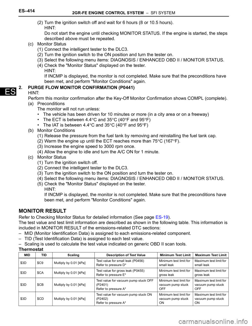
The test value and test limit information are described as shown in the following table. This information is
included in MONITOR RESULT of the emissions-related DTC sections:
– MID (Monitor Identification Data) is assigned to each emissions-related component.
– TID (Test Identification Data) is assigned to each test value.
– Scaling is used to calculate the test value indicated on generic OBD II scan tools.
Thermostat
MID TID Scaling Description of Test Value Minimum Test Limit Maximum Test Limit
$3D $C9 Multiply by 0.01 [kPa]Test value for small leak (P0456)
Refer to pressure D*Minimum test limit for
small leakMaximum test limit for
small leak
$3D $CA Multiply by 0.01 [kPa]Test value for gross leak (P0455)
Refer to pressure E*Minimum test limit for
gross leakMaximum test limit for
gross leak
$3D $CB Multiply by 0.01 [kPa]Test value for vacuum pump stuck OFF
(P2401)
Refer to pressure A*Minimum test limit for
vacuum pump stuck
OFFMaximum test limit for
vacuum pump stuck
OFF
$3D $CD Multiply by 0.01 [kPa]Test value for vacuum pump stuck ON
(P2402)
Refer to pressure A*Minimum test limit for
vacuum pump stuck
ONMaximum test limit for
vacuum pump stuck
ON
Page 794 of 3000

ES–222GR-FE ENGINE CONTROL SYSTEM – SFI SYSTEM
ES
CHECKING MONITOR STATUS
The purpose of the monitor result (mode 06) is to allow
access to the results for on-board diagnostic monitoring tests
of specific components/systems that are not continuously
monitored. Examples are catalyst, evaporative emission
(EVAP) and thermostat.
The monitor result allows the OBD II scan tool to display the
monitor status, test value, minimum test limit and maximum
test limit. These data are displayed after the vehicle has been
driven to run the monitor.
When the test value is not between the minimum test limit
and maximum test limit, the ECM (PCM) interprets this as a
malfunction. When the component is not malfunctioning, if the
difference of the test value and test limit is very small, the
component will malfunction in the near future.
Perform the following instructions to view the monitor status.
Although the Lexus diagnostic tester is used in the following
instructions, it can be checked using a generic OBD II scan
tool. Refer to your scan tool operator's manual for specific
procedures.
1. PERFORM MONITOR DRIVE PATTERN
The monitor results and test values can be checked with
the OBD II scan tool or the intelligent tester. The engine
control module (ECM) monitors the emissions-related
components such as the thermostat, catalyst converter
and evaporative emissions (EVAP), and determines
whether they are functioning normally or not. When
monitoring is finished, the ECM stores the monitor
results and the test values. The monitor result indicates
whether the component is functioning normally or not.
The test value is the value that was used to determine
the monitor result. If the test value is outside of the test
limit (malfunction criterion), the ECM determines the
component is malfunctioning. Some emissions-related
components have multiple test values to determine
monitor result. If one of these test values is outside of the
test limit, the ECM determines the component is
malfunctioning.
(a) Connect the intelligent tester to the DLC3.
(b) Start the engine and turn the tester on.
(c) Clear the DTCs.
(d) Run the vehicle in accordance with the applicable
drive pattern described in READINESS MONITOR
DRIVE PATTERN (See page ES-22). DO NOT turn
the ignition switch off.
NOTICE:
The test results will be lost if the ignition switch
is turned off.
Page 886 of 3000
2GR-FE ENGINE MECHANICAL – ENGINE UNITEM–81
EM
16. REMOVE WATER INLET HOUSING
(a) Remove the 2 nuts, water inlet and thermostat.
(b) Remove the gasket.
(c) Remove the drain cock plug.
(d) Remove the drain cock assembly.
(e) Remove the 2 stud bolts.
(f) Separate the No. 1 water by-pass hose.
(g) Remove the 2 bolts, nut, and water inlet housing.
(h) Remove the 2 O-rings.
17. REMOVE WATER OUTLET
(a) Remove the 2 bolts, 4 nuts and water outlet.
(b) Remove the 2 gaskets and O-ring.
A129673
A134879E01
A129675
A129676E01
A129677
Page 967 of 3000
EM–1582GR-FE ENGINE MECHANICAL – ENGINE UNIT
EM
(b) Install the stud bolts.
Torque: 4.0 N*m (41 kgf*cm, 35 in.*lbf)
(c) Install the water inlet housing with the 2 bolts and
nut.
Torque: 10 N*m (102 kgf*cm, 7 ft.*lbf)
NOTICE:
Be careful that the O-ring does not get caught
between the parts.
(d) Connect the No. 1 water by-pass hose.
(e) Apply adhesive around the drain cock.
Adhesive:
Toyota Genuine Adhesive 1324, Three Bond
1324 or equivalent
(f) Install the drain cock assembly to the water inlet
housing.
Torque: 30 N*m (306 kgf*cm, 22 ft.*lbf)
(g) Install the drain cock plug to the water drain cock
assembly.
Torque: 13 N*m (130 kgf*cm, 9 ft.*lbf)
(h) Install a new gasket to the thermostat.
(i) Align the thermostat jiggle valve with the upper stud
bolt, and insert the thermostat in the water inlet
housing.
HINT:
The jiggle valve may be set within 10
of either side
of the prescribed positions.
A137975E01
A134879E01
A134896E01
Page 1028 of 3000
2GR-FE ENGINE MECHANICAL – ENGINE UNITEM–81
EM
16. REMOVE WATER INLET HOUSING
(a) Remove the 2 nuts, water inlet and thermostat.
(b) Remove the gasket.
(c) Remove the drain cock plug.
(d) Remove the drain cock assembly.
(e) Remove the 2 stud bolts.
(f) Separate the No. 1 water by-pass hose.
(g) Remove the 2 bolts, nut, and water inlet housing.
(h) Remove the 2 O-rings.
17. REMOVE WATER OUTLET
(a) Remove the 2 bolts, 4 nuts and water outlet.
(b) Remove the 2 gaskets and O-ring.
A129673
A134879E01
A129675
A129676E01
A129677
Page 1105 of 3000
EM–1582GR-FE ENGINE MECHANICAL – ENGINE UNIT
EM
(b) Install the stud bolts.
Torque: 4.0 N*m (41 kgf*cm, 35 in.*lbf)
(c) Install the water inlet housing with the 2 bolts and
nut.
Torque: 10 N*m (102 kgf*cm, 7 ft.*lbf)
NOTICE:
Be careful that the O-ring does not get caught
between the parts.
(d) Connect the No. 1 water by-pass hose.
(e) Apply adhesive around the drain cock.
Adhesive:
Toyota Genuine Adhesive 1324, Three Bond
1324 or equivalent
(f) Install the drain cock assembly to the water inlet
housing.
Torque: 30 N*m (306 kgf*cm, 22 ft.*lbf)
(g) Install the drain cock plug to the water drain cock
assembly.
Torque: 13 N*m (130 kgf*cm, 9 ft.*lbf)
(h) Install a new gasket to the thermostat.
(i) Align the thermostat jiggle valve with the upper stud
bolt, and insert the thermostat in the water inlet
housing.
HINT:
The jiggle valve may be set within 10
of either side
of the prescribed positions.
A137975E01
A134879E01
A134896E01