Page 222 of 436
’07 HIGHLANDER HV_U (L/O 0608)
210
2007 HIGHLANDER HV from July ’06 Prod. (OM48685U)
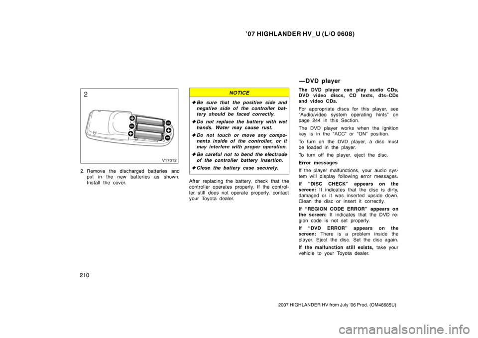
2. Remove the discharged batteries andput in the new batteries as shown.
Install the cover.
NOTICE
�Be sure that the positive side and
negative side of the controller bat-
tery should be faced correctly.
� Do not replace the battery with wet
hands. Water may cause rust.
� Do not touch or move any compo-
nents inside of the controller, or it
may interfere with proper operation.
� Be careful not to bend the electrode
of the controller battery insertion.
� Close the battery case securely.
After replacing the battery, check that the
controller operates properly. If the control-
ler still does not operate properly, contact
your Toyota dealer. The DVD player can play audio CDs,
DVD video discs, CD texts, dts�CDs
and video CDs.
For appropriate discs for this player, see
“Audio/video system operating hints” on
page 244 in this Section.
The DVD player works when the ignition
key is in the “ACC” or “ON” position.
To turn on the DVD player, a disc must
be loaded in the player.
To turn off the player, eject the disc.
Error messages
If the player malfunctions, your audio sys-
tem will display following error messages.
If “DISC CHECK” appears on the
screen:
It indicates that the disc is dirty,
damaged or it was inserted upside down.
Clean the disc or insert it correctly.
If “REGION CODE ERROR” appears on
the screen: It indicates that the DVD re-
gion code is not set properly.
If “DVD ERROR” appears on the
screen: There is a problem inside the
player. Eject the disc. Set the disc again.
If the malfunction still exists, take your
vehicle to your Toyota dealer.
—DVD player
Page 286 of 436

’07 HIGHLANDER HV_U (L/O 0608)
274
2007 HIGHLANDER HV from July ’06 Prod. (OM48685U)
Energy Monitor screen
Touching the “Energy” switch turns on
the “Energy Monitor” that displays the
hybrid system operating condition.
The arrow on the screen indicates the
movement of the energy. See “Energy
monitor” on page 2 for the representative
screen.
The segment of the battery on the screen
indicates the status of the hybrid battery.
See “—Hybrid battery status” on page 4
for details.
To reset the hour: Push the “H” button.
To reset the minutes: Push the “M” button.
The key must be in the “ACC” or “ON”
position.
If the electrical power source has been
disconnected from the clock, the time dis-
play will automatically be set to 1:00 (one
o’clock).The direction is indicated on the inside
rear view mirror.
If the ignition switch was turned off with
the system on, the system will automati-
cally turn back on when the ignition switch
is turned on.
Push the “
” switch to turn the compass
system on and off.
Clock Compass
Page 287 of 436
’07 HIGHLANDER HV_U (L/O 0608)
275
2007 HIGHLANDER HV from July ’06 Prod. (OM48685U)
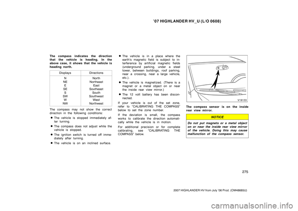
The compass indicates the direction
that the vehicle is heading. In the
above case, it shows that the vehicle is
heading north.Displays
Directions
N
NE E
SE
S
SW W
NWNorth
Northeast East
Southeast
South
Southwest West
Northwest
The compass may not show the correct
direction in the following conditions:
�The vehicle is stopped immediately af-
ter turning.
�The compass does not adjust while the
vehicle is stopped.
�The ignition switch is turned off imme-
diately after turning.
�The vehicle is on an inclined surface.
�The vehicle is in a place where the
earth’s magnetic field is subject to in-
terference by artificial magnetic fields
(underground parking, under a steel
tower, between buildings, roof parking,
near a crossing, near a large vehicle,
etc.).
�The vehicle is magnetized. (There is a
magnet or a metal object on or near
the inside rear view mirror.)
�The 12 volt battery has been discon-
nected.
If your vehicle is out of the set zone,
refer to “CALIBRATING THE COMPASS”
below to set the zone number.
If the deviation is small, the compass
works to calibrate the direction automati-
cally while the vehicle is in motion.
For additional precision or for complete
calibrating, see “CALIBRATING THE
COMPASS” below.
The compass sensor is on the inside
rear view mirror.
NOTICE
Do not put magnets or a metal object
on or near the inside rear view mirror
of the vehicle. Doing this may cause
malfunction of the compass sensor.
Page 290 of 436
’07 HIGHLANDER HV_U (L/O 0608)
278
2007 HIGHLANDER HV from July ’06 Prod. (OM48685U)
CALIBRATING THE COMPASS (circling
calibration)
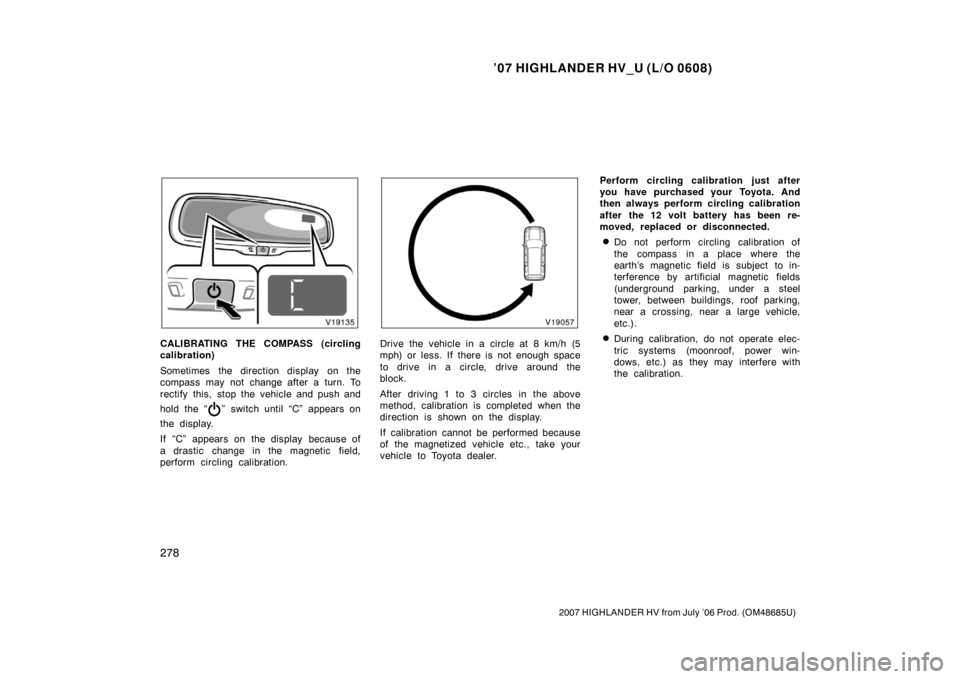
Sometimes the direction display on the
compass may not change after a turn. To
rectify this, stop the vehicle and push and
hold the “
” switch until “C” appears on
the display.
If “C” appears on the display because of
a drastic change in the magnetic field,
perform circling calibration.
Drive the vehicle in a circle at 8 km/h (5
mph) or less. If there is not enough space
to drive in a circle, drive around the
block.
After driving 1 to 3 circles in the above
method, calibration is completed when the
direction is shown on the display.
If calibration cannot be performed because
of the magnetized vehicle etc., take your
vehicle to Toyota dealer. Perform circling calibration just after
you have purchased your Toyota. And
then always perform circling calibration
after the 12 volt battery has been re-
moved, replaced or disconnected.
�Do not perform circling calibration of
the compass in a place where the
earth’s magnetic field is subject to in-
terference by artificial magnetic fields
(underground parking, under a steel
tower, between buildings, roof parking,
near a crossing, near a large vehicle,
etc.).
�During calibration, do not operate elec-
tric systems (moonroof, power win-
dows, etc.) as they may interfere with
the calibration.
Page 292 of 436
’07 HIGHLANDER HV_U (L/O 0608)
280
2007 HIGHLANDER HV from July ’06 Prod. (OM48685U)
Type A (center cluster)
Type B (container)
Type C (luggage compartment)
The power outlets (12 VDC) are de-
signed for power supply for car acces-
sories.
The key must be in the “ACC” or “ON”
position for the power outlets to be used.
NOTICE
�To prevent the fuse from being
blown, do not use the electricity
over the total vehicle capacity of
12VDC/120W (front and rear outlets
together).
� To prevent the 12 volt battery from
being discharged, do not use the
power outlets longer than necessary
when the hybrid system is off.
� Close the power outlet lids when
the power outlets are not in use.
Inserting a foreign object other than
the appropriate plug that fits the
outlet, or allowing any liquid into
the outlet may cause electrical fail-
ure or short circuits.
Power outlets (12 VDC)
Page 293 of 436
’07 HIGHLANDER HV_U (L/O 0608)
281
2007 HIGHLANDER HV from July ’06 Prod. (OM48685U)
This power outlet (115 VAC) is designed
for use as a power supply for electric
appliances in the vehicle.
The key must be in the “ON” position for
the power outlet to be used.
The maximum capacity for this power out-
let is 115 VAC/100W. If you attempt to
use an appliance that requires more than
115 VAC or 100W, the protection circuit
will activate and cut the power supply.
The power supply will restart automatically
when you use an appliance that operates
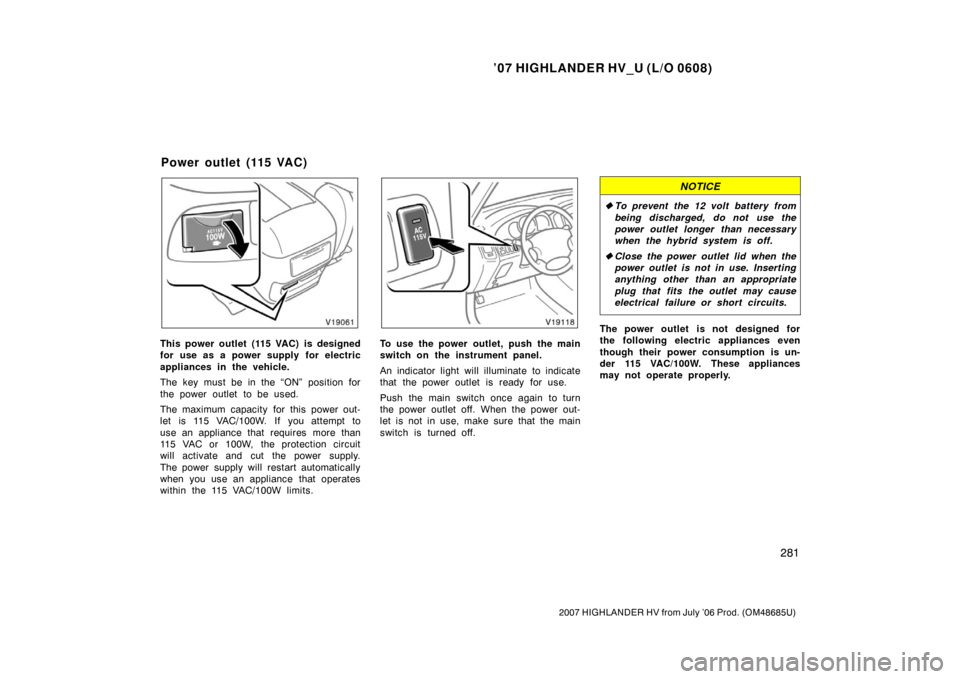
within the 115 VAC/100W limits.To use the power outlet, push the main
switch on the instrument panel.
An indicator light will illuminate to indicate
that the power outlet is ready for use.
Push the main switch once again to turn
the power outlet off. When the power out-
let is not in use, make sure that the main
switch is turned off.
NOTICE
�To prevent the 12 volt battery from
being discharged, do not use the
power outlet longer than necessary
when the hybrid system is off.
� Close the power outlet lid when the
power outlet is not in use. Inserting
anything other than an appropriate
plug that fits the outlet may cause
electrical failure or short circuits.
The power outlet is not designed for
the following electric appliances even
though their power consumption is un-
der 115 VAC/100W. These appliances
may not operate properly.
Power outlet (115 VAC)
Page 295 of 436
’07 HIGHLANDER HV_U (L/O 0608)
283
2007 HIGHLANDER HV from July ’06 Prod. (OM48685U)
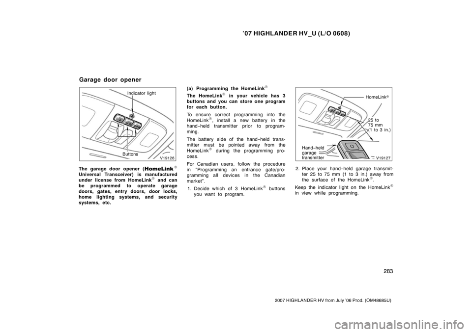
Indicator light
Buttons
The garage door opener (\b
Universal Transceiver) is manufactured
under license from HomeLink\b and can
be programmed to operate garage
doors, gates, entry doors, door locks,
home lighting systems, and security
systems, etc. (a) Programming the HomeLink
\b
The HomeLink\b in your vehicle has 3
buttons and you can store one program
for each button.
To ensure correct programming into the
HomeLink
\b, install a new battery in the
hand− held transmitter prior to program-
ming.
The battery side of the hand −held trans-
mitter must be pointed away from the
HomeLink
\b during the programming pro-
cess.
For Canadian users, follow the procedure
in “Programming an entrance gate/pro-
gramming all devices in the Canadian
market”.
1. Decide which of 3 HomeLink
\b buttons
you want to program.
HomeLink �
Hand −held
garage
transmitter
25 to
75 mm
(1 to 3 in.)
2. Place your hand −held garage transmit-
ter 25 to 75 mm (1 to 3 in.) away from
the surface of the HomeLink
\b.
Keep the indicator light on the HomeLink
\b
in view while programming.
Garage door opener
Page 327 of 436

’07 HIGHLANDER HV_U (L/O 0608)
315
2007 HIGHLANDER HV from July ’06 Prod. (OM48685U)
Ti r e relat ed ter mMeaning
Normal occupant weight68 kg (150 lb.) times the number of occupants specified in the second
column of Table 1 that follows
Occupant distributiondistribution of occupants in a vehicle as specified in the third column of Table
1 that follows
Production options weight
the combined weight of those installed regular production options weighing
over 2.3 kg (5 lb.) in excess of those standard items which they replace,
not previously considered in curb weight or accessory weight, including
heavy duty brakes, ride levelers, roof rack, heavy duty battery, and special
trim
Recommended inflation pressurecold tire inflation pressure recommended by a manufacturer
Rima metal support for a tire or a tire and tube assembly upon which the tire beads
are seated
Rim diameter (Wheel diameter)nominal diameter of the bead seat
Rim size designationrim diameter and width
Rim type designationthe industry of manufacturer ’s designation for a rim by style or code
Rim widt hnominal distance between rim flanges
Vehicle capacity weight
(Total load capacity)the rated cargo and luggage load plus 68 kg (150 lb.) times the vehicle’s desig-
nated seating capacity
Vehicle maximum load on the tirethe load on an individual tire that is determined by distributing to each axle
its share of the maximum loaded vehicle weight and dividing by two