2007 SUZUKI XL7 spare wheel
[x] Cancel search: spare wheelPage 226 of 274

5-42 SERVICE AND APPEARANCE CARE
78J00-03E
811105
9) Remove any rust or dirt from the wheel
bolts, mounting surfaces, and spare
wheel.
10)Place the compact spare tire on the
wheel-mounting surface.
11)Reinstall the wheel nuts. Tighten each
nut by hand until the wheel is held
against the hub.
1152288
12)Lower the vehicle by turning the jack
handle counterclockwise.
808642
13)Tighten the wheel nuts firmly in a criss-
cross sequence, as shown.
14)Lower the jack all the way and remove
the jack from under the vehicle.
15)Tighten the wheel nuts firmly with the
wheel wrench.
WARNING
Never use oil or grease on studs or
nuts. If you do, the nuts might come
loose. Your wheel could fall off, caus-
ing a serious accident.
WARNING
Incorrect wheel nuts or improperly
tightened wheel nuts can cause the
wheel to come loose and even come
off. This could lead to an accident. Be
sure to use the correct wheel nuts. If
you have to replace them, be sure to
get new SUZUKI original equipment
wheel nuts. Stop somewhere as soon
as you can and have the nuts tight-
ened with a torque wrench to the
proper torque specification. Refer to
“Capacities and Specifications” in
this section for wheel nut torque
specification.
CAUTION
Improperly tightened wheel nuts can
lead to brake pulsation and rotor
damage. To avoid expensive brake
repairs, evenly tighten the wheel nuts
in the proper sequence and to the
proper torque specification. Refer to
“Capacities and Specifications” in
this section for the wheel nut torque
specification.
Page 227 of 274

5-43 SERVICE AND APPEARANCE CARE
78J00-03E
Secondary Latch System
Your vehicle has an underbody mounted
tire hoist assembly equipped with a sec-
ondary latch system. It is designed to stop
the compact spare tire from suddenly fall-
ing off your vehicle if the cable holding the
spare tire is damaged. For the secondary
latch to work, the tire must be stowed with
the valve stem pointing down. Refer to
“Storing a Flat or Spare Tire and Tools” in
this section for instructions on storing the
spare tire correctly.To release the spare tire from the second-
ary latch, do the following:
1) If the cable is not visible, start this pro-
cedure at Step 3.
806961
2) If the cable is visible, place the wrench
on the hoist drive nut and turn the
wrench counterclockwise until approxi-
mately 6 inches (15 cm) of cable is
exposed.
3) Attach the wheel wrench to the jack and
raise the jack at least 10 turns.
4) Place the jack under the vehicle, ahead
of the rear bumper. Position the center
lift point of the jack under the center of
the spare tire.
806546
5) Turn the wheel wrench clockwise to
raise the jack until it lifts the secondary
latch spring.
6) Keep raising the jack until the spare tire
stops moving upward and is held firmly
in place, this lets you know that the sec-
ondary latch has released.
7) Lower the jack by turning the wheel
wrench counterclockwise. Keep lower-
ing the jack until the spare tire is resting
on the wheel wrench.
WARNING
Before beginning this procedure read
all the instructions. Failure to read
and follow the instructions could
damage the hoist assembly and you
and others could get hurt. Read and
follow the instructions listed next.
WARNING
Someone standing too close during
the procedure could be injured by the
jack. If the spare tire does not slide
off the jack completely, make sure no
one is behind you or on either side of
you as you pull the jack out from the
under spare.
Page 228 of 274

5-44 SERVICE AND APPEARANCE CARE
78J00-03E
806548
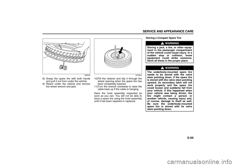
8) Grasp the spare tire with both hands
and pull it out from under the vehicle.
9) Reach under the vehicle and remove
the wheel wrench and jack.
1613524
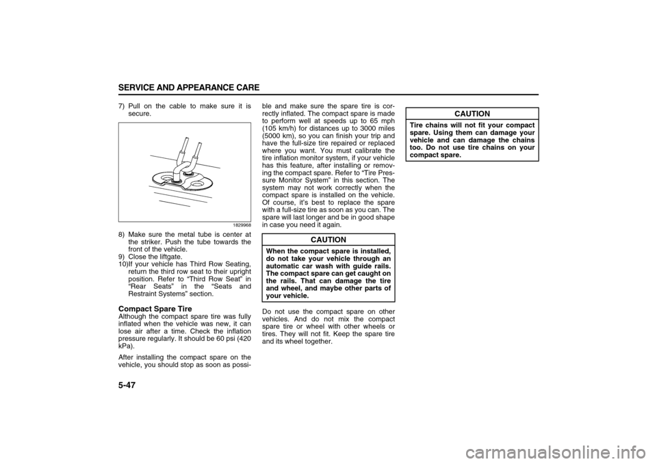
10)Tilt the retainer and slip it through the
wheel opening when the spare tire has
been completely lowered.
11)Turn the wrench clockwise to raise the
cable back up if the cable is hanging.
Have the hoist assembly inspected as
soon as you can. You will not be able to
store a spare tire using the hoist assembly
until it has been repaired or replaced.Storing a Compact Spare Tire
WARNING
Storing a jack, a tire, or other equip-
ment in the passenger compartment
of the vehicle could cause injury. In a
sudden stop or collision, loose
equipment could strike someone.
Store all these in the proper place.
WARNING
The underbody-mounted spare tire
needs to be stored with the valve
stem pointing down. If the spare tire
is stored with the valve stem pointing
upward, its secondary latch will not
work properly and the spare tire
could loosen and suddenly fall from
your vehicle. If this happened when
your vehicle was being driven, the
tire might contact a person or
another vehicle, causing injury and,
of course, damage to itself as well.
Be sure the underbody-mounted
spare tire is stored with its valve
stem pointing down.
Page 229 of 274

5-45 SERVICE AND APPEARANCE CARE
78J00-03E
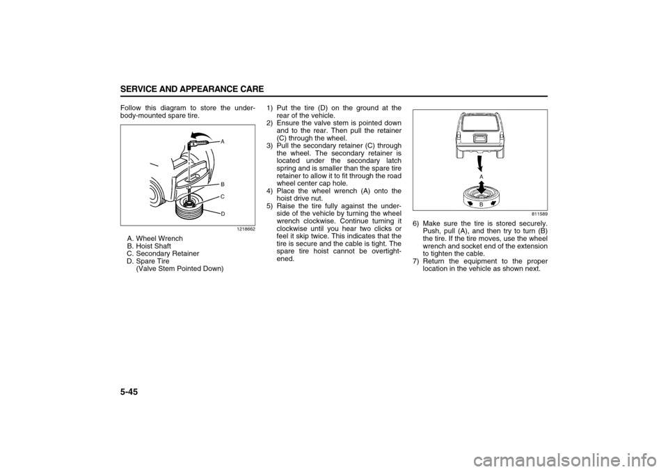
Follow this diagram to store the under-
body-mounted spare tire.
1218662
A. Wheel Wrench
B. Hoist Shaft
C. Secondary Retainer
D. Spare Tire
(Valve Stem Pointed Down)1) Put the tire (D) on the ground at the
rear of the vehicle.
2) Ensure the valve stem is pointed down
and to the rear. Then pull the retainer
(C) through the wheel.
3) Pull the secondary retainer (C) through
the wheel. The secondary retainer is
located under the secondary latch
spring and is smaller than the spare tire
retainer to allow it to fit through the road
wheel center cap hole.
4) Place the wheel wrench (A) onto the
hoist drive nut.
5) Raise the tire fully against the under-
side of the vehicle by turning the wheel
wrench clockwise. Continue turning it
clockwise until you hear two clicks or
feel it skip twice. This indicates that the
tire is secure and the cable is tight. The
spare tire hoist cannot be overtight-
ened.
811589
6) Make sure the tire is stored securely.
Push, pull (A), and then try to turn (B)
the tire. If the tire moves, use the wheel
wrench and socket end of the extension
to tighten the cable.
7) Return the equipment to the proper
location in the vehicle as shown next.
Page 231 of 274

5-47 SERVICE AND APPEARANCE CARE
78J00-03E
7) Pull on the cable to make sure it is
secure.
1829968
8) Make sure the metal tube is center at
the striker. Push the tube towards the
front of the vehicle.
9) Close the liftgate.
10)If your vehicle has Third Row Seating,
return the third row seat to their upright
position. Refer to “Third Row Seat” in
“Rear Seats” in the “Seats and
Restraint Systems” section.Compact Spare TireAlthough the compact spare tire was fully
inflated when the vehicle was new, it can
lose air after a time. Check the inflation
pressure regularly. It should be 60 psi (420
kPa).
After installing the compact spare on the
vehicle, you should stop as soon as possi-ble and make sure the spare tire is cor-
rectly inflated. The compact spare is made
to perform well at speeds up to 65 mph
(105 km/h) for distances up to 3000 miles
(5000 km), so you can finish your trip and
have the full-size tire repaired or replaced
where you want. You must calibrate the
tire inflation monitor system, if your vehicle
has this feature, after installing or remov-
ing the compact spare. Refer to “Tire Pres-
sure Monitor System” in this section. The
system may not work correctly when the
compact spare is installed on the vehicle.
Of course, it’s best to replace the spare
with a full-size tire as soon as you can. The
spare will last longer and be in good shape
in case you need it again.
Do not use the compact spare on other
vehicles. And do not mix the compact
spare tire or wheel with other wheels or
tires. They will not fit. Keep the spare tire
and its wheel together.
CAUTION
When the compact spare is installed,
do not take your vehicle through an
automatic car wash with guide rails.
The compact spare can get caught on
the rails. That can damage the tire
and wheel, and maybe other parts of
your vehicle.
CAUTION
Tire chains will not fit your compact
spare. Using them can damage your
vehicle and can damage the chains
too. Do not use tire chains on your
compact spare.
Page 238 of 274

5-54 SERVICE AND APPEARANCE CARE
78J00-03E
Instrument Panel Fuse Block
The instrument panel fuse block is located
on the passenger’s side of the center con-
sole, to the left of the glove box near the
floor.
1708445
Remove the console cover to access the
fuse block.
1808062
Fuses Usage
1 Sunroof
2 Rear Seat Entertainment
3 Rear Wiper
4 Liftgate
5 Airbags
6 Heated Seats
7 Driver’s Side Turn Signal
8 Door Locks
9Automatic Occupant
Sensing Module
10 Power Mirrors
Fuses Usage
11Passenger’s Side Turn
Signal
12 Amplifier
13Steering Wheel Illumina-
tion
SPARE Spare
SPARE Spare
SPARE Spare
SPARE Spare
SPARE Spare
14 Infotainment
15Climate Control System,
Remote Function Actuator
16 Canister Vent
17 Radio
18 Cluster
19 Ignition Switch
20 Body Control Module
21 Not Used
22Center High-Mounted
Stoplamp, Dimmer
23 Interior Lights
Page 240 of 274

5-56 SERVICE AND APPEARANCE CARE
78J00-03E
Fuses Usage
18 Even Coils, Injectors
19 Odd Coils, Injectors
20 Emission Device 2
21 Spare
22Powertrain Control Mod-
ule, Ignition
23 Transmission
24 Mass Airflow Sensor
25 Airbag Display
26 Spare
27 Stoplamp
28Passenger’s Side Low-
Beam
29 Driver’s Side High-Beam
30 Battery Main 3
32 Spare
33Engine Control Module,
Battery
34Transmission Control
Module, Battery
35 Trailer Park Lamp
36 Front Wiper
Fuses Usage
37Driver’s Side Trailer
Stoplamp, Turn Signal
38 Spare
39 Fuel Pump
40Rear Accessory Power
Outlet
41 All-Wheel Drive
42 Regulated Voltage Control
43Passenger’s Side Trailer
Stoplamp, Turn Signal
44 Spare
45 Front, Rear Washer
48 Rear Defogger
49Anti-lock Brake System
Motor
50 Battery Main 2
52 Daytime Running Lamps
53 Fog Lamps
54Climate Control System
Blower
57 Battery Main 1
63 Electric Power Steering
Relays Usage
31 Ignition Main
46Air Conditioning Compres-
sor Clutch
47 Powertrain
51 Spare
55 Crank
56 Fan 1
58Passenger’s Side Trailer
Stoplamp, Turn Signal
59Driver’s Side Trailer
Stoplamp, Turn Signal
60 Fan 3
61 Fan 2
62 Fuel Pump