2007 SUZUKI SWIFT windshield
[x] Cancel search: windshieldPage 43 of 1496
Downloaded from www.Manualslib.com manuals search engine Maintenance and Lubrication: 0B-13
Brake
Foot brake
Check the following:
• that brake pedal has proper travel,
• that brake works properly,
• that it is free from noise,
• that vehicle does not pull to one side when brake is applied.
• and that brake do not drag.
Parking brake
Check that lever has proper travel.
WARNING!
With vehicle parked on a fairly steep slope,
make sure nothing is in the way downhill to
avoid any personal injury or property
damage. Be prepared to apply regular brake
quickly even if vehicle should start to move.
Check to ensure that parking brake is fully effective
when the vehicle is stopped on the safe slope and brake
lever is pulled all the way.
Steering
• Check to ensure that steering wheel is free from instability, or abnormally heavy feeling. • Check that the vehicle does not wander or pull to one
side.
Engine
• Check that engine responds readily at all speeds.
• Check that engine is free from abnormal noise and abnormal vibration.
Body, Wheels and Power Transmitting System
Check that body, wheels and power transmitting system
are free from abnormal noise and abnormal vibration or
any other abnormal condition.
Meters and Gauge
Check that speedometer, odometer, fuel meter,
temperature gauge, etc. are operating accurately.
Lights
Check that all lights operate properly.
Windshield Defroster
Periodically check that ai r comes out from defroster
outlet when operating heater or air conditioning.
Set mode control lever to defroster position and fan
switch lever to “HI” position for this check.
Specifications
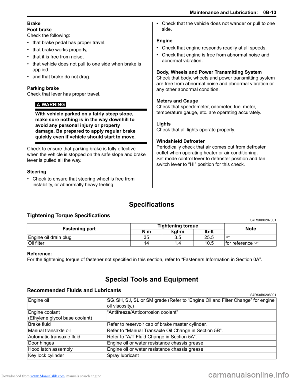
Tightening Torque SpecificationsS7RS0B0207001
Reference:
For the tightening torque of fastener not specified in this section, refer to “Fasteners Information in Section 0A”.
Special Tools and Equipment
Recommended Fluids and LubricantsS7RS0B0208001
Fastening part Tightening torque
Note
N ⋅mkgf-mlb-ft
Engine oil drain plug 35 3.5 25.5 )
Oil filter 14 1.4 10.5 for reference )
Engine oilSG, SH, SJ, SL or SM grade (Refer to “Engine Oil and Filter Change” for engine
oil viscosity.)
Engine coolant
(Ethylene glycol base coolant) “Antifreeze/Antico
rrosion coolant”
Brake fluid Refer to reservoir cap of brake master cylinder.
Manual transaxle oil Refer to “Manual Transaxle Oil Change in Section 5B”.
Automatic transaxle fluid Refer to “A/T Fluid Change in Section 5A”.
Door hinges Engine oil or water resistance chassis grease
Hood latch assembly Engine oil or water resistance chassis grease
Key lock cylinder Spray lubricant
Page 302 of 1496
Downloaded from www.Manualslib.com manuals search engine 1D-17 Engine Mechanical:
Engine Assembly Removal and InstallationS7RS0B1406011
NOTE
After replacing electric throttle body
assembly, perform calibration of throttle
valve referring to “Electric Throttle Body
System Calibration in Section 1C”.
Removal1) Relieve fuel pressure according to “Fuel Pressure Relief Procedure in Section 1G”.
2) Disconnect negative and pos itive cable at battery.
3) Remove battery and tray.
4) Remove engine hood after disconnecting windshield washer hose.
5) Remove right and left side engine under covers.
6) Remove A/C compressor belt by referring to “Compressor Drive Belt Remo val and Installation in
Section 7B” or “Compressor Drive Belt Removal and
Installation in Section 7B”.
7) Drain engine oil, transaxle oil and coolant.
8) Remove cowl top plate referring to “Cowl Top Components in Section 9K”.
9) Remove air cleaner assembly referring to “Air Cleaner Components”.
10) With hose connected, detach A/C compressor from its bracket (A/C model) referring to “Compressor
Assembly Removal and Installation in Section 7B” or
“Compressor Assembly Removal and Installation in
Section 7B”.
CAUTION!
Suspend removed A/C compressor at a place
where no damage will be caused during
removal and installation of engine assembly.
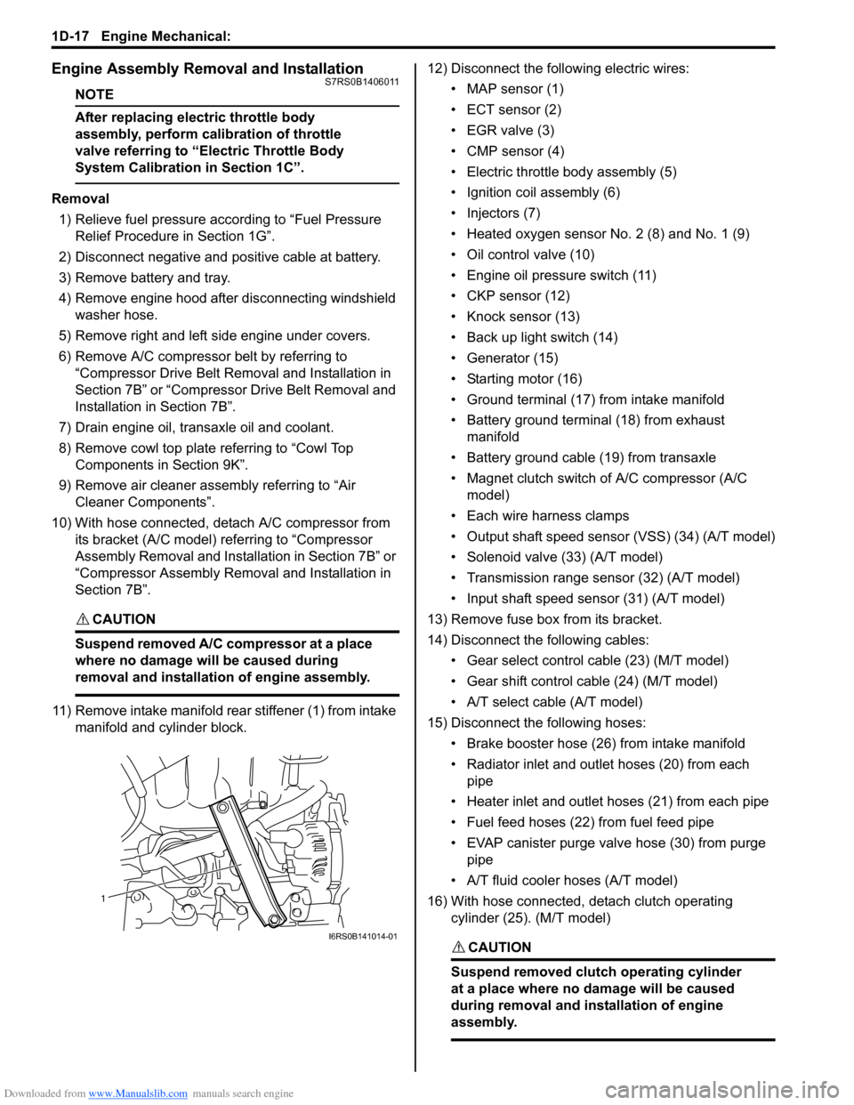
11) Remove intake manifold rear stiffener (1) from intake manifold and cylinder block. 12) Disconnect the following electric wires:
• MAP sensor (1)
• ECT sensor (2)
•EGR valve (3)
• CMP sensor (4)
• Electric throttle body assembly (5)
• Ignition coil assembly (6)
• Injectors (7)
• Heated oxygen sensor No. 2 (8) and No. 1 (9)
• Oil control valve (10)
• Engine oil pressure switch (11)
• CKP sensor (12)
• Knock sensor (13)
• Back up light switch (14)
• Generator (15)
• Starting motor (16)
• Ground terminal (17) from intake manifold
• Battery ground terminal (18) from exhaust manifold
• Battery ground cable (19) from transaxle
• Magnet clutch switch of A/C compressor (A/C model)
• Each wire harness clamps
• Output shaft speed sensor (VSS) (34) (A/T model)
• Solenoid valve (33) (A/T model)
• Transmission range sensor (32) (A/T model)
• Input shaft speed sensor (31) (A/T model)
13) Remove fuse box from its bracket.
14) Disconnect the following cables: • Gear select control cable (23) (M/T model)
• Gear shift control cable (24) (M/T model)
• A/T select cable (A/T model)
15) Disconnect the following hoses: • Brake booster hose (26) from intake manifold
• Radiator inlet and outlet hoses (20) from each pipe
• Heater inlet and outlet hoses (21) from each pipe
• Fuel feed hoses (22) from fuel feed pipe
• EVAP canister purge valve hose (30) from purge pipe
• A/T fluid cooler hoses (A/T model)
16) With hose connected, detach clutch operating cylinder (25). (M/T model)
CAUTION!
Suspend removed clutch operating cylinder
at a place where no damage will be caused
during removal and installation of engine
assembly.
1
I6RS0B141014-01
Page 305 of 1496

Downloaded from www.Manualslib.com manuals search engine Engine Mechanical: 1D-20
15) Install A/C compressor to its bracket (if equipped) referring to “Compressor Assembly Removal and
Installation in Section 7B” or “Compressor Assembly
Removal and Installa tion in Section 7B”.
16) Adjust A/C compressor belt tension (if equipped) referring to “Compressor Drive Belt Inspection and
Adjustment in Section 7B” or “Compressor Drive Belt
Inspection and Adjustment in Section 7B”.
17) Check to ensure that a ll removed parts are back in
place.
Reinstall any necessary parts which have not been
reinstalled.
18) Refill cooling system with coolant referring to “Cooling System Flush and Refill in Section 1F”. 19) Refill engine with engine oil
referring to “Engine Oil
and Filter Change in Section 0B”.
20) Refill transaxle with transa xle oil referring to“Manual
Transaxle Oil Change in Section 5B” or “A/T Fluid
Change in Section 5A”.
21) Install battery and tray.
22) Connect positive and negative cable at battery.
23) Install engine hood and connect windshield washer hose.
24) Verify that there is no fu el leakage, coolant leakage,
oil leakage and exhaust gas leakage at each
connection.
Timing Chain Cover ComponentsS7RS0B1406012
I6RS0C140015-02
1. Crankshaft pulley bolt 13. Oil gallery pipe No.2 bolt
2. Crankshaft pulley 14. Oil gallery pipe No.3
3. Oil seal : Apply engine oil to oil seal lip. 15. Oil gallery pipe No.3 bolt
4. Timing chain cover : Apply sealant 99000-31140 to the mating surface of cylinder and cylinder head.
: Apply sealant 99000-31260 to the mating surface of timing chain cover referring to the
figure of Step 4) of “Installation” under “Timing Chain Cover Removal and Installation”. 16. O-ring
: Apply engine oil.
5. Pin 17. Oil control valve
6. Cap bolt 18. Oil control valve mounting nut
7. Timing chain cover mounting bolts 19. Cap
8. Timing chain cover mounting nut : 11 N ⋅m (1.1 kgf-m, 8.0 lb-ft)
9. Oil gallery pipe No.1 :25 N⋅m (2.5 kgf-m, 18.0 lb-ft)
Page 437 of 1496
Downloaded from www.Manualslib.com manuals search engine Front Suspension: 2B-4
Reference Information
Side slip
When checked with side slip tester, side slip should
satisfy following specification.Side slip
0 to IN 3.0 mm/m (0 to IN 0.118 in/3.3 ft)
If side slip is greatly di
fferent, toe or front wheel
alignment may not be correct.
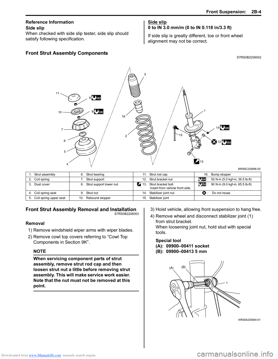
Front Strut Assembly ComponentsS7RS0B2206002
Front Strut Assembly Removal and InstallationS7RS0B2206003
Removal
1) Remove windshield wipe r arms with wiper blades.
2) Remove cowl top covers referring to “Cowl Top
Components in Section 9K”.
NOTE
When servicing component parts of strut
assembly, remove stru t rod cap and then
loosen strut nut a little before removing strut
assembly. This will make service work easier.
Note that the nut must not be removed at this
point.
3) Hoist vehicle, allowing front suspension to hang free.
4) Remove wheel and disconn ect stabilizer joint (1)
from strut bracket.
When loosening joint nu t, hold stud with special
tools.
Special tool
(A): 09900–00411 socket
(B): 09900–00413 5 mm
11 3
2 1
12
13
4
5
6
7
10
8(a)
(b)
9
(a)
14
15(a)
16
I6RS0C220006-02
1. Strut assembly
6. Strut bearing 11. Strut rod cap16. Bump stopper
2. Coil spring 7. Strut support 12. Strut bracket nut : 50 N⋅m (5.0 kgf-m, 36.5 lb-ft)
3. Dust cover 8. Strut support lower nut 13. Strut bracket bolt
:Insert from vehicle front side. : 90 N
⋅m (9.0 kgf-m, 65.5 lb-ft)
4. Coil spring seat 9. Strut nut 14. Stabilizer joint nut : Do not reuse.
5. Coil spring upper seat 10. Rebound stopper 15. Stabilizer joint
1
(A)
(B)
I4RS0A220004-01
Page 438 of 1496
Downloaded from www.Manualslib.com manuals search engine 2B-5 Front Suspension:
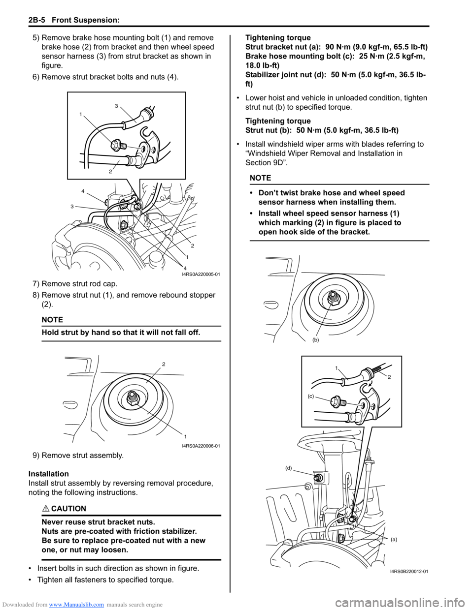
5) Remove brake hose mounting bolt (1) and remove brake hose (2) from bracket and then wheel speed
sensor harness (3) from strut bracket as shown in
figure.
6) Remove strut bracket bolts and nuts (4).
7) Remove strut rod cap.
8) Remove strut nut (1), and remove rebound stopper (2).
NOTE
Hold strut by hand so th at it will not fall off.
9) Remove strut assembly.
Installation
Install strut assembly by reversing removal procedure,
noting the following instructions.
CAUTION!
Never reuse strut bracket nuts.
Nuts are pre-coated with friction stabilizer.
Be sure to replace pre-coated nut with a new
one, or nut may loosen.
• Insert bolts in such direction as shown in figure.
• Tighten all fasteners to specified torque. Tightening torque
Strut bracket nut (a): 90 N·m (9.0 kgf-m, 65.5 lb-ft)
Brake hose mounting bolt (c): 25 N·m (2.5 kgf-m,
18.0 lb-ft)
Stabilizer joint nut (d): 50 N·m (5.0 kgf-m, 36.5 lb-
ft)
• Lower hoist and vehicle in unloaded condition, tighten strut nut (b) to specified torque.
Tightening torque
Strut nut (b): 50 N·m (5.0 kgf-m, 36.5 lb-ft)
• Install windshield wiper arms with blades referring to
“Windshield Wiper Removal and Installation in
Section 9D”.
NOTE
• Don’t twist brake hose and wheel speed sensor harness when installing them.
• Install wheel speed sensor harness (1) which marking (2) in figure is placed to
open hook side of the bracket.
1 3
2
2
1
4
4
3
I4RS0A220005-01
2
1
I4RS0A220006-01
(d) (a)
(b)
(c)
1
2
I4RS0B220012-01
Page 511 of 1496
Downloaded from www.Manualslib.com manuals search engine Brake Control System and Diagnosis: 4A-13
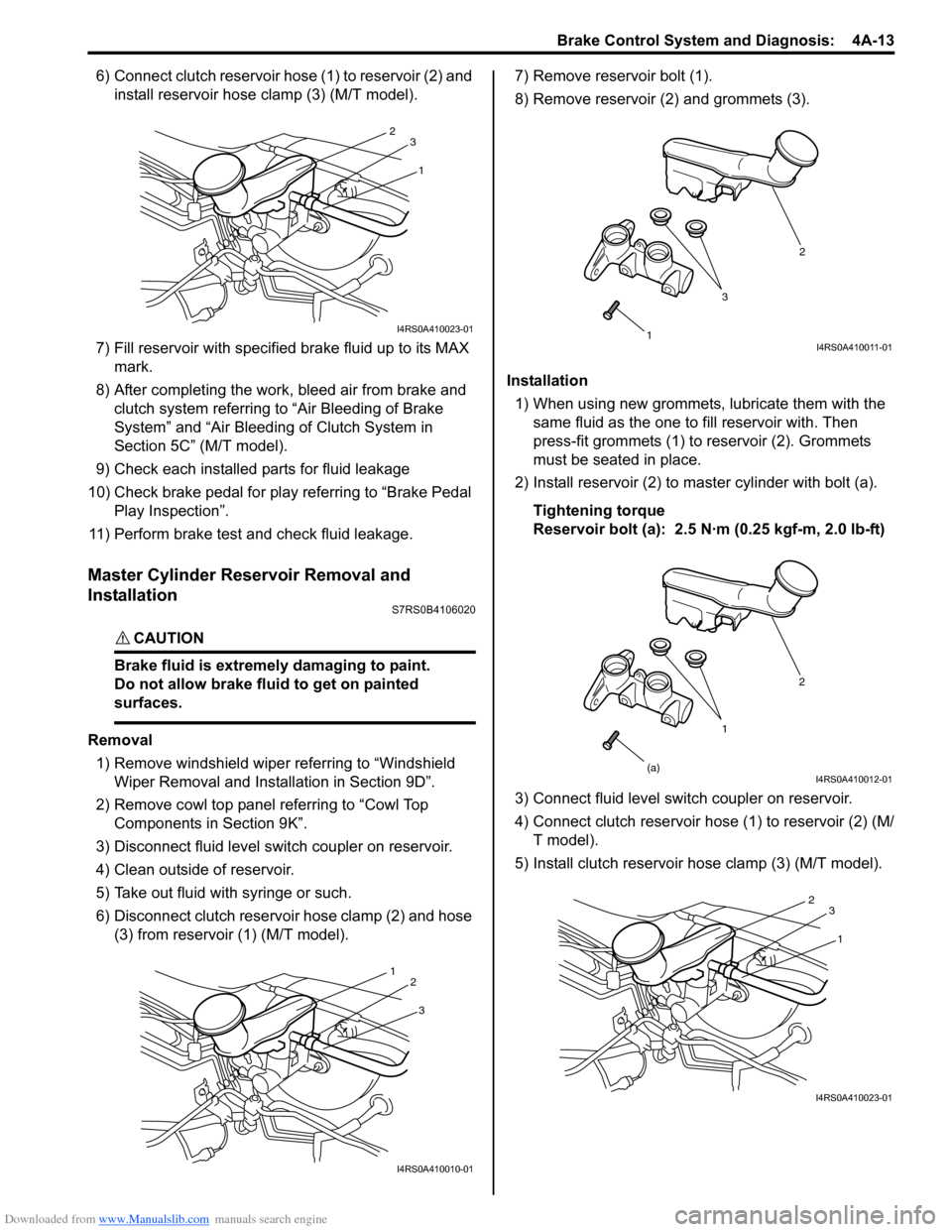
6) Connect clutch reservoir hose (1) to reservoir (2) and install reservoir hose clamp (3) (M/T model).
7) Fill reservoir with specified brake fluid up to its MAX
mark.
8) After completing the work, bleed air from brake and clutch system referring to “Air Bleeding of Brake
System” and “Air Bleeding of Clutch System in
Section 5C” (M/T model).
9) Check each installed parts for fluid leakage
10) Check brake pedal for play referring to “Brake Pedal Play Inspection”.
11) Perform brake test and check fluid leakage.
Master Cylinder Reservoir Removal and
Installation
S7RS0B4106020
CAUTION!
Brake fluid is extremely damaging to paint.
Do not allow brake fluid to get on painted
surfaces.
Removal 1) Remove windshield wiper referring to “Windshield Wiper Removal and Insta llation in Section 9D”.
2) Remove cowl top panel referring to “Cowl Top Components in Section 9K”.
3) Disconnect fluid level s witch coupler on reservoir.
4) Clean outside of reservoir.
5) Take out fluid with syringe or such.
6) Disconnect clutch reservoir hose clamp (2) and hose (3) from reservoir (1) (M/T model). 7) Remove reservoir bolt (1).
8) Remove reservoir (2) and grommets (3).
Installation 1) When using new grommets, lubricate them with the same fluid as the one to fill reservoir with. Then
press-fit grommets (1) to reservoir (2). Grommets
must be seated in place.
2) Install reservoir (2) to master cylinder with bolt (a).
Tightening torque
Reservoir bolt (a): 2.5 N·m (0.25 kgf-m, 2.0 lb-ft)
3) Connect fluid level switch coupler on reservoir.
4) Connect clutch reservoir hose (1) to reservoir (2) (M/ T model).
5) Install clutch reservoir hose clamp (3) (M/T model).
1
2
3
I4RS0A410023-01
3
1
2
I4RS0A410010-01
1 2
3I4RS0A410011-01
1 2
(a)
I4RS0A410012-01
1
2
3
I4RS0A410023-01
Page 512 of 1496
Downloaded from www.Manualslib.com manuals search engine 4A-14 Brake Control System and Diagnosis:
6) Fill reservoir with specified fluid.
7) After completing the work, bleed air from brake and clutch system referring to “Air Bleeding of Brake
System” and “Air Bleeding of Clutch System in
Section 5C” (M/T model).
8) Install cowl top panel referring to “Cowl Top Components in Section 9K”.
9) Install windshield wiper referring to “Windshield
Wiper Removal and Insta llation in Section 9D”.
10) Perform brake test and check each installed part for fluid leakage.
Master Cylinder Assembly Disassembly and
Assembly
S7RS0B4106013
Disassembly
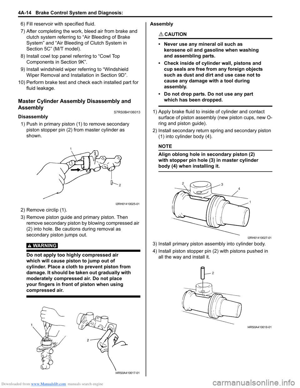
1) Push in primary piston (1) to remove secondary
piston stopper pin (2) from master cylinder as
shown.
2) Remove circlip (1).
3) Remove piston guide and primary piston. Then remove secondary piston by blowing compressed air
(2) into hole. Be cautions during removal as
secondary piston jumps out.
WARNING!
Do not apply too highly compressed air
which will cause piston to jump out of
cylinder. Place a cloth to prevent piston from
damage. It should be taken out gradually with
moderately compressed air. Do not place
your fingers in front of piston when using
compressed air.
Assembly
CAUTION!
• Never use any mineral oil such as kerosene oil and gasoline when washing
and assembling parts.
• Check inside of cylinder wall, pistons and cup seals are free from any foreign objects
such as dust and dirt and use case not to
cause any damage with a tool during
assembly.
• Do not drop parts. Do not use any part which has been dropped.
1) Apply brake fluid to inside of cylinder and contact surface of piston assembly (new piston cups, new O-
ring and piston guide).
2) Install secondary return spring and secondary piston (1) into cylinder body (4).
NOTE
Align oblong hole in secondary piston (2)
with stopper pin hole (3) in master cylinder
body (4) when installing it.
3) Install primary piston assembly into cylinder body.
4) Install piston stopper pin (2) with pistons pushed in all the way and install it.
I2RH01410025-01
I4RS0A410017-01
I2RH01410027-01
I4RS0A410018-01
Page 1161 of 1496
Downloaded from www.Manualslib.com manuals search engine Air Bag System: 8B-123
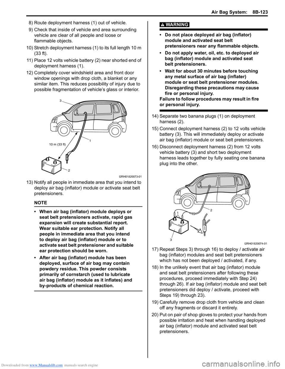
8) Route deployment harness (1) out of vehicle.
9) Check that inside of vehicle and area surrounding vehicle are clear of all people and loose or
flammable objects.
10) Stretch deployment harness (1) to its full length 10 m (33 ft).
11) Place 12 volts vehicle battery (2) near shorted end of deployment harness (1).
12) Completely cover windshield area and front door window openings with drop cloth, a blanket or any
similar item. This reduces possibility of injury due to
possible fragmentation of vehicle’s glass or interior.
13) Notify all people in immediate area that you intend to deploy air bag (inflator) module or activate seat belt
pretensioners.
NOTE
• When air bag (inflator) module deploys or seat belt pretensioners activate, rapid gas
expansion will create substantial report.
Wear suitable ear protection. Notify all
people in immediate area that you intend
to deploy air bag (inflator) module or to
activate seat belt pretensioner and suitable
ear protection should be worn.
• After air bag (inflator) module has been deployed, surface of air bag may contain
powdery residue. This powder consists
primarily of cornstarch (used to lubricate
air bag (inflator) module as it inflates) and
by-products of chemical reaction.
WARNING!
• Do not place deployed air bag (inflator) module and activated seat belt
pretensioners near any flammable objects.
• Do not apply water, oil, etc. to deployed air bag (inflator) module and activated seat
belt pretensioners.
• Wait for about 30 minutes before touching any metal surface of air bag (inflater)
module or seat belt pretensioner modules.
Disregarding these precautions may cause
fire or personal injury.
Failure to follow procedures may result in fire
or personal injury.
14) Separate two banana plugs (1) on deployment harness (2).
15) Connect deployment harness (2) to 12 volts vehicle battery (3). This will immedi ately deploy or activate
air bag (inflator) module or seat belt pretensioners.
16) Disconnect deployment harness (2) from 12 volts vehicle battery (3) and short two deployment
harness leads together by fully seating one banana
plug into the other.
17) Repeat Steps 3) through 16) to deploy / activate air bag (inflator) modules and seat belt pretensioners
which has not been deployed / activated, if any.
18) In the unlikely event that air bag (inflator) module and seat belt pretensioners after following these
procedures, proceed immediately with Step 24)
through 26). If air bag (inflator) module and seat belt
pretensioners did deploy / activate, proceed with
Steps 19) through 23).
19) Carefully remove drop cloth from vehicle and clean off any fragments or discard it entirely.
20) Put on pair of shop gloves to protect your hands from
possible irritation and heat when handling deployed
air bag (inflator) module and activated seat belt
pretensioners.
10 m (33 ft) 1
2
3
I2RH01820073-01
1
3 2
I2RH01820074-01