2007 SUZUKI SWIFT Water hoses
[x] Cancel search: Water hosesPage 11 of 1496
Downloaded from www.Manualslib.com manuals search engine Precautions: 00-6
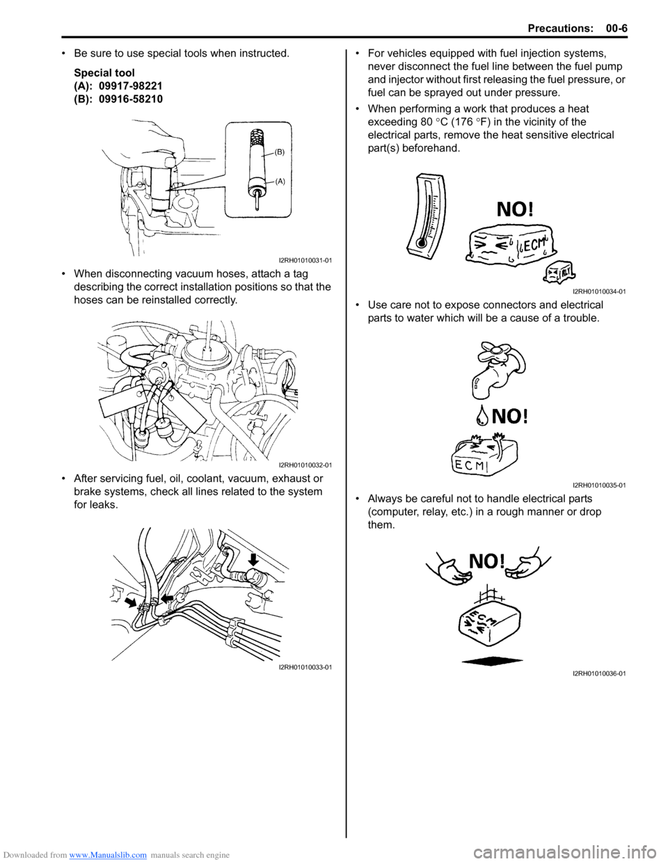
• Be sure to use special tools when instructed.Special tool
(A): 09917-98221
(B): 09916-58210
• When disconnecting vacuum hoses, attach a tag describing the correct installation positions so that the
hoses can be reinstalled correctly.
• After servicing fuel, oil, coolant, vacuum, exhaust or brake systems, check all lin es related to the system
for leaks. • For vehicles equipped with fuel injection systems,
never disconnect the fuel line between the fuel pump
and injector without first releasing the fuel pressure, or
fuel can be sprayed out under pressure.
• When performing a work that produces a heat exceeding 80 °C (176 ° F) in the vicinity of the
electrical parts, remove t he heat sensitive electrical
part(s) beforehand.
• Use care not to expose connectors and electrical parts to water which will be a cause of a trouble.
• Always be careful not to handle electrical parts (computer, relay, etc.) in a rough manner or drop
them.
I2RH01010031-01
I2RH01010032-01
I2RH01010033-01
I2RH01010034-01
I2RH01010035-01
I2RH01010036-01
Page 48 of 1496

Downloaded from www.Manualslib.com manuals search engine 1-iv Table of Contents
Engine Lubrication System.....................1E-1
General Description ............................................. 1E-1
Engine Lubrication Description ........................... 1E-1
Diagnostic Information and Procedures ............ 1E-2 Oil Pressure Check ............................................. 1E-2
Repair Instructions ........... ................................... 1E-3
Heat Exchanger Components ............................. 1E-3
Heat Exchanger On-Vehicle Inspection .............. 1E-4
Heat Exchanger Removal and Installation .......... 1E-4
Oil Pan and Oil Pump Strainer Components....... 1E-5
Oil Pan and Oil Pump Strainer Removal and
Installation ......................................................... 1E-5
Oil Pan and Oil Pump Stra iner Cleaning ............. 1E-7
Oil Pump Components ........................................ 1E-8
Oil Pump Removal and Installation ..................... 1E-8
Oil Pump Disassembly and Reassembly ............ 1E-8
Oil Pump Inspection ............................................ 1E-9
Specifications .... ................................................. 1E-11
Tightening Torque Specifications ...................... 1E-11
Special Tools and Equipmen t ........................... 1E-11
Recommended Service Material ....................... 1E-11
Special Tool ...................................................... 1E-11
Engine Cooling System ..... ...................... 1F-1
General Description .......... ................................... 1F-1
Cooling System Descriptio n ................................ 1F-1
Coolant Description ............................................. 1F-1
Schematic and Routing Diagram ........................ 1F-2 Coolant Circulation .............................................. 1F-2
Diagnostic Information and Procedures ............ 1F-4 Engine Cooling Symptom Diagnosis ................... 1F-4
Repair Instructions ........... ................................... 1F-5
Cooling System Components.............................. 1F-5
Coolant Level Check ........................................... 1F-6
Engine Cooling System Inspection and Cleaning ............................................................ 1F-6
Cooling System Draining.. ................................... 1F-6
Cooling System Flush and Refill ......................... 1F-7
Cooling Water Pipes or Hoses Removal and Installation ......................................................... 1F-7
Thermostat Removal and In stallation.................. 1F-8
Thermostat Inspection......................................... 1F-8
Radiator Cooling Fan Motor On-Vehicle Inspection .......................................................... 1F-9
Radiator Cooling Fan Rela y Inspection............... 1F-9
Radiator Cooling Fan Removal and Installation ....................................................... 1F-10
Radiator On-Vehicle Inspection and Cleaning .. 1F-10
Radiator Removal and Inst allation .................... 1F-10
Water Pump Removal and In stallation .............. 1F-11
Water Pump Inspection ..................................... 1F-11
Specifications .... ................................................. 1F-12
Tightening Torque Specifications ...................... 1F-12
Special Tools and Equipmen t ........................... 1F-12
Recommended Service Material ....................... 1F-12
Fuel System ................... .......................... 1G-1
Precautions.......................................................... 1G-1 Precautions on Fuel System Service ................. 1G-1
General Description ............................................ 1G-1 Fuel System Description .................................... 1G-1
Fuel Delivery System Description ...................... 1G-1
Fuel Pump Description ....................................... 1G-2
Schematic and Routing Diagram ....................... 1G-2 Fuel Delivery System Diag ram........................... 1G-2
Diagnostic Information and Procedures ........... 1G-2 Fuel Pressure Inspection ................................... 1G-2
Fuel Cut Operation Inspection ........................... 1G-3
Repair Instructions ............ ................................. 1G-4
Fuel System Components .................................. 1G-4
Fuel Hose Disconnecting and Reconnecting ..... 1G-5
Fuel Pressure Relief Procedure ......................... 1G-7
Fuel Leakage Check Procedure......................... 1G-7
Fuel Lines On-Vehicle Inspection ...................... 1G-7
Fuel Pipe Removal and Installation.................... 1G-7
Fuel Injector On-Vehicle Inspection ................... 1G-8
Fuel Injector Removal and Installation ............... 1G-8
Fuel Injector Inspection ...................................... 1G-9
Fuel Filler Cap Inspection . ............................... 1G-10
Fuel Tank Inlet Valve Removal and Installation ...................................................... 1G-11
Fuel Tank Inlet Valve Inspection ...................... 1G-12
Fuel Tank Removal and Installation ................. 1G-12
Fuel Tank Inspection ........................................ 1G-13
Fuel Tank Purging Procedure .......................... 1G-14
Fuel Pump On-Vehicle Inspection.................... 1G-14
Fuel Pump Assembly Removal and Installation ...................................................... 1G-14
Main Fuel Level Sensor Removal and Installation ...................................................... 1G-15
Fuel Pump Inspection ...................................... 1G-16
Specifications ..................... ............................... 1G-16
Tightening Torque Specifications ..................... 1G-16
Special Tools and Equipmen t .......................... 1G-17
Special Tool ..................................................... 1G-17
Ignition System .............. .......................... 1H-1
General Description .............................................1H-1
Ignition System Construction ..............................1H-1
Schematic and Routing Diagram ........................1H-2 Ignition System Wiring Circuit Diagram...............1H-2
Component Location ............ ...............................1H-3
Ignition System Components Location................1H-3
Diagnostic Information and Procedures ............1H-4 Ignition System Symptom Diagnosis...................1H-4
Reference Waveform of Ignition System.............1H-4
Ignition System Check ........................................1H-4
Ignition Spark Test ..............................................1H-6
Repair Instructions ............ ..................................1H-6
High-Tension Cord Removal and Installation......1H-6
High-Tension Cord Inspection.............................1H-7
Spark Plug Removal and Installation ..................1H-7
Spark Plug Inspection .........................................1H-7
Ignition Coil Assembly (Including ignitor)
Removal and Installation ...................................1H-8
Ignition Coil Assembly (Including ignitor)
Inspection ..........................................................1H-8
Page 87 of 1496
Downloaded from www.Manualslib.com manuals search engine Engine General Information and Diagnosis: 1A-37
TP SENSOR 2 VOLT (THROTTLE POSITION SENSOR
(SUB) OUTPUT VOLTAGE, V)
The TP sensor (sub) reading provides throttle valve
opening information in the form of voltage.
APP SENSOR 1 VOLT (ACCELERATOR PEDAL
POSITION (APP) SENSOR (MAIN) OUTPUT
VOLTAGE, V)
The APP sensor (main) read ing provides accelerator
pedal opening information in the form of voltage.
APP SENSOR 2 VOLT (ACCELERATOR PEDAL
POSITION (APP) SENSOR (S UB) OUTPUT VOLTAGE,
V)
The APP sensor (sub) reading provides accelerator
pedal opening information in the form of voltage.
ACCEL POSITION (ABSOLUTE ACCELERATOR
PEDAL POSITION, %)
When accelerator pedal is at fully released position,
accelerator pedal is indicated as 0 – 5% and 90 – 100%
fully depressed position. THROTTLE TARGET POSI (TARGET THROTTLE
VALVE POSITION, %)
Target throttle valve position is ECM internal parameter
which indicates the ECM requested throttle valve
position.
BATTERY CURRENT (A)
This parameter indicates elec
tric load value (current
consumption) that detected by electric load current
sensor.
GENERATOR CONT DUTY (GENERATOR CONTROL
DUTY, %)
This parameter indicates generator control duty ratio that
controls production electricity of generator by ECM.
100%: No limitation for the generating
0%: Maximum limitation for the generating
GENERATOR FIELD DUTY (GENERATOR FIELD
COIL DUTY, %)
This parameter indicates ope rating rate (status of
production electricity) for gen erator by field coil duty
ratio.
100%: maximum operation.
0%: minimum operation.
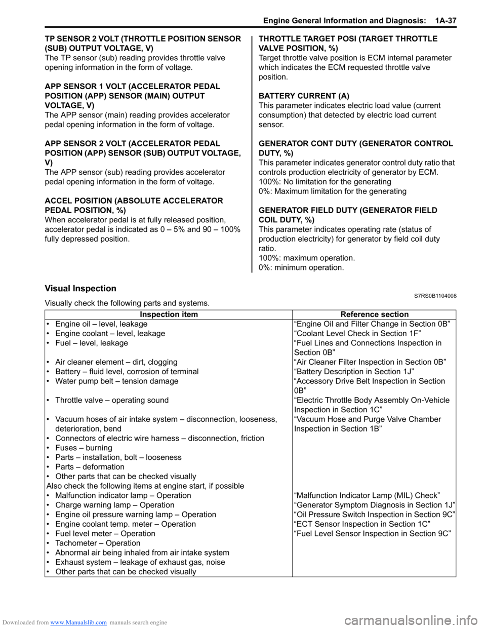
Visual InspectionS7RS0B1104008
Visually check the following parts and systems.
Inspection item Reference section
• Engine oil – level, leakage “Engine Oil and Filter Change in Section 0B”
• Engine coolant – level, leakage “Co olant Level Check in Section 1F”
• Fuel – level, leakage “Fuel Lines and Connections Inspection in Section 0B”
• Air cleaner element – dirt, clogging “Air Cleaner Filter Inspection in Section 0B”
• Battery – fluid level, corrosion of terminal “Battery Description in Section 1J”
• Water pump belt – tension damage “Accessory Drive Belt Inspection in Section 0B”
• Throttle valve – operating sound “Electric Throttle Body Assembly On-Vehicle Inspection in Section 1C”
• Vacuum hoses of air intake system – disconnection, looseness,
deterioration, bend “Vacuum Hose and Purge Valve Chamber
Inspection in Section 1B”
• Connectors of electric wire harness – disconnection, friction
• Fuses – burning
• Parts – installation, bolt – looseness
• Parts – deformation
• Other parts that can be checked visually
Also check the following items at engine start, if possible
• Malfunction indicator lamp – Operation “Malfunction Indicator Lamp (MIL) Check”
• Charge warning lamp – Operation “Genera tor Symptom Diagnosis in Section 1J”
• Engine oil pressure warning lamp – Operation “O il Pressure Switch Inspection in Section 9C”
• Engine coolant temp. meter – Operation “ECT Sensor Inspection in Section 1C”
• Fuel level meter – Operation “Fuel Level Sensor Inspection in Section 9C”
• Tachometer – Operation
• Abnormal air being inhaled from air intake system
• Exhaust system – leakage of exhaust gas, noise
• Other parts that can be checked visually
Page 364 of 1496

Downloaded from www.Manualslib.com manuals search engine 1F-1 Engine Cooling System:
Engine
Engine Cooling System
General Description
Cooling System DescriptionS7RS0B1601001
The cooling system consists of the radiator cap, radiator, coolant reservoir, hoses, water pump, cooling fan and
thermostat. The radiator is of tube-and-fin type.
Coolant DescriptionS7RS0B1601002
WARNING!
• Do not remove radiator cap to check engine coolant level; check coolant visually at the see-through coolant reservoir. Coolant should be added only to reservoir as necessary.
• As long as there is pressure in the cooling system, the temperature can be considerably higher than the boiling temperature of the solution in the radiator without causing the solution to boil. Removal
of the radiator cap while engine is hot and pressure is high will cause the solution to boil
instantaneously and possibly with explosive force, spewing the solution over engine, fenders and
person removing cap. If the solution contains flammable anti-freeze such as alcohol (not
recommended for use at any time), there is also the possibility of causing a serious fire.
• Check to make sure that engine coolant temperature is cold before removing any part of cooling system.
• Also be sure to disconnect negative cable from battery terminal before removing any part.
The coolant recovery system is standard. The coolant in the radiator expands with heat, and the coolant is overflowed
to the reservoir.
When the system cools down, the coolant is drawn back into the radiator.
The cooling system has be en filled with a quality coolant that is a 50/50 mixture of water and ethylene glycol
antifreeze.
This 50/50 mixture coolant solution provides freezing protection to –36 °C (–33 °F).
• Maintain cooling system freeze protection at –36 °C (–33 °F) to ensure protection against corrosion and loss of
coolant from boiling. This should be done even if freezing temperatures are not expected.
• Add ethylene glycol base coolant when coolant has to be added because of coolant loss or to provide added protection against freezing at temperature lower than –36 °C (–33 °F).
NOTE
• Alcohol or methanol base coolant or plain water alone should not be used in cooling system at any
time as damage to cooling system could occur.
• Coolant must be mixed with deminerated water or distilled water.
Anti-freeze proportioning table
For M/T model For A/T model
Freezing temperature °
C –36 –36
° F –33 –33
Anti-freeze / Anti-corrosion coolant concentration % 50 50
Ratio of compound to cooling water ltr. 3.10/3.10 3.05/3.05
US pt. 6.55/6.55 6.44/6.44
Imp pt. 5.46/5.46 5.37/5.37
Page 369 of 1496
Downloaded from www.Manualslib.com manuals search engine Engine Cooling System: 1F-6
Coolant Level CheckS7RS0B1606002
WARNING!
To help avoid danger of being burned, do not
remove radiator cap while engine and
radiator are still hot. Scalding fluid and steam
can be blown out under pressure if radiator
cap is taken off too soon.
To check level, lift hood and look at “see-through”
coolant reservoir.
It is not necessary to remove radiator cap to check
coolant level.
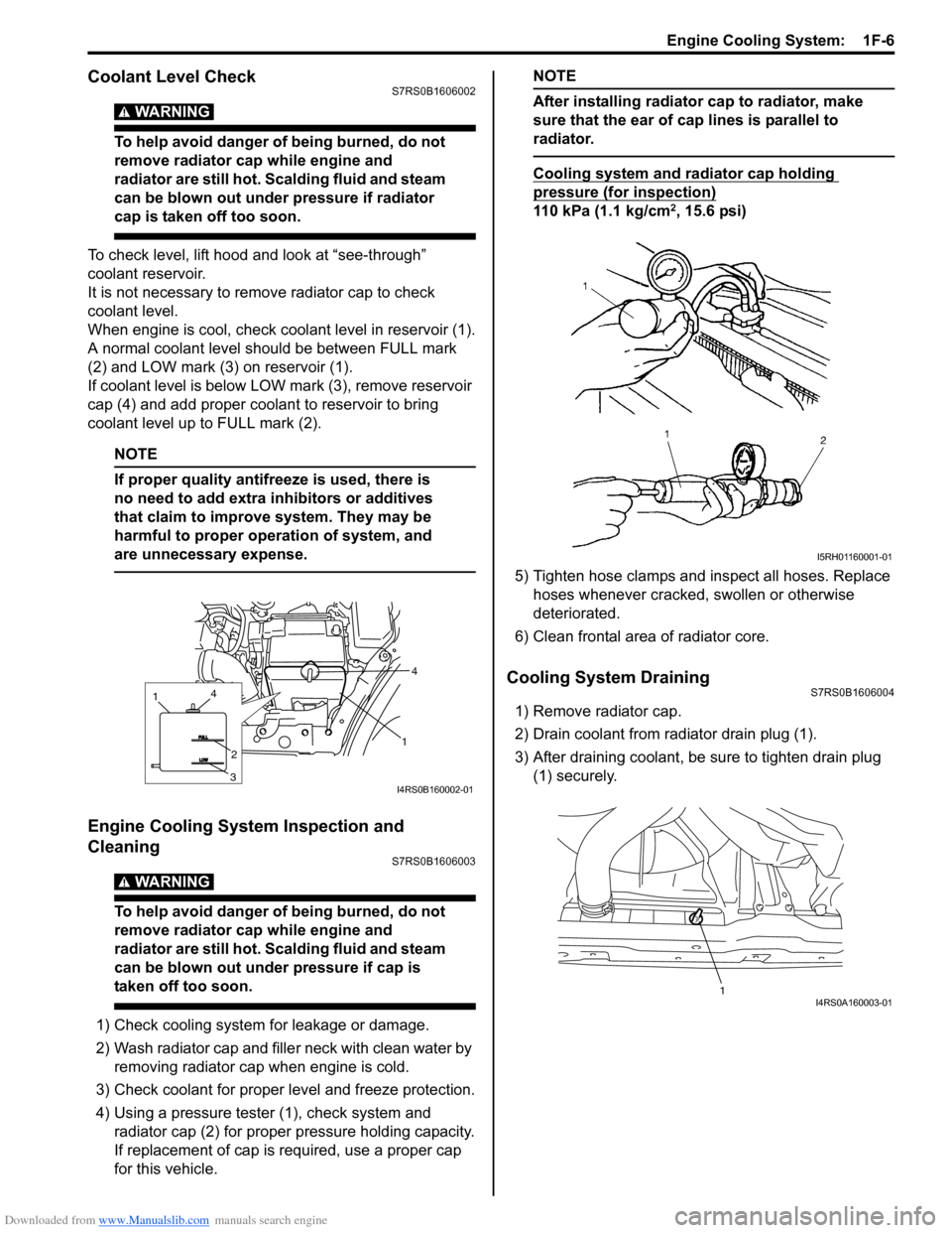
When engine is cool, check coolant level in reservoir (1).
A normal coolant level should be between FULL mark
(2) and LOW mark (3) on reservoir (1).
If coolant level is below LOW mark (3), remove reservoir
cap (4) and add proper coolant to reservoir to bring
coolant level up to FULL mark (2).
NOTE
If proper quality antifreeze is used, there is
no need to add extra inhibitors or additives
that claim to improve system. They may be
harmful to proper operation of system, and
are unnecessary expense.
Engine Cooling System Inspection and
Cleaning
S7RS0B1606003
WARNING!
To help avoid danger of being burned, do not
remove radiator cap while engine and
radiator are still hot. Scalding fluid and steam
can be blown out under pressure if cap is
taken off too soon.
1) Check cooling system for leakage or damage.
2) Wash radiator cap and fille r neck with clean water by
removing radiator cap when engine is cold.
3) Check coolant for proper level and freeze protection.
4) Using a pressure tester (1), check system and radiator cap (2) for proper pressure holding capacity.
If replacement of cap is required, use a proper cap
for this vehicle.
NOTE
After installing radiator cap to radiator, make
sure that the ear of cap lines is parallel to
radiator.
Cooling system and radiator cap holding
pressure (for inspection)
110 kPa (1.1 kg/cm2, 15.6 psi)
5) Tighten hose clamps and inspect all hoses. Replace hoses whenever cracked, swollen or otherwise
deteriorated.
6) Clean frontal area of radiator core.
Cooling System DrainingS7RS0B1606004
1) Remove radiator cap.
2) Drain coolant from radiator drain plug (1).
3) After draining coolant, be sure to tighten drain plug (1) securely.
1
4
1
3
2
4
I4RS0B160002-01
I5RH01160001-01
1I4RS0A160003-01
Page 370 of 1496
Downloaded from www.Manualslib.com manuals search engine 1F-7 Engine Cooling System:
Cooling System Flush and RefillS7RS0B1606005
WARNING!
To help avoid danger of being burned, do not
remove radiator cap while engine and
radiator are still hot. Scalding fluid and steam
can be blown out under pressure if cap is
taken off too soon.
NOTE
For detail of coolant specification, refer to
“Coolant Description”.
1) Remove radiator cap when engine is cool as follows.a) Turn cap counterclockwise slowly until it reaches a “stop” (Do not press down while turning it).
b) Wait until pressure is relieved (indicated by a hissing sound) then press down on cap and
continue to turn it counterclockwise.
2) With radiator cap removed, run engine until upper radiator hose is hot (this shows that thermostat is
open and coolant is flowing through system).
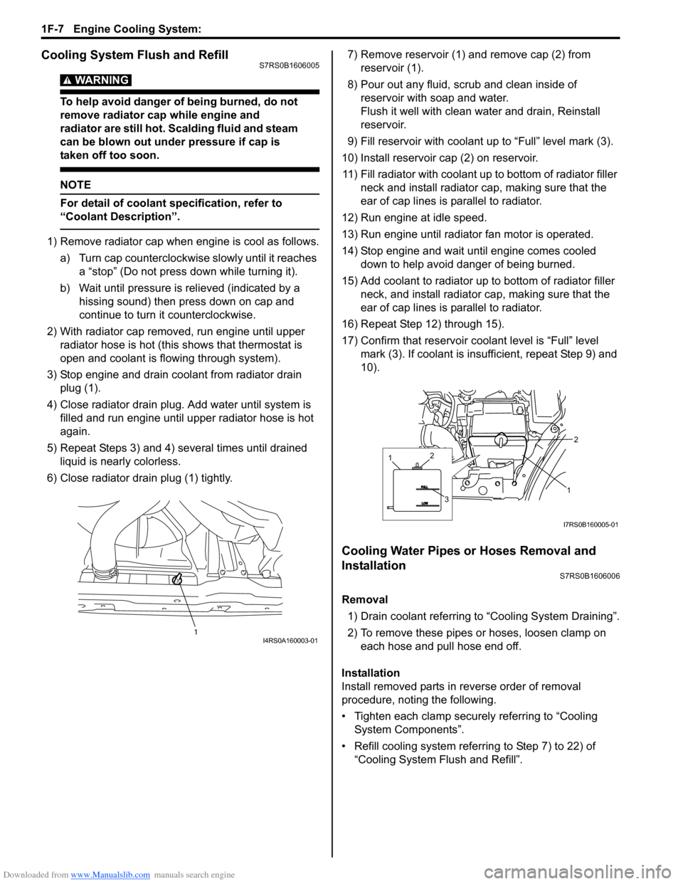
3) Stop engine and drain coolant from radiator drain plug (1).
4) Close radiator drain plug. Add water until system is filled and run engine until up per radiator hose is hot
again.
5) Repeat Steps 3) and 4) several times until drained liquid is nearly colorless.
6) Close radiator drain plug (1) tightly. 7) Remove reservoir (1) and remove cap (2) from
reservoir (1).
8) Pour out any fluid, scrub and clean inside of reservoir with soap and water.
Flush it well with clean water and drain, Reinstall
reservoir.
9) Fill reservoir with coolant up to “Full” level mark (3).
10) Install reservoir cap (2) on reservoir. 11) Fill radiator with coolant up to bottom of radiator filler neck and install radiator cap, making sure that the
ear of cap lines is parallel to radiator.
12) Run engine at idle speed.
13) Run engine until radiator fan motor is operated.
14) Stop engine and wait until engine comes cooled down to help avoid danger of being burned.
15) Add coolant to radiator up to bottom of radiator filler
neck, and install radiator ca p, making sure that the
ear of cap lines is parallel to radiator.
16) Repeat Step 12) through 15).
17) Confirm that reservoir cool ant level is “Full” level
mark (3). If coolant is insu fficient, repeat Step 9) and
10).
Cooling Water Pipes or Hoses Removal and
Installation
S7RS0B1606006
Removal
1) Drain coolant referring to “Cooling System Draining”.
2) To remove these pipes or hoses, loosen clamp on each hose and pull hose end off.
Installation
Install removed parts in reverse order of removal
procedure, noting the following.
• Tighten each clamp securely referring to “Cooling System Components”.
• Refill cooling system referrin g to Step 7) to 22) of
“Cooling System Flush and Refill”.
1I4RS0A160003-01
1
2
1
3
2
I7RS0B160005-01
Page 389 of 1496

Downloaded from www.Manualslib.com manuals search engine Fuel System: 1G-14
Fuel Tank Purging ProcedureS7RS0B1706015
WARNING!
• Before starting the following procedure, be sure to observe “Precautions on Fuel
System Service” in order to reduce the risk
or fire and personal injury.
• This purging procedure will not remove all fuel vapor.
Do not attempt any repair on tank using
heat of flame as an explosion resulting in
personal injury could occur.
CAUTION!
Never remain water in fu el tank after washing,
or fuel tank inside will get corrosion.
The following procedure are used for purging fuel tank.
1) After removing fuel tank, remove all hoses, pipes and fuel pump assembly from fuel tank.
2) Drain all remaining fuel from tank.
3) Place fuel tank to flushing area.
4) Fill tank with warm water or tap water, and agitate
vigorously and drain. Repeat this washing until
inside of tank is clean. Replace tank if its inside is
rusty.
5) Completely flush out rema ining water after washing.
Fuel Pump On-Vehicle InspectionS7RS0B1706016
WARNING!
Before starting the following procedure, be
sure to observe “Precautions on Fuel System
Service” in order to reduce the risk or fire
and personal injury.
NOTE
The fuel pressure regulator is incorporated
with the fuel pump assembly so individual
inspection of it is impossible.
1) Remove filler cap and turn ON ignition switch (2).
Then fuel pump operating sound should be heard
from fuel filler (1) for about 2 seconds and stop. Be
sure to reinstall fuel filler cap after checking.
If the check result is not satisfactory, go to “Fuel
Pump and Its Circuit Check in Section 1A”. 2) Turn OFF ignition switch and leave over 10 minutes
as it is.
3) Fuel pressure should be felt at fuel feed hose (1) for about 2 seconds after ignition switch ON.
If fuel pressure is not felt, go to “Fuel Pressure
Check in Section 1A”.
Fuel Pump Assembly Removal and InstallationS7RS0B1706017
WARNING!
Before starting the following procedure, be
sure to observe “Precautions on Fuel System
Service” in order to reduce the risk or fire
and personal injury.
Removal
1) Remove fuel tank from vehicle. Refer to “Fuel Tank Removal and Installation”.
2) Disconnect fuel feed pipe (1) from fuel pump assembly (2) referring to “Fuel Hose Disconnecting
and Reconnecting”.
IVSY01170013-01
1I3RM0A170019-01
1
2
I6RS0C170008-02
Page 503 of 1496
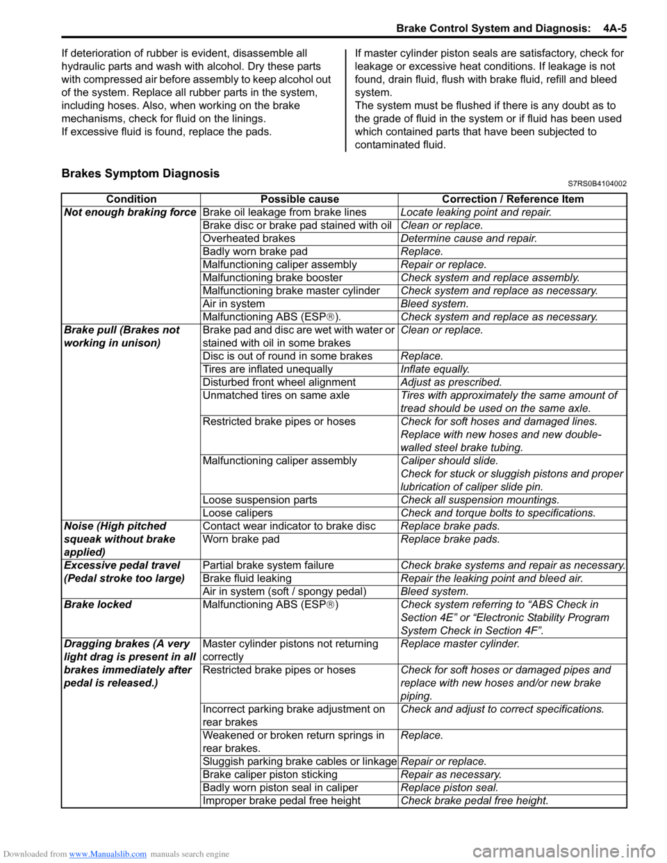
Downloaded from www.Manualslib.com manuals search engine Brake Control System and Diagnosis: 4A-5
If deterioration of rubber is evident, disassemble all
hydraulic parts and wash with alcohol. Dry these parts
with compressed air before assembly to keep alcohol out
of the system. Replace all rubber parts in the system,
including hoses. Also, when working on the brake
mechanisms, check for fluid on the linings.
If excessive fluid is found, replace the pads. If master cylinder piston seals
are satisfactory, check for
leakage or excessive heat co nditions. If leakage is not
found, drain fluid, flush with brake fluid, refill and bleed
system.
The system must be flushed if there is any doubt as to
the grade of fluid in the system or if fluid has been used
which contained parts that have been subjected to
contaminated fluid.
Brakes Symptom DiagnosisS7RS0B4104002
Condition Possible cause Correction / Reference Item
Not enough braking force Brake oil leakage from brake lines Locate leaking point and repair.
Brake disc or brake pad stained with oil Clean or replace.
Overheated brakes Determine cause and repair.
Badly worn brake pad Replace.
Malfunctioning caliper assembly Repair or replace.
Malfunctioning brake booster Check system and replace assembly.
Malfunctioning brake master cylinder Check system and replace as necessary.
Air in system Bleed system.
Malfunctioning ABS (ESP ®). Check system and replace as necessary.
Brake pull (Brakes not
working in unison) Brake pad and disc are wet with water or
stained with oil in some brakes Clean or replace.
Disc is out of round in some brakes Replace.
Tires are inflated unequally Inflate equally.
Disturbed front wheel alignment Adjust as prescribed.
Unmatched tires on same axle Tires with approximately the same amount of
tread should be used on the same axle.
Restricted brake pipes or hoses Check for soft hoses and damaged lines.
Replace with new hoses and new double-
walled steel brake tubing.
Malfunctioning caliper assembly Caliper should slide.
Check for stuck or sluggish pistons and proper
lubrication of caliper slide pin.
Loose suspension parts Check all suspension mountings.
Loose calipers Check and torque bolts to specifications.
Noise (High pitched
squeak without brake
applied) Contact wear indicator to brake disc
Replace brake pads.
Worn brake pad Replace brake pads.
Excessive pedal travel
(Pedal stroke too large) Partial brake system failure
Check brake systems and repair as necessary.
Brake fluid leaking Repair the leaking point and bleed air.
Air in system (soft / spongy pedal) Bleed system.
Brake locked Malfunctioning ABS (ESP®) Check system referri ng to “ABS Check in
Section 4E” or “Electronic Stability Program
System Check in Section 4F”.
Dragging brakes (A very
light drag is present in all
brakes immediately after
pedal is released.) Master cylinder pistons not returning
correctly
Replace master cylinder.
Restricted brake pipes or hoses Check for soft hoses or damaged pipes and
replace with new hoses and/or new brake
piping.
Incorrect parking brake adjustment on
rear brakes Check and adjust to correct specifications.
Weakened or broken return springs in
rear brakes. Replace.
Sluggish parking brake cables or linkage Repair or replace.
Brake caliper piston sticking Repair as necessary.
Badly worn piston seal in caliper Replace piston seal.
Improper brake pedal free height Check brake pedal free height.