2007 SUZUKI SWIFT Storing
[x] Cancel search: StoringPage 663 of 1496
Downloaded from www.Manualslib.com manuals search engine Automatic Transmission/Transaxle: 5A-19
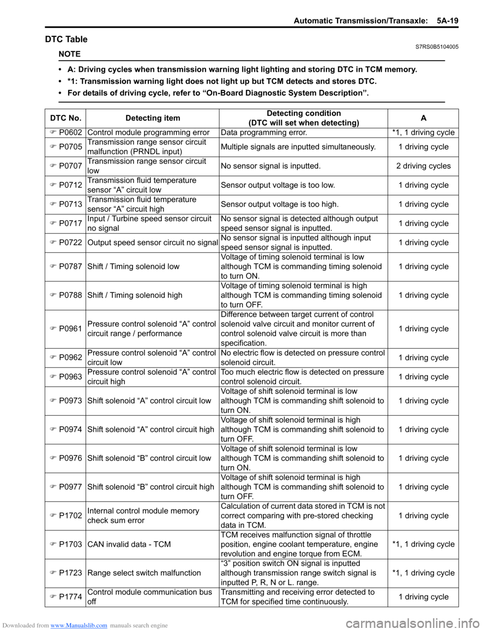
DTC TableS7RS0B5104005
NOTE
• A: Driving cycles when transmission warning light lighting and storing DTC in TCM memory.
• *1: Transmission warning light does not light up but TCM detects and stores DTC.
• For details of driving cycle, refer to “On-Board Diagnostic System Description”.
DTC No.Detecting item Detecting condition
(DTC will set when detecting) A
�) P0602 Control module programming error D ata programming error. *1, 1 driving cycle
�) P0705 Transmission range sensor circuit
malfunction (PRNDL input) Multiple signals are inputted
simultaneously. 1 driving cycle
�) P0707 Transmission range sensor circuit
low No sensor signal is inputted.
2 driving cycles
�) P0712 Transmission fluid temperature
sensor “A” circuit low Sensor output voltage is too low.
1 driving cycle
�) P0713 Transmission fluid temperature
sensor “A” circuit high Sensor output voltage is too high.
1 driving cycle
�) P0717 Input / Turbine speed sensor circuit
no signal No sensor signal is detected although output
speed sensor signal is inputted.
1 driving cycle
�) P0722 Output speed sensor circuit no signal No sensor signal is inputted although input
speed sensor signal is inputted. 1 driving cycle
�) P0787 Shift / Timing solenoid low Voltage of timing solenoid terminal is low
although TCM is commanding timing solenoid
to turn ON. 1 driving cycle
�) P0788 Shift / Timing solenoid high Voltage of timing solenoid terminal is high
although TCM is commanding timing solenoid
to turn OFF. 1 driving cycle
�) P0961 Pressure control solenoid “A” control
circuit range / performance Difference between target current of control
solenoid valve circuit and monitor current of
control solenoid valve circuit is more than
specification.
1 driving cycle
�) P0962 Pressure control solenoid “A” control
circuit low No electric flow is detected on pressure control
solenoid circuit.
1 driving cycle
�) P0963 Pressure control solenoid “A” control
circuit high Too much electric flow is detected on pressure
control solenoid circuit.
1 driving cycle
�) P0973 Shift solenoid “A” control circuit low Voltage of shift solenoid terminal is low
although TCM is commanding shift solenoid to
turn ON. 1 driving cycle
�) P0974 Shift solenoid “A” control circuit high Voltage of shift solenoid terminal is high
although TCM is commanding shift solenoid to
turn OFF. 1 driving cycle
�) P0976 Shift solenoid “B” control circuit low Voltage of shift solenoid terminal is low
although TCM is commanding shift solenoid to
turn ON. 1 driving cycle
�) P0977 Shift solenoid “B” control circuit high Voltage of shift solenoid terminal is high
although TCM is commanding shift solenoid to
turn OFF. 1 driving cycle
�) P1702 Internal control module memory
check sum error Calculation of current data stored in TCM is not
correct comparing with pre-stored checking
data in TCM.
1 driving cycle
�) P1703 CAN invalid data - TCM TCM receives malfunction signal of throttle
position
, engine coolan t temperature, engine
revolution and engine torque from ECM. *1, 1 driving cycle
�) P1723 Range select switch malfunction “3” position switch ON signal is inputted
although transmission range switch signal is
inputted P, R, N or L. range. *1, 1 driving cycle
�) P1774 Control module communication bus
off Transmitting and receiving error detected to
TCM for specified time continuously.
1 driving cycle
Page 1040 of 1496
Downloaded from www.Manualslib.com manuals search engine 8B-2 Air Bag System:
Precautions on Handling and Storage of Air Bag
System Components
S7RS0B8200002
SDM
WARNING!
Never power up air bag system when SDM is
not rigidly attached to the vehicle. Otherwise,
personal injury may result.
CAUTION!
After detecting one time of such collision as
to meet deployment conditions, SDM must
not be used. Refer to “Air Bag Diagnostic
System Check” when checking SDM.
• Never attempt disassembly of SDM.
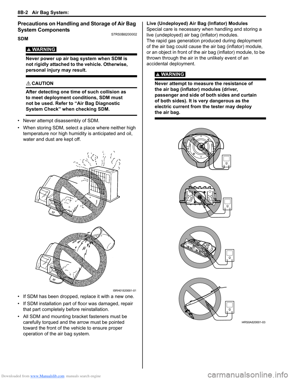
• When storing SDM, select a place where neither high temperature nor high humidity is anticipated and oil,
water and dust are kept off.
• If SDM has been dropped, replace it with a new one.
• If SDM installation part of floor was damaged, repair that part completely before reinstallation.
• All SDM and mounting bracket fasteners must be carefully torqued and the arrow must be pointed
toward the front of the vehicle to ensure proper
operation of the air bag system. Live (Undeployed) Air Bag (Inflator) Modules
Special care is necessary when handling and storing a
live (undeployed) air bag (inflator) modules.
The rapid gas generation produced during deployment
of the air bag could cause the air bag (inflator) module,
or an object in front of the air bag (inflator) module, to be
thrown through the air in the unlikely event of an
accidental deployment.
WARNING!
Never attempt to measure the resistance of
the air bag (inflator) modules (driver,
passenger and side of both sides and curtain
of both sides). It is
very dangerous as the
electric current from the tester may deploy
the air bag.
I5RH01820001-01
I4RS0A820001-03
Page 1041 of 1496
Downloaded from www.Manualslib.com manuals search engine Air Bag System: 8B-3
• Never attempt disassembly of the air bag (inflator) modules.
• If any abnormality is found, be sure to replace it with
new one as an assembly.
• When an abnormality is noted as existing in the live (undeployed) air bag (inflator) module, be sure to
deploy it before discarding it.
• When grease, cleaning agent, oil, water, etc., got on the air bag (inflator) modules (driver, passenger, side
of both sides and curtain of both sides), wipe it off
immediately with a dry cloth.
• If air bag (inflator) module was dropped from a height of 90 cm (3 ft) or more, it should be replaced with a
new one as an assembly.
WARNING!
• For handling and storage of a live air bag (inflator) module, select a place where the
ambient temperature below 65 °C (150 ° F),
without high humidity and away from
electric noise.
• When carrying a live air bag (inflator) module, make sure the bag opening is
pointed away from you. In case of an
accidental deployment, the bag will then
deploy with minimal chance of injury.
Never carry the air bag (inflator) module by
the wires or connector on the underside of
the module.
Otherwise, personal injury may result.
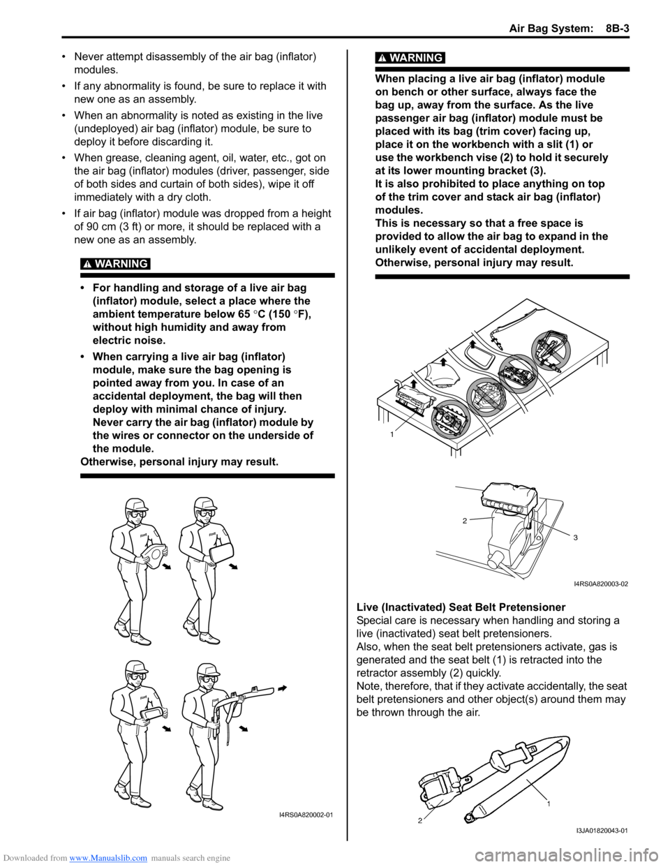
WARNING!
When placing a live air bag (inflator) module
on bench or other surface, always face the
bag up, away from the surface. As the live
passenger air bag (inflator) module must be
placed with its bag (trim cover) facing up,
place it on the workbench with a slit (1) or
use the workbench vise (2) to hold it securely
at its lower mounting bracket (3).
It is also prohibited to place anything on top
of the trim cover and stack air bag (inflator)
modules.
This is necessary so that a free space is
provided to allow the air bag to expand in the
unlikely event of accidental deployment.
Otherwise, personal injury may result.
Live (Inactivated) Seat Belt Pretensioner
Special care is necessary when handling and storing a
live (inactivated) seat belt pretensioners.
Also, when the seat belt pretensioners activate, gas is
generated and the seat belt (1) is retracted into the
retractor assembly (2) quickly.
Note, therefore, that if they activate accidentally, the seat
belt pretensioners and other object(s) around them may
be thrown through the air.
I4RS0A820002-01
1
2
3
I4RS0A820003-02
I3JA01820043-01
Page 1140 of 1496
Downloaded from www.Manualslib.com manuals search engine 8B-102 Air Bag System:
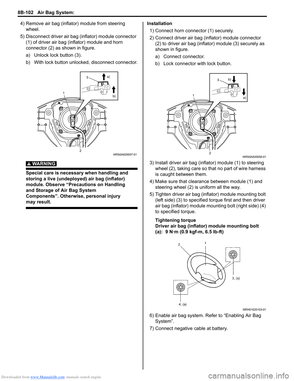
4) Remove air bag (inflator) module from steering wheel.
5) Disconnect driver air bag (inflator) module connector (1) of driver air bag (inflator) module and horn
connector (2) as shown in figure.
a) Unlock lock button (3).
b) With lock button unlocked, disconnect connector.
WARNING!
Special care is necessary when handling and
storing a live (undeployed) air bag (inflator)
module. Observe “Precautions on Handling
and Storage of Air Bag System
Components”. Otherwise, personal injury
may result.
Installation
1) Connect horn connector (1) securely.
2) Connect driver air bag (inflator) module connector (2) to driver air bag (inflator) module (3) securely as
shown in figure.
a) Connect connector.
b) Lock connector with lock button.
3) Install driver air bag (inflator) module (1) to steering wheel (2), taking care so t hat no part of wire harness
is caught between them.
4) Make sure that clearance between module (1) and steering wheel (2) is uniform all the way.
5) Tighten driver air bag (inflator) module mounting bolt (left side) (3) to specified torque first and then driver
air bag (inflator) module mounting bolt (right side) (4)
to specified torque.
Tightening torque
Driver air bag (inflator) module mounting bolt
(a): 9 N·m (0.9 kgf-m, 6.5 lb-ft)
6) Enable air bag system. Refer to “Enabling Air Bag System”.
7) Connect negative cable at battery.
1
2
3 a)
b)
I4RS0A820057-01
1
2
3 a)
b)
I4RS0A820058-01
I5RH01820103-01
Page 1142 of 1496
Downloaded from www.Manualslib.com manuals search engine 8B-104 Air Bag System:
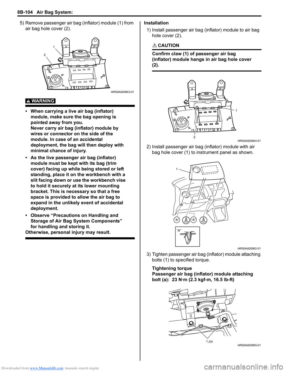
5) Remove passenger air bag (inflator) module (1) from air bag hole cover (2).
WARNING!
• When carrying a live air bag (inflator) module, make sure the bag opening is
pointed away from you.
Never carry air bag (inflator) module by
wires or connector on the side of the
module. In case of an accidental
deployment, the bag will then deploy with
minimal chance of injury.
• As the live passenger air bag (inflator) module must be kept with its bag (trim
cover) facing up while being stored or left
standing, place it on the workbench with a
slit facing down or use the workbench vise
to hold it securely at its lower mounting
bracket. This is necessary so that a free
space is provided to allow the air bag to
expand in the unlikely event of accidental
deployment.
• Observe “Precautions on Handling and Storage of Air Bag System Components”
for handling and storing it.
Otherwise, personal injury may result.
Installation
1) Install passenger air bag (inflator) module to air bag hole cover (2).
CAUTION!
Confirm claw (1) of passenger air bag
(inflator) module hangs in air bag hole cover
(2).
2) Install passenger air bag (inflator) module with air bag hole cover (1) to instrument panel as shown.
3) Tighten passenger air bag (inflator) module attaching bolts (1) to sp ecified torque.
Tightening torque
Passenger air bag (inflator) module attaching
bolt (a): 23 N·m (2.3 kgf-m, 16.5 lb-ft)
1
2
I4RS0A820063-01
2 1I4RS0A820064-01
“A”
“A”“A”
1
I4RS0A820062-01
1,(a)I4RS0A820065-01
Page 1144 of 1496
Downloaded from www.Manualslib.com manuals search engine 8B-106 Air Bag System:
4) Remove side-air bag (inflator) module from seat back.
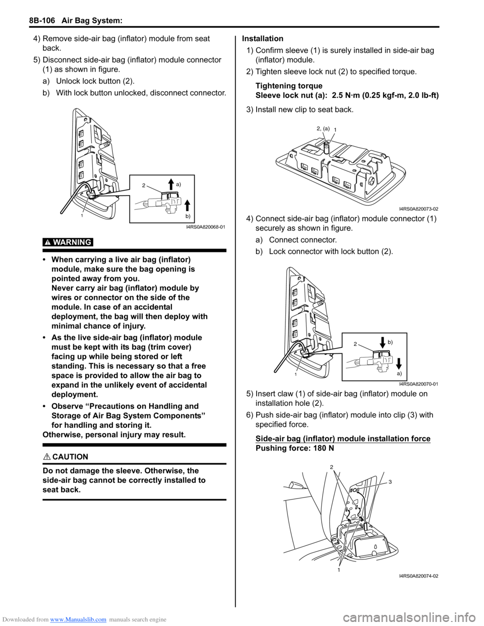
5) Disconnect side-air bag (inflator) module connector (1) as shown in figure.
a) Unlock lock button (2).
b) With lock button unlocked, disconnect connector.
WARNING!
• When carrying a live air bag (inflator) module, make sure the bag opening is
pointed away from you.
Never carry air bag (inflator) module by
wires or connector on the side of the
module. In case of an accidental
deployment, the bag will then deploy with
minimal chance of injury.
• As the live side-air bag (inflator) module must be kept with its bag (trim cover)
facing up while being stored or left
standing. This is necessary so that a free
space is provided to allow the air bag to
expand in the unlikely event of accidental
deployment.
• Observe “Precautions on Handling and Storage of Air Bag System Components”
for handling and storing it.
Otherwise, personal injury may result.
CAUTION!
Do not damage the sleeve. Otherwise, the
side-air bag cannot be correctly installed to
seat back.
Installation
1) Confirm sleeve (1) is surely installed in side-air bag (inflator) module.
2) Tighten sleeve lock nut (2) to specified torque.
Tightening torque
Sleeve lock nut (a): 2.5 N·m (0.25 kgf-m, 2.0 lb-ft)
3) Install new clip to seat back.
4) Connect side-air bag (inflator) module connector (1) securely as shown in figure.
a) Connect connector.
b) Lock connector wi th lock button (2).
5) Insert claw (1) of side-air bag (inflator) module on installation hole (2).
6) Push side-air bag (inflator) module into clip (3) with
specified force.
Side-air bag (inflator) module installation force
Pushing force: 180 N
2
1
a)
b)
I4RS0A820068-01
12, (a)
I4RS0A820073-02
1
2 a)
b)
I4RS0A820070-01
1
2
3
I4RS0A820074-02
Page 1146 of 1496
Downloaded from www.Manualslib.com manuals search engine 8B-108 Air Bag System:
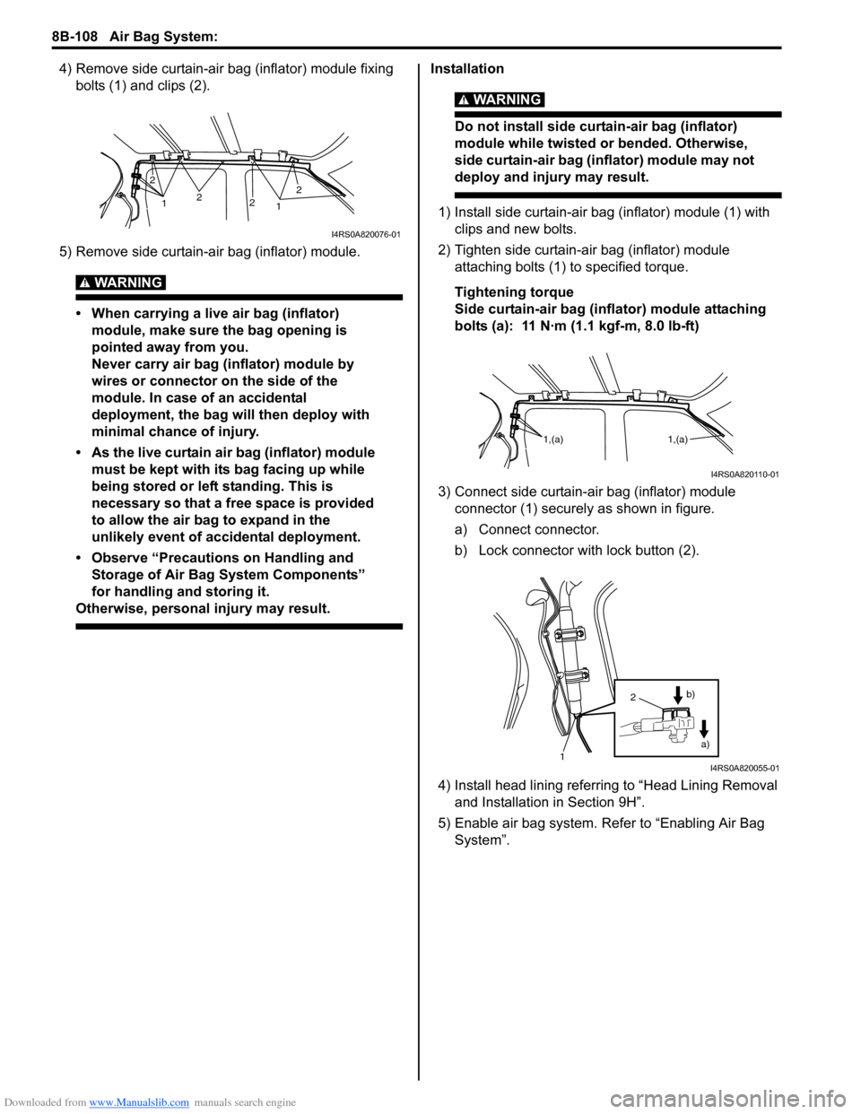
4) Remove side curtain-air bag (inflator) module fixing bolts (1) and clips (2).
5) Remove side curtain-air bag (inflator) module.
WARNING!
• When carrying a live air bag (inflator) module, make sure the bag opening is
pointed away from you.
Never carry air bag (inflator) module by
wires or connector on the side of the
module. In case of an accidental
deployment, the bag will then deploy with
minimal chance of injury.
• As the live curtain air bag (inflator) module must be kept with it s bag facing up while
being stored or left standing. This is
necessary so that a free space is provided
to allow the air bag to expand in the
unlikely event of accidental deployment.
• Observe “Precautions on Handling and Storage of Air Bag System Components”
for handling and storing it.
Otherwise, personal injury may result.
Installation
WARNING!
Do not install side curtain-air bag (inflator)
module while twisted or bended. Otherwise,
side curtain-air bag (inflator) module may not
deploy and injury may result.
1) Install side curtain-air bag (inflator) module (1) with
clips and new bolts.
2) Tighten side curtain-air bag (inflator) module attaching bolts (1) to specified torque.
Tightening torque
Side curtain-air bag (inflator) module attaching
bolts (a): 11 N·m (1.1 kgf-m, 8.0 lb-ft)
3) Connect side curtain-air bag (inflator) module connector (1) securely as shown in figure.
a) Connect connector.
b) Lock connector wi th lock button (2).
4) Install head lining referring to “Head Lining Removal and Installation in Section 9H”.
5) Enable air bag system. Refer to “Enabling Air Bag System”.1 2
2
22
1
I4RS0A820076-01
1,(a) 1,(a)
I4RS0A820110-01
1
2
a)
b)
I4RS0A820055-01
Page 1152 of 1496
Downloaded from www.Manualslib.com manuals search engine 8B-114 Air Bag System:
Deployment / Activation Outside of Vehicle
When you intend to return the vehicle to service, deploy
the air bag (inflator) module(s) or activate seat belt
pretensioner(s) outside of the vehicle.1) Turn ignition switch to LOCK position and remove key.
2) Wear safety glasses during this deployment / activation procedure.
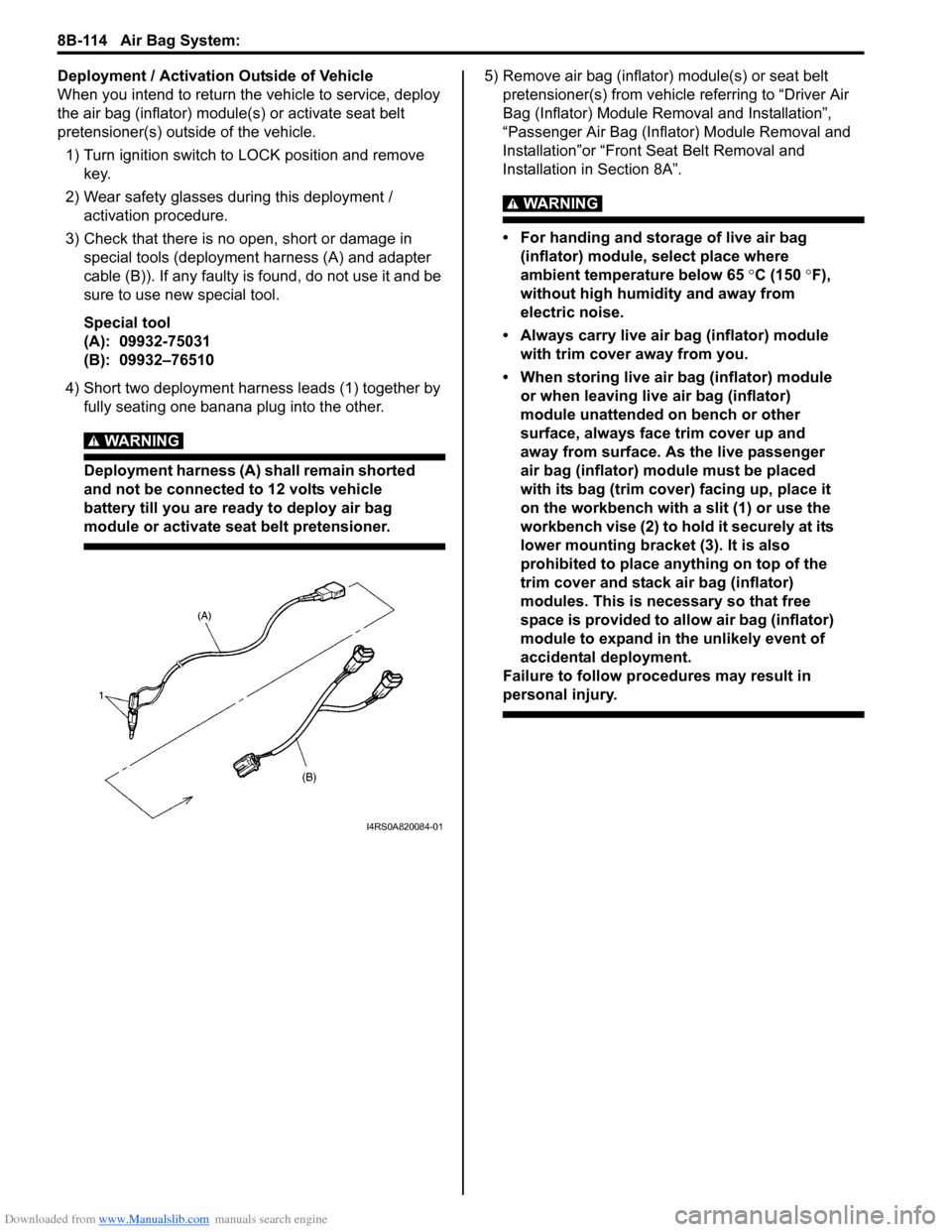
3) Check that there is no open, short or damage in special tools (deployment harness (A) and adapter
cable (B)). If any faulty is found, do not use it and be
sure to use new special tool.
Special tool
(A): 09932-75031
(B): 09932–76510
4) Short two deployment harness leads (1) together by fully seating one banana plug into the other.
WARNING!
Deployment harness (A) shall remain shorted
and not be connected to 12 volts vehicle
battery till you are ready to deploy air bag
module or activate seat belt pretensioner.
5) Remove air bag (inflator) module(s) or seat belt pretensioner(s) from vehicle referring to “Driver Air
Bag (Inflator) Module Re moval and Installation”,
“Passenger Air Bag (Inflator) Module Removal and
Installation”or “Front Seat Belt Removal and
Installation in Section 8A”.
WARNING!
• For handing and storage of live air bag (inflator) module, select place where
ambient temperature below 65 °C (150 °F),
without high humidity and away from
electric noise.
• Always carry live air bag (inflator) module with trim cover away from you.
• When storing live air bag (inflator) module or when leaving live air bag (inflator)
module unattended on bench or other
surface, always face trim cover up and
away from surface. As the live passenger
air bag (inflator) module must be placed
with its bag (trim cover) facing up, place it
on the workbench with a slit (1) or use the
workbench vise (2) to hold it securely at its
lower mounting bracket (3). It is also
prohibited to place anything on top of the
trim cover and stack air bag (inflator)
modules. This is necessary so that free
space is provided to allow air bag (inflator)
module to expand in the unlikely event of
accidental deployment.
Failure to follow procedures may result in
personal injury.
I4RS0A820084-01