2007 SUZUKI SWIFT Far
[x] Cancel search: FarPage 12 of 1496
Downloaded from www.Manualslib.com manuals search engine 00-7 Precautions:
Warning for Wheel (with tire) RemovalS7RS0B0000003
WARNING!
When removing any of these wheels installed
with wheel bolts, never remove all wheel
bolts at the same time. Leave at least 1 bolt
for each wheel as it is to prevent wheel from
dropping. When removing this remaining 1
bolt, hold wheel and tire so as not to allow
them to come off.
Warning for Handling Emergency Flat Tire
Repair Kit
S7RS0B0000004
WARNING!
If vehicle is equipped with Emergency Flat
Tire Repair Kit instead of spare tire, be sure
to observe “Precaution for Emergency Flat
Tire Repair Kit in Section 2D” when handling
Emergency Flat Tire Repair Kit and repairing
flat tire.
Otherwise, your health may be ruined or it
will be impossible to repair flat tire.
Precautions for Catalytic ConverterS7RS0B0000005
For vehicles equipped with a catalytic converter, use
only unleaded gasoline and be careful not to let a large
amount of unburned gasoline enter the converter or it
can be damaged.
• Conduct a spark jump test only when necessary, make it as short as possible, and do not open the
throttle.
• Conduct engine compression checks within the shortest possible time.
• Avoid situations which can result in engine misfire (e.g. starting the engine when the fuel tank is nearly
empty.)
Precautions for Installing Mobile
Communication Equipment
S7RS0B0000006
When installing mobile communication equipment such
as CB (Citizens-Band)-radi o or cellular-telephone, be
sure to observe the following precautions.
Failure to follow cautions may adversely affect electronic
control system.
• Keep the antenna as far away as possible from the vehicle’s electronic control unit.
• Keep the antenna feeder more than 20 cm (7.9 in.) away from electronic control unit and its wire
harnesses.
• Do not run the antenna feeder parallel with other wire harnesses.
• Confirm that the antenna and feeder are correctly adjusted.
Precaution for CAN Communication SystemS7RS0B0000007
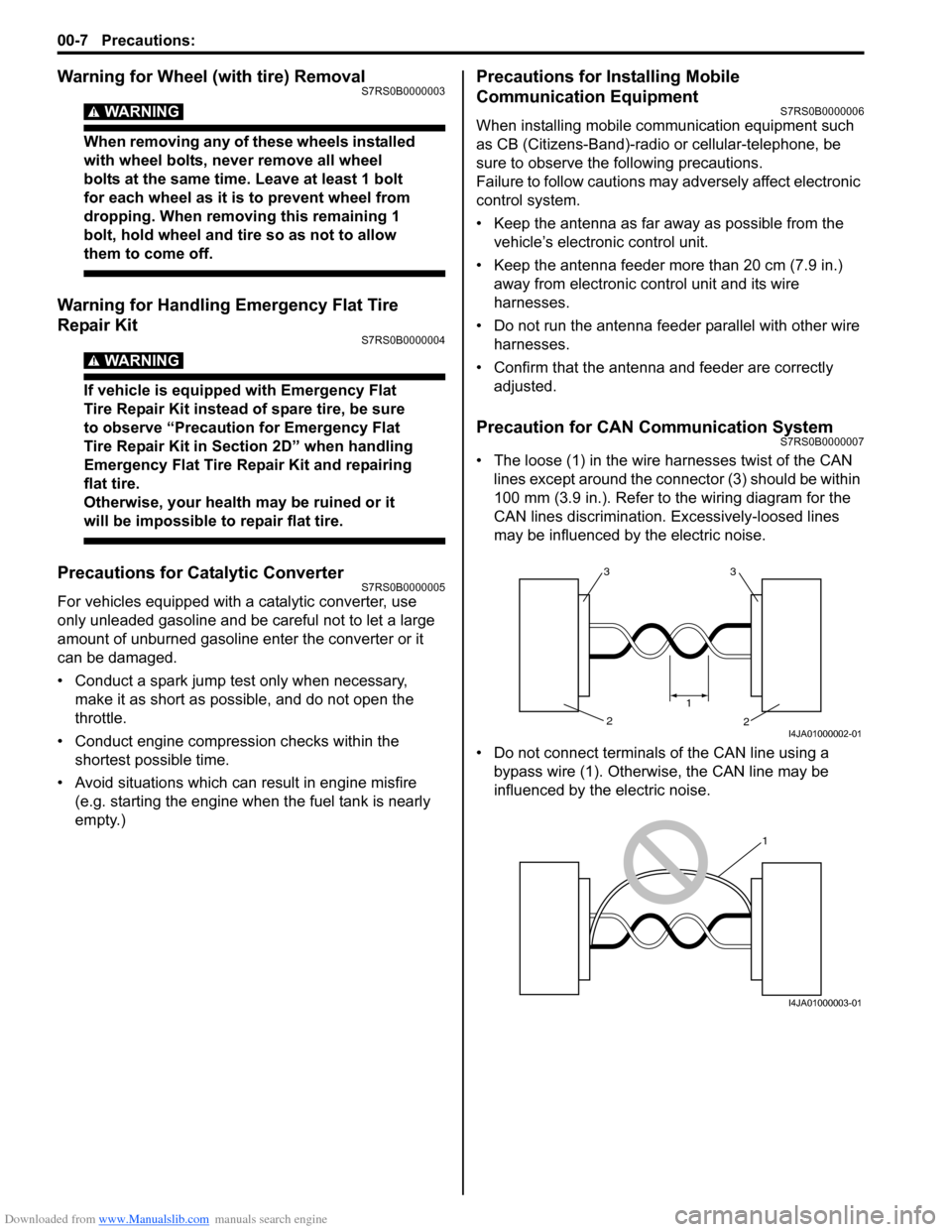
• The loose (1) in the wire harnesses twist of the CAN lines except around the connector (3) should be within
100 mm (3.9 in.). Refer to the wiring diagram for the
CAN lines discrimination. Excessively-loosed lines
may be influenced by the electric noise.
• Do not connect terminals of the CAN line using a bypass wire (1). Otherwise, the CAN line may be
influenced by the electric noise.
33
2
2
1
I4JA01000002-01
1
I4JA01000003-01
Page 19 of 1496
Downloaded from www.Manualslib.com manuals search engine Precautions: 00-14
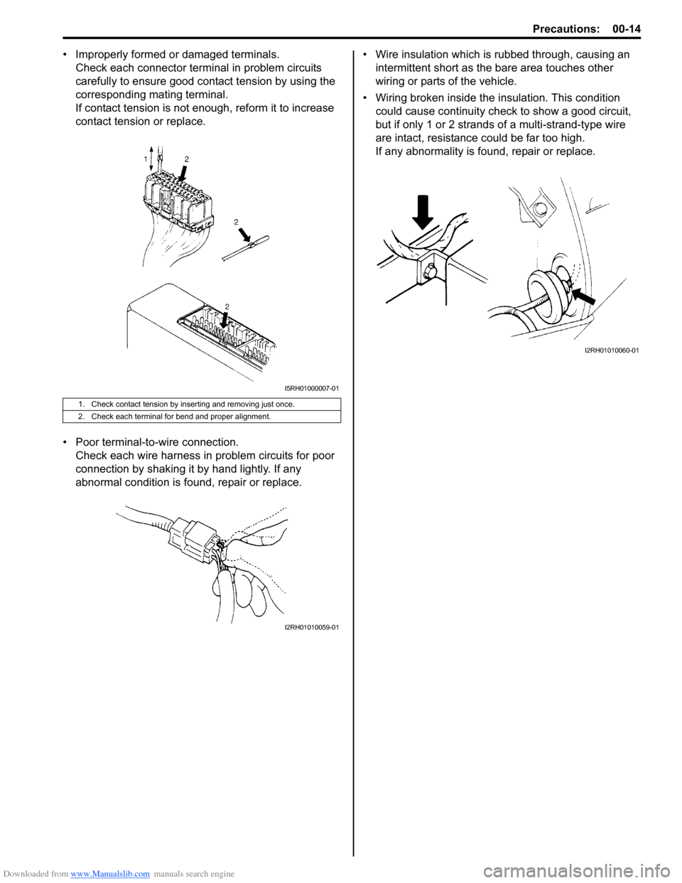
• Improperly formed or damaged terminals.Check each connector terminal in problem circuits
carefully to ensure good contact tension by using the
corresponding mating terminal.
If contact tension is not enough, reform it to increase
contact tension or replace.
• Poor terminal-to -wire connection.
Check each wire harness in problem circuits for poor
connection by shaking it by hand lightly. If any
abnormal condition is found, repair or replace. • Wire insulation which is rubbed through, causing an
intermittent short as the bare area touches other
wiring or parts of the vehicle.
• Wiring broken inside the insulation. This condition
could cause continuity check to show a good circuit,
but if only 1 or 2 strands of a multi-strand-type wire
are intact, resistance could be far too high.
If any abnormality is found, repair or replace.
1. Check contact tension by inserting and removing just once.
2. Check each terminal for bend and proper alignment.
I5RH01000007-01
I2RH01010059-01
I2RH01010060-01
Page 40 of 1496
Downloaded from www.Manualslib.com manuals search engine 0B-10 Maintenance and Lubrication:
Steering System InspectionS7RS0B0206024
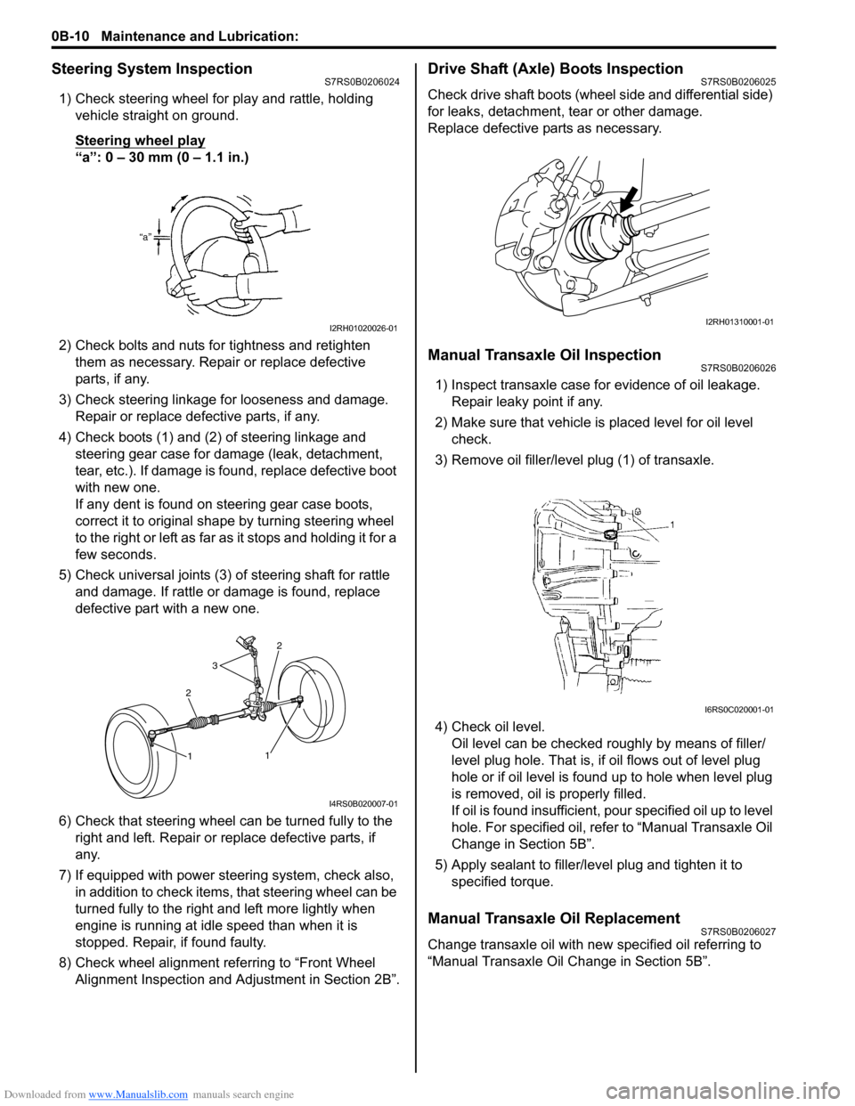
1) Check steering wheel for play and rattle, holding vehicle straight on ground.
Steering wheel play
“a”: 0 – 30 mm (0 – 1.1 in.)
2) Check bolts and nuts for tightness and retighten them as necessary. Repair or replace defective
parts, if any.
3) Check steering linkage for looseness and damage. Repair or replace defective parts, if any.
4) Check boots (1) and (2) of steering linkage and steering gear case for damage (leak, detachment,
tear, etc.). If damage is fo und, replace defective boot
with new one.
If any dent is found on steering gear case boots,
correct it to original shape by turning steering wheel
to the right or left as far as it stops and holding it for a
few seconds.
5) Check universal joints (3) of steering shaft for rattle and damage. If rattle or damage is found, replace
defective part with a new one.
6) Check that steering wheel can be turned fully to the
right and left. Repair or replace defective parts, if
any.
7) If equipped with power steering system, check also, in addition to check items, that steering wheel can be
turned fully to the right and left more lightly when
engine is running at idle speed than when it is
stopped. Repair, if found faulty.
8) Check wheel alignment referring to “Front Wheel Alignment Inspection and Adjustment in Section 2B”.
Drive Shaft (Axle) Boots InspectionS7RS0B0206025
Check drive shaft boots (wheel side and differential side)
for leaks, detachment, tear or other damage.
Replace defective parts as necessary.
Manual Transaxle Oil InspectionS7RS0B0206026
1) Inspect transaxle case for evidence of oil leakage. Repair leaky point if any.
2) Make sure that vehicle is placed level for oil level
check.
3) Remove oil filler/leve l plug (1) of transaxle.
4) Check oil level. Oil level can be checked roughly by means of filler/
level plug hole. That is, if oil flows out of level plug
hole or if oil level is found up to hole when level plug
is removed, oil is properly filled.
If oil is found insufficient, po ur specified oil up to level
hole. For specified oil, refe r to “Manual Transaxle Oil
Change in Section 5B”.
5) Apply sealant to filler/leve l plug and tighten it to
specified torque.
Manual Transaxle Oil ReplacementS7RS0B0206027
Change transaxle oil with new specified oil referring to
“Manual Transaxle Oil Change in Section 5B”.
I2RH01020026-01
2
3
2
1
1
I4RS0B020007-01
I2RH01310001-01
I6RS0C020001-01
Page 232 of 1496
Downloaded from www.Manualslib.com manuals search engine 1A-182 Engine General Information and Diagnosis:
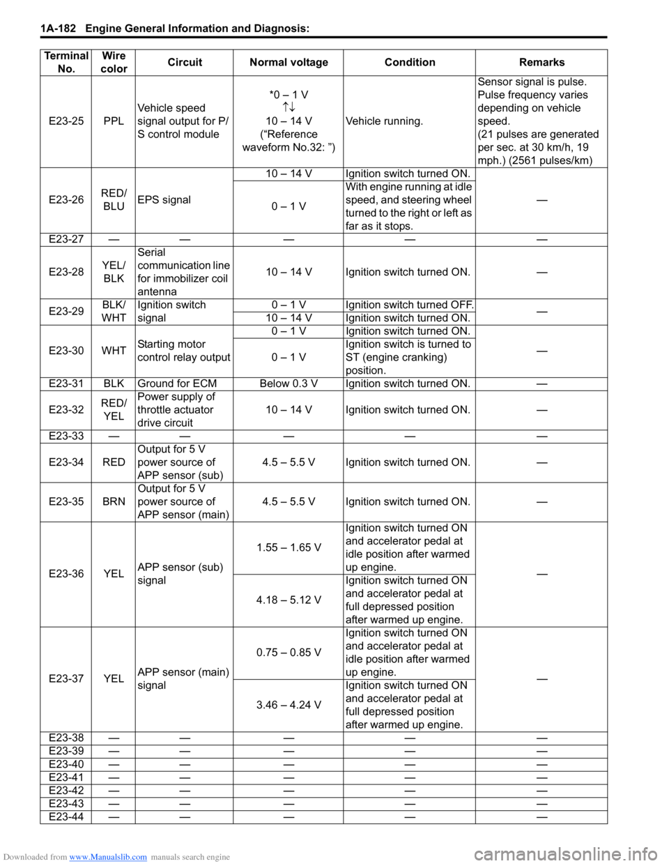
E23-25 PPLVehicle speed
signal output for P/
S control module *0 – 1 V
↑↓
10 – 14 V
(“Reference
waveform No.32: ”) Vehicle running. Sensor signal is pulse.
Pulse frequency varies
depending on vehicle
speed.
(21 pulses are generated
per sec. at 30 km/h, 19
mph.) (2561 pulses/km)
E23-26 RED/
BLU EPS signal 10 – 14 V Ignition switch turned ON.
—
0 – 1 V With engine running at idle
speed, and steering wheel
turned to the right or left as
far as it stops.
E23-27 — — — — —
E23-28 YEL/
BLK Serial
communication line
for immobilizer coil
antenna
10 – 14 V Ignition switch turned ON. —
E23-29 BLK/
WHT Ignition switch
signal 0 – 1 V Ignition switch turned OFF.
—
10 – 14 V Ignition switch turned ON.
E23-30 WHT Starting motor
control relay output 0 – 1 V Ignition switch turned ON.
—
0 – 1 V Ignition switch is turned to
ST (engine cranking)
position.
E23-31 BLK Ground for ECM Below 0.3 V Ignition switch turned ON. —
E23-32 RED/
YEL Power supply of
throttle actuator
drive circuit
10 – 14 V Ignition switch turned ON. —
E23-33 — — — — —
E23-34 RED Output for 5 V
power source of
APP sensor (sub) 4.5 – 5.5 V Ignition switch turned ON. —
E23-35 BRN Output for 5 V
power source of
APP sensor (main) 4.5 – 5.5 V Ignition switch turned ON. —
E23-36 YEL APP sensor (sub)
signal 1.55 – 1.65 V
Ignition switch turned ON
and accelerator pedal at
idle position after warmed
up engine.
—
4.18 – 5.12 V Ignition switch turned ON
and accelerator pedal at
full depressed position
after warmed up engine.
E23-37 YEL APP sensor (main)
signal 0.75 – 0.85 V
Ignition switch turned ON
and accelerator pedal at
idle position after warmed
up engine.
—
3.46 – 4.24 V Ignition switch turned ON
and accelerator pedal at
full depressed position
after warmed up engine.
E23-38 — — — — —
E23-39 — — — — —
E23-40 — — — — —
E23-41 — — — — —
E23-42 — — — — —
E23-43 — — — — —
E23-44 — — — — —
Terminal
No. Wire
color Circuit Normal voltage Condition Remarks
Page 381 of 1496

Downloaded from www.Manualslib.com manuals search engine Fuel System: 1G-6
Clamp other than around fuel tankFor Quick Joint
Disconnecting1) Remove mud, dust and/or foreign material between pipe (1) and quick joint (2) by blowing compressed
air.
2) Unlock joint lock by insert ing special tool between
pipe and quick joint.
Special tool
(A): 09919–47020
3) Disconnect quick joint from pipe.
Reconnecting
Insert quick joint to fuel pipe until they lock securely (a
click is heard), and confi rm that quick joint is not
disconnected by hand.
I3RM0A170001-01
[A]: With short pipe, fit hose as far as it reaches pipe joint as shown.
[B]: With the following type pipe, fit hose as far as its peripheral projection
as shown.
[C]: With bent pipe, fit hose as its bent part as shown or till depth “b”.
[D]: With straight pipe, fit hose till depth “b”.
[E]: With red marked pipe, fit hose end reaches red mark on pipe.
[F]: For fuel tank filler hose, insert it to spool or welding-bead.
“a”: Clamp securely at a position 3 – 7 mm (0.12 – 0.27 in.) from hose end.
“b”: 20 – 30 mm (0.79 – 1.18 in.) “c”: 0 – 5 mm (0 – 0.19 in.)
“d”: 5 – 12 mm (0.2 – 0.47 in.)
“e”: 40 mm (1.57 in.) 1. Pipe
2. Hose
3. Clamp
4. Red mark
1
2 1
2
(A)
I4RS0A170019-01
Page 440 of 1496
Downloaded from www.Manualslib.com manuals search engine 2B-7 Front Suspension:
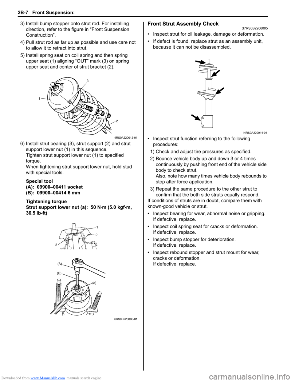
3) Install bump stopper onto strut rod. For installing
direction, refer to the figure in “Front Suspension
Construction”.
4) Pull strut rod as far up as possible and use care not to allow it to re tract into strut.
5) Install spring seat on coil spring and then spring upper seat (1) aligning “OUT” mark (3) on spring
upper seat and center of strut bracket (2).
6) Install strut bearing (3), strut support (2) and strut
support lower nut (1) in this sequence.
Tighten strut support lower nut (1) to specified
torque.
When tightening strut support lower nut, hold stud
with special tools.
Special tool
(A): 09900–00411 socket
(B): 09900–00414 6 mm
Tightening torque
Strut support lower nut (a): 50 N·m (5.0 kgf-m,
36.5 lb-ft)Front Strut Assembly CheckS7RS0B2206005
• Inspect strut for oil leakage, damage or deformation.
• If defect is found, replace strut as an assembly unit, because it can not be disassembled.
• Inspect strut function re ferring to the following
procedures:
1) Check and adjust tire pressures as specified.
2) Bounce vehicle body up and down 3 or 4 times continuously by pushing front end of the vehicle side
body to check strut.
Also, note how many times vehicle body rebounds to
stop after force application.
3) Repeat the same procedure to the other strut to confirm that the both side struts equally respond.
If conditions of struts are in doubt, compare them with
known-good vehicle or strut.
• Inspect bearing for wear, abnormal noise or gripping. If defective, replace.
• Inspect coil spring seat for cracks or deformation.
If defective, replace.
• Inspect bump stopper for deterioration. If defective, replace.
• Inspect rebound stopper and strut mount for wear, cracks or deformation.
If defective, replace.
I4RS0A220012-01
I6RS0B220006-01
I4RS0A220014-01
Page 458 of 1496
Downloaded from www.Manualslib.com manuals search engine 2C-4 Rear Suspension:
Rear Shock Absorber Bush Removal and
Installation
S7RS0B2306003
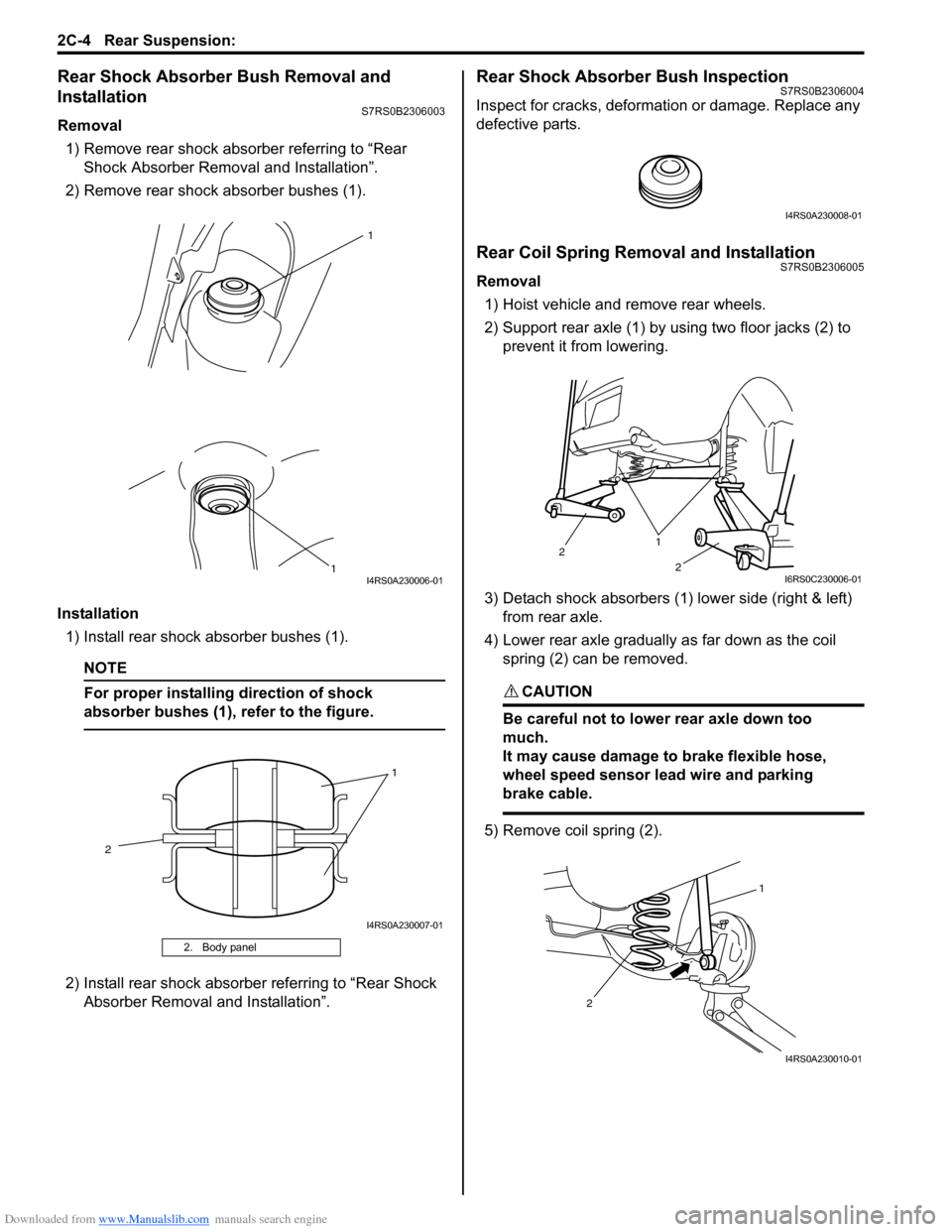
Removal1) Remove rear shock absorber referring to “Rear Shock Absorber Remova l and Installation”.
2) Remove rear shock absorber bushes (1).
Installation 1) Install rear shock absorber bushes (1).
NOTE
For proper installing direction of shock
absorber bushes (1), refer to the figure.
2) Install rear shock absorber referring to “Rear Shock Absorber Removal and Installation”.
Rear Shock Absorber Bush InspectionS7RS0B2306004
Inspect for cracks, deformation or damage. Replace any
defective parts.
Rear Coil Spring Removal and InstallationS7RS0B2306005
Removal
1) Hoist vehicle and remove rear wheels.
2) Support rear axle (1) by using two floor jacks (2) to prevent it from lowering.
3) Detach shock absorbers (1) lower side (right & left) from rear axle.
4) Lower rear axle gradually as far down as the coil spring (2) can be removed.
CAUTION!
Be careful not to lowe r rear axle down too
much.
It may cause damage to brake flexible hose,
wheel speed sensor lead wire and parking
brake cable.
5) Remove coil spring (2).
2. Body panel
1
1
I4RS0A230006-01
1
2
I4RS0A230007-01
I4RS0A230008-01
1
2
2
I6RS0C230006-01
1
2
I4RS0A230010-01
Page 507 of 1496
Downloaded from www.Manualslib.com manuals search engine Brake Control System and Diagnosis: 4A-9
Air Bleeding of Brake SystemS7RS0B4106006
CAUTION!
Brake fluid is extremely damaging to paint. If
fluid should accidentally touch painted
surface, immediately wipe fluid from paint
and clean painted surface.
Bleeding operation is necessary to remove air whenever
it entered hydraulic brake system.
Hydraulic lines of brake system are based on the
diagonal split system. When a brake pipe or hose was
disconnected at the wheel, bleeding operation must be
performed at both ends of the line of the removed pipe or
hose. When any joint part of the master cylinder of other
joint part between the master cylinder and each brake
(wheel) was removed, the hydraulic brake system must
be bled at all 4 wheel brakes.
NOTE
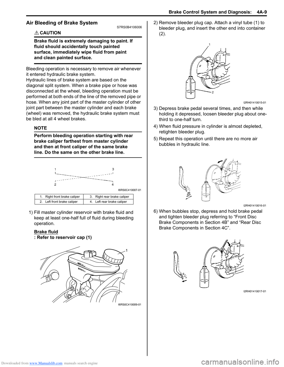
Perform bleeding operation starting with rear
brake caliper farthest from master cylinder
and then at front caliper of the same brake
line. Do the same on the other brake line.
1) Fill master cylinder rese rvoir with brake fluid and
keep at least one-half full of fluid during bleeding
operation.
Brake fluid
: Refer to reservoir cap (1) 2) Remove bleeder plug cap. Attach a vinyl tube (1) to
bleeder plug, and insert the other end into container
(2).
3) Depress brake pedal several times, and then while holding it depressed, loosen bleeder plug about one-
third to one-half turn.
4) When fluid pressure in cy linder is almost depleted,
retighten bleeder plug.
5) Repeat this operation until there are no more air bubbles in hydraulic line.
6) When bubbles stop, depress and hold brake pedal and tighten bleeder plug referring to “Front Disc
Brake Components in Section 4B” and “Rear Disc
Brake Components in Section 4C”.
1. Right front brake caliper 3. Right rear brake caliper
2. Left front brake caliper 4. Left rear brake caliper
I6RS0C410007-01
1
I6RS0C410009-01
I2RH01410015-01
I2RH01410016-01
I2RH01410017-01