2007 SUZUKI SWIFT Air bag replacement
[x] Cancel search: Air bag replacementPage 6 of 1496
Downloaded from www.Manualslib.com manuals search engine 00-1 Precautions:
Precautions
Precautions
Precautions
Precautions for Vehicles Equipped with a
Supplemental Restraint (Air Bag) System
S7RS0B0000001
WARNING!
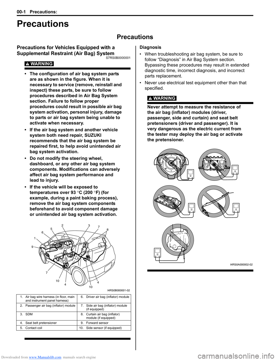
• The configuration of air bag system parts are as shown in the figure. When it is
necessary to service (remove, reinstall and
inspect) these parts, be sure to follow
procedures described in Air Bag System
section. Failure to follow proper
procedures could result in possible air bag
system activation, personal injury, damage
to parts or air bag system being unable to
activate when necessary.
• If the air bag system and another vehicle system both need repair, SUZUKI
recommends that the air bag system be
repaired first, to help avoid unintended air
bag system activation.
• Do not modify the steering wheel, dashboard, or any other air bag system
components. Modifications can adversely
affect air bag system performance and
lead to injury.
• If the vehicle will be exposed to temperatures over 93 °C (200 °F) (for
example, during a paint baking process),
remove the air bag system components
beforehand to avoid component damage
or unintended air bag system activation.
Diagnosis
• When troubleshooting air bag system, be sure to follow “Diagnosis” in Air Bag System section.
Bypassing these procedures may result in extended
diagnostic time, incorrect diagnosis, and incorrect
parts replacement.
• Never use electrical test equipment other than that specified.
WARNING!
Never attempt to measure the resistance of
the air bag (inflator) modules (driver,
passenger, side and curtain) and seat belt
pretensioners (driver and passenger). It is
very dangerous as the electric current from
the tester may deploy the air bag or activate
the pretensioner.
1. Air bag wire harness (in floor, main and instrument panel harness) 6. Driver air bag (inflator) module
2. Passenger air bag (inflator) module 7. Side air bag (inflator) module (if equipped)
3. SDM 8. Curtain air bag (inflator) module (if equipped)
4. Seat belt pretensioner 9. Forward sensor
5. Contact coil 10. Side sensor (if equipped)
1 2
3
4
4
5
6
7 7
8
9
10 10
I4RS0B000001-02
I4RS0A000002-02
Page 15 of 1496
Downloaded from www.Manualslib.com manuals search engine Precautions: 00-10
Air Bag WarningS7RS0B0000009
WARNING!
For vehicles equipped with Supplemental
Restraint (Air Bag) System:
• Service on and around the air bag system components or wiring must be performed
only by an authorized SUZUKI dealer. Refer
to “Air Bag System Components, Wiring
and Connectors Location in Section 8B” in
order to confirm whether you are
performing service on or near the air bag
system components or wiring. Please
observe all WARNINGS in Air Bag System
section and “Precautions on Service and
Diagnosis of Air Bag System in Section
8B” before performing service on or
around the air bag system components or
wiring. Failure to follow WARNINGS could
result in unintentional activation of the
system or could render the system
inoperative. Either of these two conditions
may result in severe injury.
• Technical service work must be started at least 90 seconds after the ignition switch is
turned to the LOCK position and the
negative cable is disconnected from the
battery. Otherwise, the system may be
activated by reserve energy in the Sensing
and Diagnostic Module (SDM).
Air Bag System Service WarningS7RS0B0000010
WARNING!
• Service on or around the air bag system components or wiring must be performed
only by an authorized SUZUKI dealer.
Please observe all WARNINGS in Air Bag
System section and “Precautions on
Service and Diagnosis of Air Bag System
in Section 8B” before performing service
on or around the air bag system
components or wiring. Failure to follow
WARNINGS could result in unintended
activation of the system or could render
the system inoperative. Either of these two
conditions may result in severe injury.
• The procedures in the air bag system section must be followed in the order
listed to disable the air bag system
temporarily and prevent false DTCs from
setting. Failure to follow procedures could
result in possible activation of the air bag
system, personal injury or otherwise
unneeded air bag system repairs.
Fastener CautionS7RS0B0000011
CAUTION!
When fasteners are removed, always reinstall
them at the same location from which they
were removed. If a fastener needs to be
replaced, use the correct part number
fastener for that application. If the correct
part number fastener is not available, a
fastener of equal size and strength (or
stronger) may be used. Fasteners that are not
reused, and those requiring thread-locking
compound, will be called out. The correct
torque value must be used when installing
fasteners that require it. If the conditions are
not followed, parts or system damage could
result.
Suspension CautionS7RS0B0000012
CAUTION!
• All suspension fasteners are an important attaching part in that it could affect the
performance of vital parts and systems,
and/or could result in major repair
expense. They must be replaced with one
of the same part number or with an
equivalent part if replacement becomes
necessary. Do not use a replacement part
of lesser quality or substitute design.
Torque values must be used as specified
during reassembly to assure proper
retention of this part.
• Never attempt to heat, quench or straighten any suspension part. Replace it
with a new part or damage to the part may
result.
Wheels and Tires CautionS7RS0B0000013
CAUTION!
All wheel fasteners are important attaching
parts in that they could affect the
performance of vital parts and systems, and/
or could result in major repair expense. They
must be replaced with one of the same part
number or with an eq uivalent part if
replacement becomes necessary. Do not use
a replacement part of lesser quality or
substitute design. Torque values must be
used as specified during reassembly to
assure proper retention of all parts.
There is to be no welding as it may result in
extensive damage and weakening of the
metal.
Page 746 of 1496
Downloaded from www.Manualslib.com manuals search engine 5A-102 Automatic Transmission/Transaxle:
Operation Check
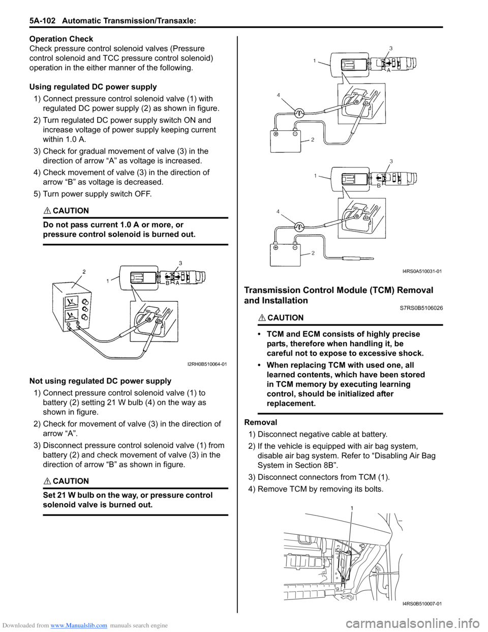
Check pressure control solenoid valves (Pressure
control solenoid and TCC pressure control solenoid)
operation in the either manner of the following.
Using regulated DC power supply
1) Connect pressure contro l solenoid valve (1) with
regulated DC power supply (2) as shown in figure.
2) Turn regulated DC power supply switch ON and increase voltage of power supply keeping current
within 1.0 A.
3) Check for gradual movement of valve (3) in the direction of arrow “A” as voltage is increased.
4) Check movement of valve (3) in the direction of arrow “B” as voltage is decreased.
5) Turn power supply switch OFF.
CAUTION!
Do not pass current 1.0 A or more, or
pressure control solenoid is burned out.
Not using regulated DC power supply 1) Connect pressure control solenoid valve (1) to battery (2) setting 21 W bulb (4) on the way as
shown in figure.
2) Check for movement of valve (3) in the direction of arrow “A”.
3) Disconnect pressure control solenoid valve (1) from battery (2) and check movement of valve (3) in the
direction of arrow “B” as shown in figure.
CAUTION!
Set 21 W bulb on the way, or pressure control
solenoid valve is burned out.
Transmission Control Module (TCM) Removal
and Installation
S7RS0B5106026
CAUTION!
• TCM and ECM consists of highly precise
parts, therefore when handling it, be
careful not to expose to excessive shock.
• When replacing TCM with used one, all learned contents, which have been stored
in TCM memory by executing learning
control, should be initialized after
replacement.
Removal
1) Disconnect negative cable at battery.
2) If the vehicle is equipped with air bag system, disable air bag system. Refer to “Disabling Air Bag
System in Section 8B”.
3) Disconnect connectors from TCM (1).
4) Remove TCM by removing its bolts.
I2RH0B510064-01
I4RS0A510031-01
1
I4RS0B510007-01
Page 747 of 1496
Downloaded from www.Manualslib.com manuals search engine Automatic Transmission/Transaxle: 5A-103
Installation
Reverse removal procedure noting the following.
• Connect TCM connectors securely.
• If the vehicle is equipped with air bag system, be sure to enable air bag system after TCM is back in place.
Refer to “Enabling Air Bag System in Section 8B”.
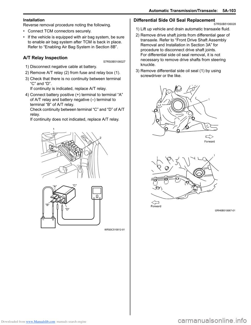
A/T Relay InspectionS7RS0B5106027
1) Disconnect negative cable at battery.
2) Remove A/T relay (2) from fuse and relay box (1).
3) Check that there is no continuity between terminal “C” and “D”.
If continuity is indicated, replace A/T relay.
4) Connect battery positive (+ ) terminal to terminal “A”
of A/T relay and battery negative (–) terminal to
terminal “B” of A/T relay.
Check continuity between terminal “C” and “D” of A/T
relay.
If continuity does not indicated, replace A/T relay.
Differential Side Oil Seal ReplacementS7RS0B5106028
1) Lift up vehicle and drain automatic transaxle fluid.
2) Remove drive shaft joints from differential gear of transaxle. Refer to “Front Drive Shaft Assembly
Removal and Installation in Section 3A” for
procedure to disconnect drive shaft joints.
For differential side oil seal removal, it is not
necessary to remove drive shafts from steering
knuckle.
3) Remove differential side oil seal (1) by using screwdriver or the like.
"D"
"B" "A"
"C"
1
2
I6RS0C510012-01
I2RH0B510067-01
Page 1039 of 1496
Downloaded from www.Manualslib.com manuals search engine Air Bag System: 8B-1
Restraint
Air Bag System
Precautions
Precautions on Service and Diagnosis of Air
Bag System
S7RS0B8200001
WARNING!
• If the air bag system and another vehicle system both need repair, SUZUKI
recommends that the air bag system be
repaired first, to help avoid unintended air
bag system activation.
• Do not modify the steering wheel, dashboard, both front seat or any other on
or around air bag system components.
Modifications can adversely affect air bag
system performance and lead to injury.
• Be sure to follow the procedures described in this section. Failure to follow
procedures could result in possible air bag
system activation, personal injury or
unneeded air bag system repairs.
• WARNING / CAUTION labels are attached on each
part of air bag system components (SDM, air bag
(inflator) modules and seat belt pretensioners). Be
sure to follow the instructions.
• Many of service procedures require disconnection of
“A/BAG” fuse and air bag (inflator) module(s) (driver,
passenger, side of both si des and curtain of both
sides) from initiator circuit to avoid an accidental
deployment.
• Do not apply power to the air bag system unless all components are connected or a diagnostic flow
requests it, as this will set a DTC.
• The “Air Bag Diagnostic S ystem Check” must be the
starting point of any air bag diagnostics. The “Air Bag
Diagnostic System Check” will verify proper “AIR
BAG” warning right operatio n and will lead you to the
correct flow to diagnose any air bag malfunctions.
Bypassing these procedures may result in extended
diagnostic time, incorrect diagnosis, and incorrect
parts replacements. • Never use air bag component parts from another
vehicle.
• If the vehicle will be exposed to temperatures over 93
° C (200 °F) (for example, during a paint baking
process), remove the air bag system components
beforehand to avoid component damage or
unintended system activation.
• When handling the air bag (inflator) modules (driver, passenger, side of both si des and curtain of both
sides), seat belt pretensio ners (driver and passenger),
SDM, forward-sensor or side-sensor, be careful not to
drop it or apply an impact to it. If an excessive impact
was applied (e.g., SDM, forward-sensor and side-
sensor are dropped, air bag (inflator) module is
dropped from a height of 90 cm (3 ft) or more, seat
belt pretensioner (retractor assembly) is dropped from
a height of 30 cm (1 ft) or more), never attempt
disassembly or repair but replace it with a new one.
• When using electric welding, be sure to disconnect air bag (inflator) module connectors (driver, passenger,
side of both sides and curtain of both sides) and seat
belt pretensioner connectors (driver and passenger)
respectively.
• When applying paint around the air bag system related parts, use care so that the harness or
connector will not be expo sed to the paint mist.
• Never expose air bag system component parts directly to hot air (drying or baking the vehicle after
painting) or flames.
WARNING!
When performing service on or around air
bag system components or air bag wiring,
follow the procedures listed in “Disabling Air
Bag System” to temporarily disable the air
bag system.
Failure to follow procedures could result in
possible air bag system activation, personal
injury or unneeded air bag system repairs.
Page 1048 of 1496
Downloaded from www.Manualslib.com manuals search engine 8B-10 Air Bag System:
Diagnostic Information and Procedures
Air Bag Diagnostic System CheckS7RS0B8204001
WARNING!
To avoid deployment when troubleshooting
the air bag system, do not use electrical test
equipment such as a battery powered or AC
powered voltmeter, ohmmeter, etc., or any
type of electrical equipment other than that
specified in this manual. Do not use a non-
powered probe type tester.
Instructions in this manual must be followed
carefully, otherwise personal injury may
result.
CAUTION!
The order in which DTCs are diagnosed is
very important. Failure to diagnose the DTCs
in the order specified may result in extended
diagnostic time, incorrect diagnosis and
incorrect parts replacement.
The diagnostic procedures used are designed to find
and repair air bag system malfunctions.
To get the best results, it is important to use the
diagnostic flow and follow the sequence in the following.1) Perform the “Air Bag Diagnostic System Check Flow”.
(The “Air Bag Diagnostic System Check Flow” must
be the starting point of any air bag system diagnosis.
The “Air Bag Diagnostic System Check Flow” checks
for proper “AIR BAG” warning right operation
through “AIR BAG” warning right and whether air
bag DTCs exist.)
2) Refer to the proper diagnost ic flow as directed by the
“Air Bag Diagnostic System Check Flow”.
(The “Air Bag Diagnostic System Check Flow” will
lead you to the correct flow to diagnose any air bag
system malfunctions. Bypassing these procedures
may result in extended diagnostic time, incorrect
diagnosis and incorrect parts replacement.)
3) Repeat the “Air Bag Diagnostic System Check Flow” after any repair or diagnostic procedures have been
performed.
(Performing the “Air Bag Diagnostic System Check
Flow” after all repair or diagnostic procedures will
ensure that the repair has been made correctly and
that no other malfunctions exist.)
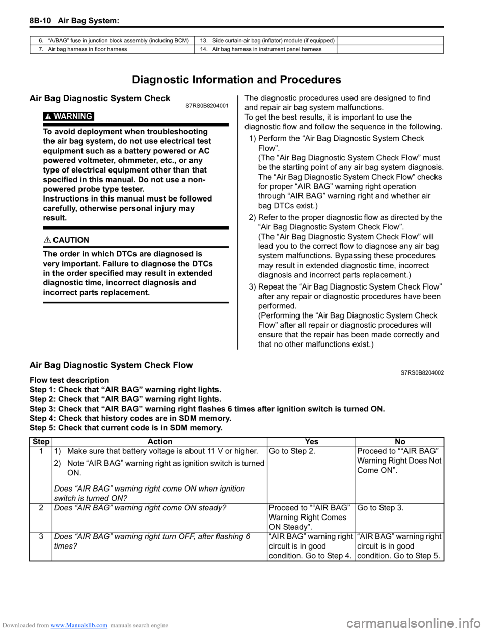
Air Bag Diagnostic System Check FlowS7RS0B8204002
Flow test description
Step 1: Check that “AIR BAG” warning right lights.
Step 2: Check that “AIR BAG” warning right lights.
Step 3: Check that “AIR BAG” warning right flas hes 6 times after ignition switch is turned ON.
Step 4: Check that history codes are in SDM memory.
Step 5: Check that current code is in SDM memory.
6. “A/BAG” fuse in junction block assembly (including BCM) 13. Side curtain-air bag (inflator) module (if equipped)
7. Air bag harness in floor harness 14. Air bag harness in instrument panel harness
Step Action YesNo
1 1) Make sure that battery voltage is about 11 V or higher.
2) Note “AIR BAG” warning right as ignition switch is turned
ON.
Does “AIR BAG” warning ri ght come ON when ignition
switch is turned ON? Go to Step 2.
Proceed to ““AIR BAG”
Warning Right Does Not
Come ON”.
2 Does “AIR BAG” warning right come ON steady? Proceed to ““AIR BAG”
Warning Right Comes
ON Steady”.Go to Step 3.
3 Does “AIR BAG” warning right turn OFF, after flashing 6
times? “AIR BAG” warning right
circuit is in good
condition. Go to Step 4.“AIR BAG” warning right
circuit is in good
condition. Go to Step 5.
Page 1134 of 1496
Downloaded from www.Manualslib.com manuals search engine 8B-96 Air Bag System:
Repair and Inspection Required after AccidentS7RS0B8204049
CAUTION!
• All air bag system components, including the electrical harness (component
mounting points), must be inspected after
an accident. If any components are
damaged or bent, they must be replaced
even if air bag system activation did not
occur.
• Never use air bag system parts from another vehicle.
• Do not attempt to service the parts below. Service of these parts is by replacement
only.
– Driver / Passenger air bag (inflator) modules
– Driver / Passenger side-air bag (inflator) modules
– Driver / Passenger side curtain-air bag (inflator) modules
– Driver / Passenger seat belt pretensioners
–Forward-sensor
– Driver / Passenger side-sensors
–SDM
– Contact coil and combination switch assembly
– Air bag wire harness in main harness, instrument panel harness and floor
harness.
• Proper operation of the sensors and air bag system requires that any repairs to the
vehicle structure return it to its original
production configuration.
CAUTION!
After detecting one time of such collision as
to meet deployment conditions, the SDM
must not be used.
Refer to “Air Bag Diagnostic System Check”
when checking the SDM.
Accident with Deployment / Activation – Component
Replacement
When driver and passenger air bags are deployed, the
following components must be replaced.
• Driver and passenger air bag (inflator) modules
• Driver and passenger seat belt pretensioners
• SDM after detecting such collision as to meet
deployment conditions
• Forward-sensor
• Instrument panel When side-air bag and side curtain-air bag are deployed,
the following components must be replaced.
• Deployed side-air bag (inflator) module
• Deployed side curtain-air bag (inflator) module
• Side-sensor
•SDM
Accident with or without Deployment / Activation –
Component Inspections
Certain air bag and restraint system components must
be inspected after any crash, whether the air bag system
activated or not. If any faul
ty condition is found in the
following checks, replace faulty part.
Those components are:
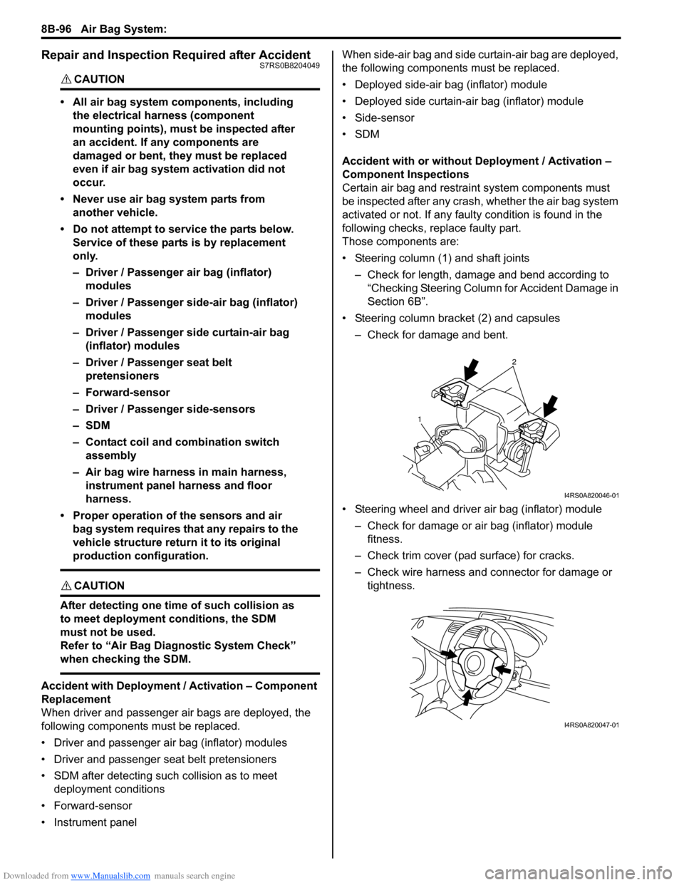
• Steering column (1) and shaft joints
– Check for length, damage and bend according to “Checking Steering Column for Accident Damage in
Section 6B”.
• Steering column bracket (2) and capsules – Check for damage and bent.
• Steering wheel and driver air bag (inflator) module – Check for damage or air bag (inflator) module fitness.
– Check trim cover (pad surface) for cracks.
– Check wire harness and connector for damage or tightness.
2
1
I4RS0A820046-01
I4RS0A820047-01
Page 1135 of 1496
Downloaded from www.Manualslib.com manuals search engine Air Bag System: 8B-97
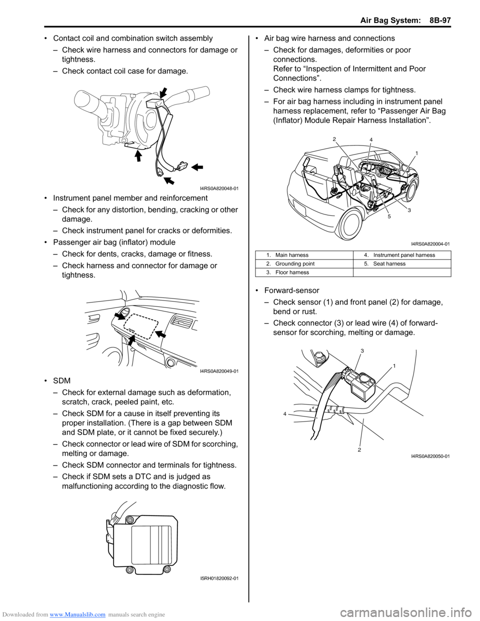
• Contact coil and combination switch assembly
– Check wire harness and connectors for damage or tightness.
– Check contact coil case for damage.
• Instrument panel member and reinforcement – Check for any distortion, bending, cracking or other damage.
– Check instrument panel fo r cracks or deformities.
• Passenger air bag (inflator) module
– Check for dents, cracks, damage or fitness.
– Check harness and connector for damage or tightness.
•SDM – Check for external damage such as deformation, scratch, crack, peeled paint, etc.
– Check SDM for a cause in itself preventing its proper installation. (There is a gap between SDM
and SDM plate, or it cannot be fixed securely.)
– Check connector or lead wire of SDM for scorching, melting or damage.
– Check SDM connector and terminals for tightness.
– Check if SDM sets a DTC and is judged as malfunctioning according to the diagnostic flow. • Air bag wire harness and connections
– Check for damages, deformities or poor connections.
Refer to “Inspection of Intermittent and Poor
Connections”.
– Check wire harness clamps for tightness.
– For air bag harness including in instrument panel harness replacement, refer to “Passenger Air Bag
(Inflator) Module Repair Harness Installation”.
• Forward-sensor – Check sensor (1) and front panel (2) for damage, bend or rust.
– Check connector (3) or lead wire (4) of forward- sensor for scorching, melting or damage.
I4RS0A820048-01
I4RS0A820049-01
I5RH01820092-01
1. Main harness 4. Instrument panel harness
2. Grounding point 5. Seat harness
3. Floor harness
1
2
3
4
5
I4RS0A820004-01
1
3
2
4
I4RS0A820050-01