Page 848 of 1496

Downloaded from www.Manualslib.com manuals search engine 5B-34 Manual Transmission/Transaxle:
Assembly
Judging from abnormality noted before disassembly and
what is found through visual check of component parts
after disassembly, prepare replacing parts and proceed
to reassembly. Make sure that all parts are clean.
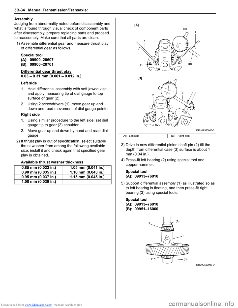
1) Assemble differential gear and measure thrust play
of differential gear as follows.
Special tool
(A): 09900–20607
(B): 09900–20701
Differential gear thrust play
0.03 – 0.31 mm (0.001 – 0.012 in.)
Left side
1. Hold differential assembly with soft jawed vise and apply measuring tip of dial gauge to top
surface of gear (2).
2. Using 2 screwdrivers (1), move gear up and down and read movement of dial gauge pointer.
Right side
1. Using similar procedure to the left side, set dial gauge tip to gear (2) shoulder.
2. Move gear up and down by hand and read dial gauge.
2) If thrust play is out of sp ecification, select suitable
thrust washer from among the following available
size, install it and check again that specified gear
play is obtained.
Available thrust washer thickness
3) Drive in new differential pinion shaft pin (2) till the depth from differential case (3) surface is about 1
mm (0.04 in.).
4) Press-fit left bearing (2) using special tool and copper hammer.
Special tool
(A): 09913–76010
5) Support differential assembly (1) as illustrated so as to left bearing is floating , and then press-fit right
bearing (3) using special tools.
Special tool
(A): 09913–76010
(B): 09951–16060
0.85 mm (0.033 in.) 1.05 mm (0.041 in.)
0.90 mm (0.035 in.) 1.10 mm (0.043 in.)
0.95 mm (0.037 in.) 1.15 mm (0.045 in.)
1.00 mm (0.039 in.)
[A]: Left side
[B]: Right side
I3RH0A520083-01
1
(A)
3
2 (B)
I6RS0C520008-01
Page 849 of 1496

Downloaded from www.Manualslib.com manuals search engine Manual Transmission/Transaxle: 5B-35
6) Hold differential assembly with soft jawed vise (3),
install final gear (2) as shown in figure and then
tighten bolts (1) to specified torque.
CAUTION!
Use of any other bolts than specified ones is
prohibited.
Tightening torque
Final gear bolt (a): 90 N·m (9.0 kgf-m, 65.0 lb-ft)
Specifications
Tightening Torque SpecificationsS7RS0B5207001
NOTE
The specified tightening torque is also described in the following.
“Gear Shift Control Leve r and Cable Components”
“Manual Transaxle Unit Components”
“Gear Shift and Select Shaft Assembly Components”
“Manual Transaxle Assembly Components”
“Gear Shift Shaft Components”
“Differential Components”
Reference:
For the tightening torque of fastener not specified in this section, refer to “Fasteners Information in Section 0A”.
I4RS0A520043-01
Fastening part Tightening torque
Note
N ⋅mkgf-mlb-ft
Transaxle oil drain plug 21 2.1 15.5 �)
Transaxle oil level / filler plug 21 2.1 15.5 �)
Back up light switch 23 2.3 17.0 �)
Gear shift guide case bolt 23 2.3 17.0 �)
Select lever bracket bolt 23 2.3 17.0 �)
Gear shift interlock bolt 23 2.3 17.0 �)
5th to reverse interlock guide bolt 23 2.3 17.0 �)
Countershaft nut 100 10.0 72.5 �)
Shift fork bolt 10 1.0 7.5 �)
Side cover bolt 10 1.0 7.5 �)
Reverse gear shift lever bolt 23 2.3 17.0 �)
Reverse shaft bolt 23 2.3 17.0 �)
Transaxle case bolt 23 2.3 17.0 �)
Side bearing retainer bolt 23 2.3 17.0 �)
Gear shift locating bolt 13 1.3 9.5 �)
Left case plate bolt 23 2.3 17.0 �)
Oil gutter bolt 10 1.0 7.5 �)
Final gear bolt 90 9.0 65.0 �)
Page 1467 of 1496

Downloaded from www.Manualslib.com manuals search engine Keyless Start System: 10E-5
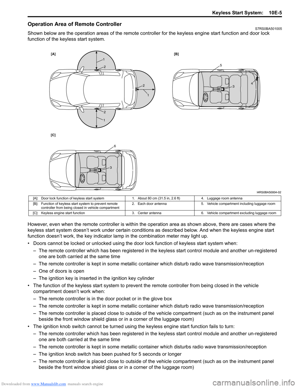
Operation Area of Remote ControllerS7RS0BA501005
Shown below are the operation areas of the remote controller for the keyless engine start function and door lock
function of the keyless start system.
However, even when the remote controller is within the operation area as shown above, there are cases where the
keyless start system doesn’t work under certain conditi ons as described below. And when the keyless engine start
function doesn’t work, the key indicator la mp in the combination meter may light up.
• Doors cannot be locked or unlocked using the doo r lock function of keyless start system when:
– The remote controller which has been registered in the keyless start control module and another un-registered one are both carried at the same time
– The remote controller is kept in some metallic co ntainer which disturb radio wave transmission/reception
– One of doors is open
– The ignition key is inserted in the ignition key cylinder
• The function of the keyless start system to prevent the remote controller from being closed in the vehicle
compartment doesn’t work when:
– The remote controller is in the door pocket or in the glove box
– The remote controller is kept in some metallic co ntainer which disturb radio wave transmission/reception
– The remote controller is placed close to outside of the vehicle compartment (such as on the instrument panel beside the front window shield glass or in a corner of the luggage room)
• The ignition knob switch cannot be turned usin g the keyless engine start function fails to turn:
– The remote controller which has been registered in the keyless start control module and another un-registered one are both carried at the same time
– The remote controller is kept in some metallic cont ainer which disturbs radio wave transmission/reception
– The ignition knob switch has been pushed for 5 seconds or longer
– The remote controller is placed close to outside of the vehicle compartment (such as on the instrument panel beside the front window shield glass or in a corner of the luggage room)
[A] [B]
[C]
1
1
1
25
6
3
3 4
2
2
I4RS0BA50004-02
[A]: Door lock function of keyless start system 1. About 80 cm (31.5 in, 2.6 ft)4. Luggage room antenna
[B]: Function of keyless start system to prevent remote controller from being closed in vehicle compartment 2. Each door antenna
5. Vehicle compartment including luggage room
[C]: Keyless engine start function 3. Center antenna6. Vehicle compartment excluding luggage room