Page 1058 of 1496

Downloaded from www.Manualslib.com manuals search engine 8B-20 Air Bag System:
DTC B1017: Power Source Voltage LowS7RS0B8204013
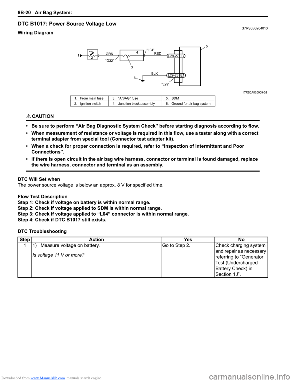
Wiring Diagram
CAUTION!
• Be sure to perform “Air Bag Diagnostic System Check” before starting diagnosis according to flow.
• When measurement of resistance or voltage is required in this flow, use a tester along with a correct terminal adapter from special tool (Connector test adapter kit).
• When a check for proper connection is required, refer to “Inspection of Intermittent and Poor Connections”.
• If there is open circuit in the air bag wire harnes s, connector or terminal is found damaged, replace
the wire harness, connector and terminal as an assembly.
DTC Will Set when
The power source voltage is below an approx. 8 V for specified time.
Flow Test Description
Step 1: Check if voltage on ba ttery is within normal range.
Step 2: Check if voltage applie d to SDM is within normal range.
Step 3: Check if voltage applied to “L04” connector is within normal range.
Step 4: Check if DTC B1017 still exists.
DTC Troubleshooting
1 2
3
GRN
RED
6
BLK
L29-27
L29-28 IG
E1 5
4
“L29”
“L04”
“G32”
I7RS0A820009-02
1. From main fuse 3. “A/BAG” fuse 5. SDM
2. Ignition switch 4. Junction block assembly 6. Ground for air bag system
Step Action YesNo
1 1) Measure voltage on battery.
Is voltage 11 V or more? Go to Step 2.
Check charging system
and repair as necessary
referring to “Generator
Test (Undercharged
Battery Check) in
Section 1J”.
Page 1059 of 1496

Downloaded from www.Manualslib.com manuals search engine Air Bag System: 8B-21
NOTE
Upon completion of inspection and repair work, perform the following items.
• Reconnect all air bag system components and ensure all components are properly mounted.
• Clear DTCs referring to “DTC Clearance”, if any.
• Repeat “Air Bag Diagnostic System Check” to confirm that the trouble has been corrected.
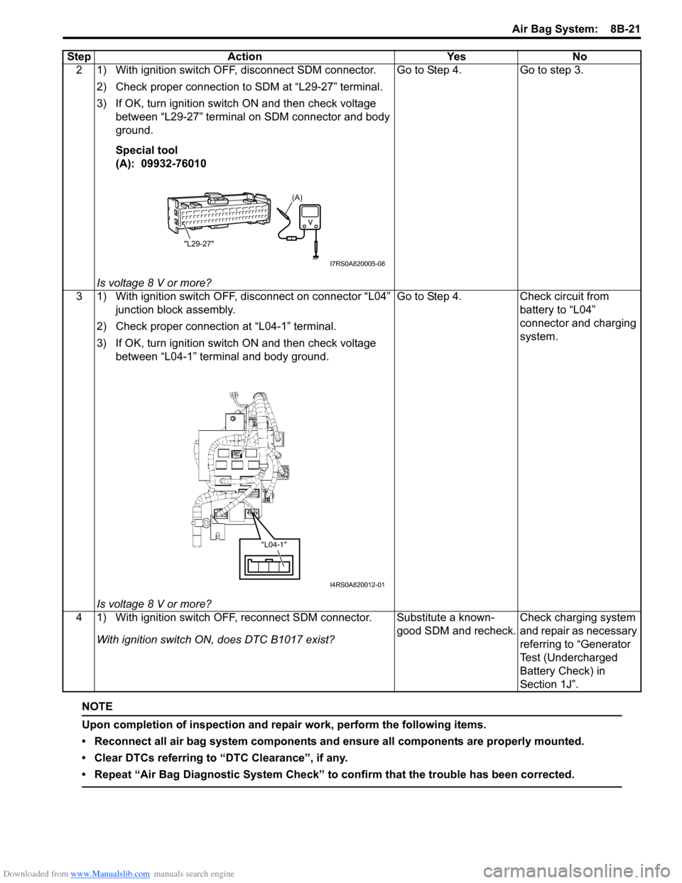
2 1) With ignition switch OFF, disconnect SDM connector.2) Check proper connection to SDM at “L29-27” terminal.
3) If OK, turn ignition switch ON and then check voltage between “L29-27” terminal on SDM connector and body
ground.
Special tool
(A): 09932-76010
Is voltage 8 V or more? Go to Step 4. Go to step 3.
3 1) With ignition switch OFF, disconnect on connector “L04” junction block assembly.
2) Check proper connection at “L04-1” terminal.
3) If OK, turn ignition switch ON and then check voltage between “L04-1” terminal and body ground.
Is voltage 8 V or more? Go to Step 4. Check circuit from
battery to “L04”
connector and charging
system.
4 1) With ignition switch OFF, reconnect SDM connector. With ignition switch ON, does DTC B1017 exist? Substitute a known-
good SDM and recheck.
Check charging system
and repair as necessary
referring to “Generator
Test (Undercharged
Battery Check) in
Section 1J”.
Step Action Yes No
(A)
"L29-27"
I7RS0A820005-08
"L04-1"
I4RS0A820012-01
Page 1182 of 1496

Downloaded from www.Manualslib.com manuals search engine 9A-11 Wiring Systems:
C: Engine harnessNo./Color Connective position No./Color Connective positionC01/GRY IAC valve C22/- Generator #2
C02/GRY IG Coil #1 C23/BLK Starting motor #1
C03/GRY IG Coil #2 C24/- Starting motor #2
C04/GRY Fuel injector #1 C25/GR Y VSS (Vehicle speed sensor)
C05/GRY Fuel injector #2 C26/GRY Knock sensor
C06/GRY Fuel injector #3 C27/BLU (A/
T) Input shaft speed sensor
C07/GRY Fuel injector #4 C28/GRY
(A/T) Trans axle range sensor
C08/BLK or GRY CMP sensor C29/GRY
(A/T) Shift solenoid
C09/BLK ECT sensor C30/BLK
(M/T) Back-up light switch
C10/GRY EGR stepper motor C31/- Main fuse box C11/BLK Throttle position sensor C32/GRY
(IF EQPD) Current sensor
C12/BLK MAP sensor C33/- Main fuse box
C13/BLK MAF sensor C34/N (A/T) TCM
C14/BLK EVAP canister purge valve C35/N (A/T) TCM
C15/GRY Heated oxygen sensor #1 C36/N Main harness (To E24)
C16/GRN Heated oxygen sensor #2 C37/GRY ECM C17/BLK A/C compressor C38/- Weld splice C18/N Oil pressure switch C39/- Weld splice
C19/BLU VVT solenoid C40/- Weld splice
C20/GRY CKP sensor C41/- Weld splice
C21/GRY or BLK Generator #1
Page 1184 of 1496

Downloaded from www.Manualslib.com manuals search engine 9A-13 Wiring Systems:
C: Engine harness
D: Oil pressure switch wireNo./Color Connective position No./Color Connective position
C02/GRY IG Coil #1 C24/- Starting motor #2
C03/GRY IG Coil #2 C23/BLK Starting motor #1
C04/GRY Fuel injector #1 C25/GRY
(A/T) VSS (Vehicle speed sensor)
C05/GRY Fuel injector #2 C26/GRY Knock shaft speed sensor
C06/GRY Fuel injector #3 C27/BLU (A/
T) Input shaft speed sensor
C07/GRY Fuel injector #4 C28/GRY
(A/T) Trans axle range sensor
C08/BLK CMP sensor C29/GRY
(A/T) Shift solenoid
C09/BLK ECT sensor C30/BLK
(M/T) Back-up light switch
C10/GRY EGR stepper motor C31/- Main fuse box C12/BLK MAP sensor C32/GRY Current sensor
C13/BLK MAF sensor C33/- Main fuse box
C14/BLK EVAP canister purge valve C34/N (A/T) TCM
C15/BLK Heated oxygen sensor #1 C35/N (A/T) TCM
C16/GRN Heated oxygen sensor #2 C36/N Main harness (To E24) C17/BLK A/C compressor C37/GRY ECM C18/N Oil pressure switch wire (To D02) C38/- Weld splice
C19/BLU VVT solenoid C39/- Weld splice
C20/GRY CKP sensor C40/- Weld splice C21/BLK Generator #1 C42/BLK Electric throttle body C22/- Generator #2
No./Color Connective position No./ColorConnective position
D01/N Oil pressure switch D02/GRY Engine harness (To C18)
Page 1203 of 1496
Downloaded from www.Manualslib.com manuals search engine Wiring Systems: 9A-32
G32
J/B
3
WHT/BLU
4G213
12
10
BLK
21
BLK/GRY
10A
15A30A
5647891012
E27
WHT
131416192021
BLUBLU/YEL
6
BLK/YEL
5
YEL/BLU
7
PNK
89
WHT/RED
RED
GRN
12
WHT
GRY
14
WHT/GRN
19
WHT/BLU
2021
WHT/REDWHT/BLU
16
15A
15A 30A 50A
30A
30A 30A
30A
15A15A
15A
BLK
2E261
WHT/BLU
C31 C331 1
WHT
BLK
Main fuse box
Starting motor "A-1"
Generator
"A-2"
Battery
80A
50A
50A
3
80A
47
80A
46
2
1
E401WHT
"Junction Block
Inner circuit"
J/B (E40- )
YEL
"Junction BlockInner circuit"
J/B (G32- )
2
1
"Junction BlockInner circuit"
J/B (E39- ) 7
J/B (G32- ) 4
GRN/WHT
Individual circuit fuse box
+B1
LOCK
ACC
ON
ST ACC IG1 IG2
STOUT
IN
+B2
6
GRN
J/B (G32- )
2
5BLU
J/B (G32- )5
IF EQPD
18
YEL/BLU
18
15A
M16A engine
W
B
RHD
LHDAB
A
A
B1 2AB21
B
I6RS0C910907-01
Page 1204 of 1496
Downloaded from www.Manualslib.com manuals search engine 9A-33 Wiring Systems:
Fuses and the Protected PartsS7RS0B910D002
The chart below describes what parts each fuse protects.
Fuses in Main Fuse Box (RHD)S7RS0B910D003
Fuses in Main Fuse Box (LHD)S7RS0B910D004
No.Fuse Protected circuit
80 A All electric circuit
Battery
Generator
50 A LAMP
50 A IG switch
Supplementary fuse box No.2 (In J/B)
80 A Individual circuit fuse box
80 A Individual circuit fuse box
1
3
2
I4RS0A910905-01
2
3
47
46
1
I4RS0B910974-01
Page 1206 of 1496

Downloaded from www.Manualslib.com manuals search engine 9A-35 Wiring Systems:
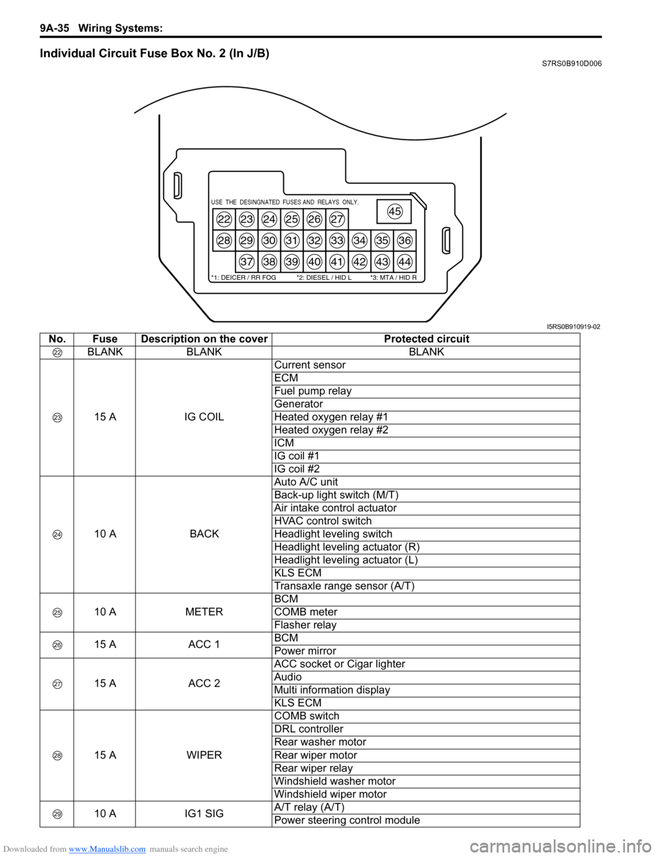
Individual Circuit Fuse Box No. 2 (In J/B)S7RS0B910D006
22
28
23
29
37
24
30
38
25
31
39
26
32
40
27
33
41
34
42
35
43
36
44
45USE THE DESINGNATED FUSES AND RELAYS ONLY.
*1: DEICER / RR FOG *2: DIESEL / HID L *3: MTA / HID R
I5RS0B910919-02
No. Fuse Description on the coverProtected circuit
BLANK BLANK BLANK
15 A IG COILCurrent sensor
ECM
Fuel pump relay
Generator
Heated oxygen relay #1
Heated oxygen relay #2
ICM
IG coil #1
IG coil #2
10 A BACKAuto A/C unit
Back-up light switch (M/T)
Air intake control actuator
HVAC control switch
Headlight leveling switch
Headlight leveling actuator (R)
Headlight leveling actuator (L)
KLS ECM
Transaxle range sensor (A/T)
10 A METERBCM
COMB meter
Flasher relay
15 A ACC 1BCM
Power mirror
15 A ACC 2ACC socket or Cigar lighter
Audio
Multi information display
KLS ECM
15 A WIPERCOMB switch
DRL controller
Rear washer motor
Rear wiper motor
Rear wiper relay
Windshield washer motor
Windshield wiper motor
10 A IG1 SIGA/T relay (A/T)
Power steering control module
Page 1218 of 1496
Downloaded from www.Manualslib.com manuals search engine 9A-47 Wiring Systems:
A-2 Charging System Circuit DiagramS7RS0B910E003
4E24
C36
BLK/WHT
BLK/WHT
BLK/WHT
80A
Main fuse box
C22
J/B
1C33
IG COIL1
15A
23
GeneratorIC
regulator
1
E415
C212
4
WHT/BLU
WB
BCM
"A-8"
1
BLU/YEL
BY
3
BRN/WHT
BW
ECM
"A-5"
16
WHT/BLU
BLK
Weld splice
C39
IF EQPD
I7RS0B910910-01