2007 SUZUKI SWIFT brake disc
[x] Cancel search: brake discPage 539 of 1496
Downloaded from www.Manualslib.com manuals search engine Parking Brake: 4D-4
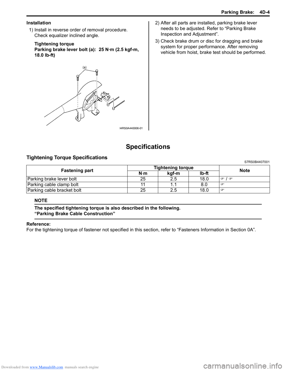
Installation1) Install in reverse order of removal procedure. Check equalizer inclined angle.
Tightening torque
Parking brake lever bolt (a): 25 N·m (2.5 kgf-m,
18.0 lb-ft) 2) After all parts are installed, parking brake lever
needs to be adjusted. Refer to “Parking Brake
Inspection and Adjustment”.
3) Check brake drum or disc for dragging and brake system for proper performance. After removing
vehicle from hoist, brake test should be performed.
Specifications
Tightening Torque SpecificationsS7RS0B4407001
NOTE
The specified tightening torque is also described in the following.
“Parking Brake Cable Construction”
Reference:
For the tightening torque of fastener not specified in this section, refer to “Fasteners Information in Section 0A”.
I4RS0A440006-01
Fastening part Tightening torque
Note
N ⋅mkgf-mlb-ft
Parking brake lever bolt 25 2.5 18.0 �) / �)
Parking cable clamp bolt 11 1.1 8.0 �)
Parking cable bracket bolt 25 2.5 18.0 �)
Page 540 of 1496
Downloaded from www.Manualslib.com manuals search engine 4E-1 ABS:
Brakes
ABS
Precautions
Precautions in Diagnosing TroublesS7RS0B4500001
To ensure that the trouble diagnosis is done accurately
and smoothly, observe the following and follow “ABS
Check”.
• Diagnostic information stored in ABS cont rol module
memory can be cleared as well as checked by using
SUZUKI scan tool. Before us ing scan tool, read its
Operator’s (Instruction) Manual carefully to have good
understanding as to what functions are available and
how to use it.
• If the vehicles was operated in any of the following ways, ABS warning light may light momentarily but
this does not indicate anything abnormal in ABS.
– The vehicle was driven with parking brake pulled.
– The vehicle was driven with brake dragging.
– The vehicle was stuck in mud, sand, etc.
– Wheel spin occurred while driving.
– Wheel(s) was rotated while the vehicle was jacked up.
• Be sure to read “Precautions for Electrical Circuit Service in Section 00” befo re inspection and observe
what is written there.
• Be sure to use the trouble diagnosis procedure as described in “ABS Check”. Failure to follow it may
result in incorrect diagnosis. (Some other diagnosis
trouble code may be stored by mistake in the memory
of ABS control module during inspection.)
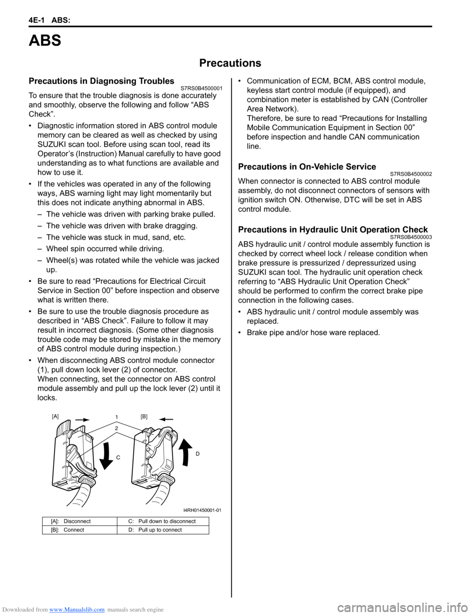
• When disconnecting ABS co ntrol module connector
(1), pull down lock lever (2) of connector.
When connecting, set the connector on ABS control
module assembly and pull up the lock lever (2) until it
locks. • Communication of ECM,
BCM, ABS control module,
keyless start control module (if equipped), and
combination meter is established by CAN (Controller
Area Network).
Therefore, be sure to read “Precautions for Installing
Mobile Communication Equipment in Section 00”
before inspection and handle CAN communication
line.
Precautions in On-Vehicle ServiceS7RS0B4500002
When connector is connected to ABS control module
assembly, do not disconnect connectors of sensors with
ignition switch ON. Otherwise, DTC will be set in ABS
control module.
Precautions in Hydraulic Unit Operation CheckS7RS0B4500003
ABS hydraulic unit / control module assembly function is
checked by correct wheel lock / release condition when
brake pressure is pressurized / depressurized using
SUZUKI scan tool. The hydraulic unit operation check
referring to “ABS Hydraulic Unit Operation Check”
should be performed to confirm the correct brake pipe
connection in the following cases.
• ABS hydraulic unit / cont rol module assembly was
replaced.
• Brake pipe and/or hose ware replaced.
[A]: Disconnect C: Pull down to disconnect
[B]: Connect D: Pull up to connect
21
C D
[A]
[B]
I4RH01450001-01
Page 551 of 1496

Downloaded from www.Manualslib.com manuals search engine ABS: 4E-12
DTC ClearanceS7RS0B4504006
WARNING!
When performing a driving test, select a safe
place where there is neither any traffic nor
any traffic accident possibility and be very
careful during testing to avoid occurrence of
an accident.
After repair or replace malfunction part(s), clear all DTCs
by performing the following procedure or using SUZUKI
scan tool.
1) Connect SUZUKI scan tool to data link connector in the same manner as when making this connection
for DTC check.
2) Turn ignition switch to ON position.
3) Erase DTC according to instructions displayed on scan tool. Refer to scan tool operator’s manual for
further derails.
NOTE
For DTC C 1021, C1022, C1025, C1026, C1031,
C1032, C1035, C1036 and C1061, confirm that
ABS warning light turns off after performing
Step 2 of “Test Driving” under “ABS Check”,
and then clear the DTCs.
4) After completing the clear ance, turn ignition switch
OFF and disconnect scan tool from data link
connector.
5) Perform “Driving Test” (S tep 2 of “ABS Check”) and
“DTC Check” and confirm that NO DTC is displayed
on scan tool.
Scan Tool DataS7RS0B4504007
The parameter data below are values measured with the
scan tool when the normally operating vehicle is under
the following conditions. When taking measurements for
comparison by using the scan tool, be sure to check that
the vehicle is under the following conditions.
• Apply parking brake and block wheels.
• Ignition switch ON.
• Turn OFF air conditioner (if equipped).
• Apply no load to power steering (if equipped). (Don’t turn it)
• Turn OFF all electric loads (except ignition).
• No DTC.
• ABS is not operated. (N ormal braking operation)
Scan Tool Data Definition
Battery Volt (V): Battery Voltage is an analog input
signal read by the ABS control module. Certain ABS
control module function s will be modified if the
battery voltage falls below or rises above
programmed thresholds.
Pump Motor Driver (V): This parameter indicates the
operational condition of the pump motor driver
(transistor).
RF Wheel Speed, LF Wheel Speed, RR Wheel Speed and LF Wheel Speed (km/h, MPH): Wheel speed
is an ABS control module inte rnal parameter. It is
computed by reference pulses from the wheel speed
sensor.
Brake Switch (ON, OFF): This switch signal informs
the ABS control modu le whether the brake is active
or not.
Scan Tool
Data Standards Condition
Battery
Voltage 10.0 – 18.0 V —
Pump Motor
Driver 0.0 V —
RF Wheel
Sp ee d 0 km/h, 0.0 MPH Vehicle stop
LF Wheel
Sp ee d 0 km/h, 0.0 MPH Vehicle stop
RR Wheel
Sp ee d 0 km/h, 0.0 MPH Vehicle stop
LR Wheel
Sp ee d 0 km/h, 0.0 MPH Vehicle stop
Brake Switch ONBrake pedal
depressed
OFF Brake pedal released
Page 552 of 1496

Downloaded from www.Manualslib.com manuals search engine 4E-13 ABS:
ABS Warning Light Does Not Come ON at Ignition Switch ONS7RS0B4504008
Wiring Diagram
Circuit Description
Operation (ON/OFF) of ABS warning light is controlled by ABS contro l module through lamp driver module in
combination meter.
If the antilock brake system is in good condition, ABS control module turns ABS warning light ON at the ignition switch
ON, keeps it ON for 2 seconds and then turns it OFF. If an abnormality in the system is detected, ABS warning light is
turned ON continuously by ABS control module. Also, it is turned ON continuously by la mp driver module when the
connector of ABS control module is disconnected.
Troubleshooting
WHT/BLU
BLK 12V
9
BLK
E03-14
E03-13
E03-26
WHT/RED
GRN/ORNE03-7WHT/BLUGRN
1
2
3
48
RED/BLK
76
5
10
E03-112V[A]
E03
15
16
17
18
19
20
21
22
23
24
25 2
3
4
5
6
7
8
9
10
11
12
1
13
14
26
BLK/ORN
E03-12
E03-6
REDWHT
10
G28-8
G28-10
REDWHTE46-1
E46-2
RED/BLK
RED/BLK
RED
RED
WHT
WHT
12
13
11
10
G37-2
G37-4
I6RS0C450007-01
[A]: ABS hydraulic unit / control module connector (viewed from terminal side) 5. Combination meter 10. CAN driver
1. Battery 6. ABS warning light 11. BCM
2. Main fuse box 7. EBD warning light (Brake warning light) 12. Brake fluid level switch
3. Ignition switch 8. Lamp driver module 13. Parking brake switch
4. Circuit fuse box 9. ABS hydraulic unit / control module assembly
Step Action YesNo
1 1) Turn ignition switch to ON position.
Do other warning lights come ON? Go to Step 2.
Go to Step 3.
2 1) Connect scan tool to DLC with ignition switch turned OFF.
2) Turn ignition switch to ON position and check DTC.
Is there DTC U1073? Go to “DTC U1073:
Control Module
Communication Bus
Off”.
Substitute a known-
good combination meter
and recheck. If ABS
warning light remains
OFF, substitute a
known-good ABS
hydraulic unit / control
module assembly and
recheck.
3 Is Circuit fuse fo r combination meter in good condition? Go to Step 4.Replace fuse and check
for short circuit to
ground.
Page 553 of 1496
Downloaded from www.Manualslib.com manuals search engine ABS: 4E-14
ABS Warning Light Comes ON SteadyS7RS0B4504009
Wiring Diagram
Refer to “ABS Warning Light Does Not Come ON at Ignition Switch ON”.
Circuit Description
Operation (ON/OFF) of ABS wa rning light is controlled by ABS contro l module through lamp driver module in
combination meter.
If the Antilock brake system is in good condition, ABS control module turns ABS warning lig ht ON at the ignition switch
ON, keeps it ON for 2 seconds and then turns it OFF. If an abnormality in the system is detected, ABS warning light is
turned ON continuously by ABS c ontrol module. Also, it is turned ON continuously by la mp driver module when the
connector of ABS control module is disconnected.
Troubleshooting 4 Check CAN communication circuit between combination
meter and ABS control module referring to “DTC U1073:
Control Module Communication Bus Off”.
Is CAN communication circuit in good condition? Go to Step 5.
Repair or replace.
5 1) Remove combination meter wit h ignition switch turned
OFF.
2) Check for proper connection to “RED/BLK” and “BLK/ ORN” wire of combinat ion meter connector.
3) If OK, turn ON ignition switch and measure voltage at “PPL/RED” wire of combi nation meter connector and
vehicle body ground.
Is it 10 – 14 V? Go to Step 6.
Repair power supply
circuit for combination
meter.
6 1) Measure resistance between “BLK/ORN” wire of combination meter connector and vehicle body ground.
Is resistance less than 2
Ω? Replace combination
meter.
“BLK/ORN” circuit open
or high resistance.
Step Action Yes No
Step
Action YesNo
1 1) Perform diagnostic trouble code check.
Is there any DTC(s)? Go to applicable DTC
diag. flow.
Go to Step 2.
2 Are main fuses for ABS pump motor and ABS solenoid in
good condition? Go to Step 3.
Replace fuse and check
circuit for short to
ground.
3 1) Turn ignition switch to OFF.
2) Disconnect ABS control module connector.
3) Check for proper connection to ABS control module connector at terminals “E03-7”, “E03-13” and “E03-26”.
4) If OK then turn ignition switch to ON position and measure voltage between terminal “E03-7” and vehicle
body ground.
Is it 10 – 14 V? Go to Step 4.
“GRN/ORN” circuit
open.
4 1) Turn ignition switch to OFF position. 2) Check for proper connection to ABS control module connector at terminals “E03-1” and “E03-14”.
3) If OK then turn ignition switch to ON position and measure voltage between each terminal of “E03-1”,
“E03-14” and vehicle body ground.
Are they 10 – 14 V? Go to Step 5.
“WHT/RED” and/or
“WHT/BLU” circuit
open.
Page 567 of 1496
Downloaded from www.Manualslib.com manuals search engine ABS: 4E-28
Repair Instructions
ABS Hydraulic Unit Operation CheckS7RS0B4506001
1) Check that basic brake system other than ABS is in good condition.
2) Check that battery voltage is 11 V or higher.
3) Lift up vehicle.
4) Set transmission to neutral and release parking brake.
5) Turn each wheel gradually by hand to check if brake dragging occurs. If it does, correct.
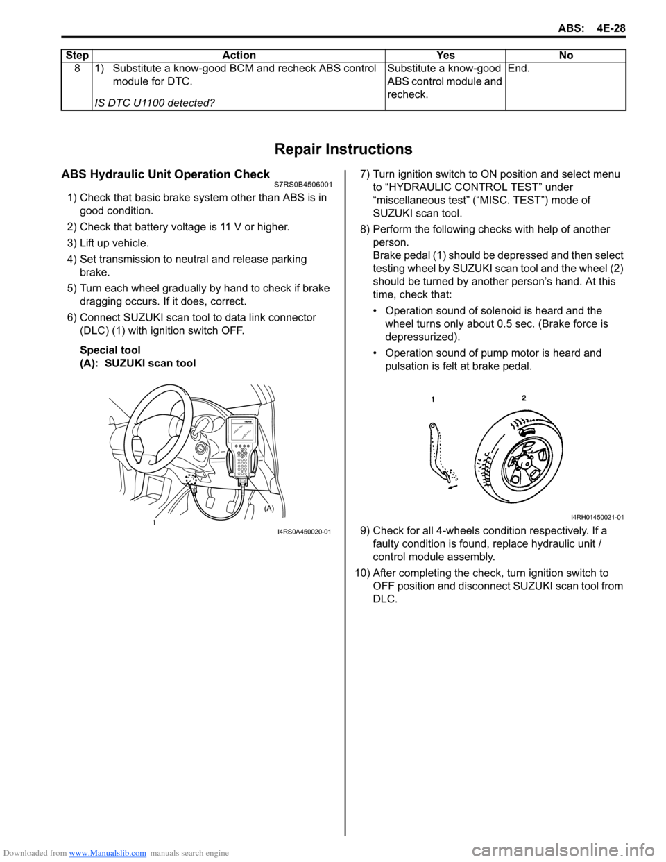
6) Connect SUZUKI scan tool to data link connector (DLC) (1) with ignition switch OFF.
Special tool
(A): SUZUKI scan tool 7) Turn ignition switch to ON position and select menu
to “HYDRAULIC CONTROL TEST” under
“miscellaneous test” (“MISC. TEST”) mode of
SUZUKI scan tool.
8) Perform the following checks with help of another person.
Brake pedal (1) should be depressed and then select
testing wheel by SUZUKI scan tool and the wheel (2)
should be turned by another person’s hand. At this
time, check that:
• Operation sound of solenoid is heard and the wheel turns only about 0.5 sec. (Brake force is
depressurized).
• Operation sound of pump motor is heard and pulsation is felt at brake pedal.
9) Check for all 4-wheels co ndition respectively. If a
faulty condition is found, replace hydraulic unit /
control module assembly.
10) After completing the check, turn ignition switch to OFF position and disconnect SUZUKI scan tool from
DLC.
8 1) Substitute a know-good BCM and recheck ABS control
module for DTC.
IS DTC U1100 detected? Substitute a know-good
ABS control module and
recheck.
End.
Step Action Yes No
1 (A)I4RS0A450020-01
I4RH01450021-01
Page 569 of 1496
Downloaded from www.Manualslib.com manuals search engine ABS: 4E-30
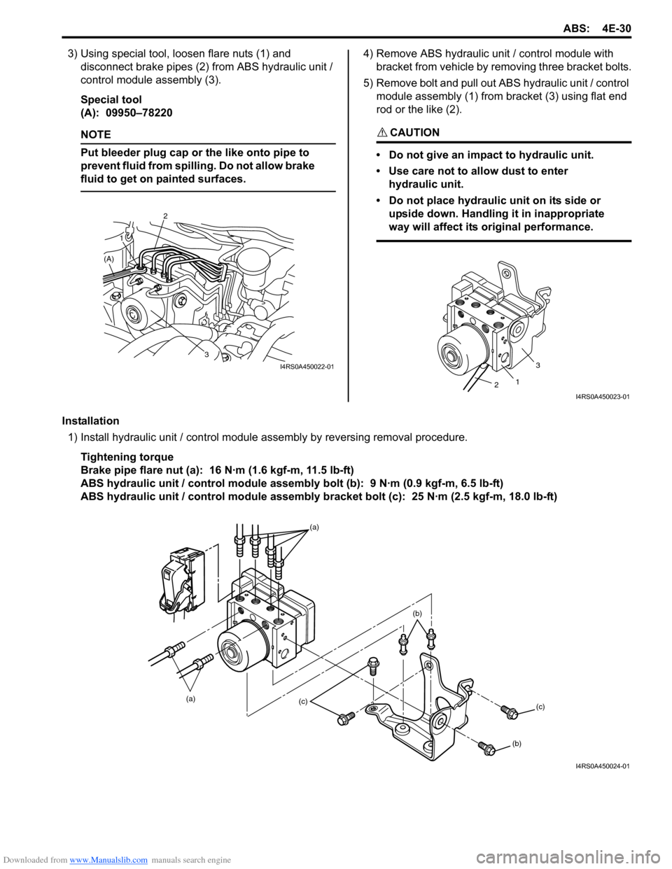
3) Using special tool, loosen flare nuts (1) and disconnect brake pipes (2) from ABS hydraulic unit /
control module assembly (3).
Special tool
(A): 09950–78220
NOTE
Put bleeder plug cap or the like onto pipe to
prevent fluid from spilli ng. Do not allow brake
fluid to get on painted surfaces.
4) Remove ABS hydraulic unit / control module with
bracket from vehicle by removing three bracket bolts.
5) Remove bolt and pull out ABS hydraulic unit / control module assembly (1) from bracket (3) using flat end
rod or the like (2).
CAUTION!
• Do not give an impact to hydraulic unit.
• Use care not to allow dust to enter hydraulic unit.
• Do not place hydraulic unit on its side or upside down. Handling it in inappropriate
way will affect its original performance.
Installation
1) Install hydraulic unit / control module assembly by reversing removal procedure.
Tightening torque
Brake pipe flare nut (a): 16 N·m (1.6 kgf-m, 11.5 lb-ft)
ABS hydraulic unit / control module assembly bolt (b): 9 N·m (0.9 kgf-m, 6.5 lb-ft)
ABS hydraulic unit / control module assembly bracket bolt (c): 25 N·m (2.5 kgf-m, 18.0 lb-ft)
3
2
1
(A)
I4RS0A450022-01
1
3
2
I4RS0A450023-01
(a) (a)(c)
(c)
(b)
(b)
I4RS0A450024-01
Page 570 of 1496
Downloaded from www.Manualslib.com manuals search engine 4E-31 ABS:
2) Bleed air from brake system referring to “Air Bleeding of Brake System in Section 4A”.
3) Check each installed part for fluid leakage and perform “ABS Hydraulic Un it Operation Check”.
NOTE
For new ABS hydraulic unit / control module
assembly, if “ABS Hydraulic Unit Operation
Check” has not been performed, ABS
warning light may flash when ignition switch
is turned ON position.
Accordingly preform “ABS Hydraulic Unit
Operation Check” to stop flashing of ABS
warning light.
Front / Rear Wheel Speed Sensor On-Vehicle
Inspection
S7RS0B4506005
Output Voltage Inspection
1) Disconnect negative cable from battery.
2) Hoist vehicle a little.
3) Disconnect wheel speed sensor connector.
4) Disconnect wheel speed grommet from vehicle body.
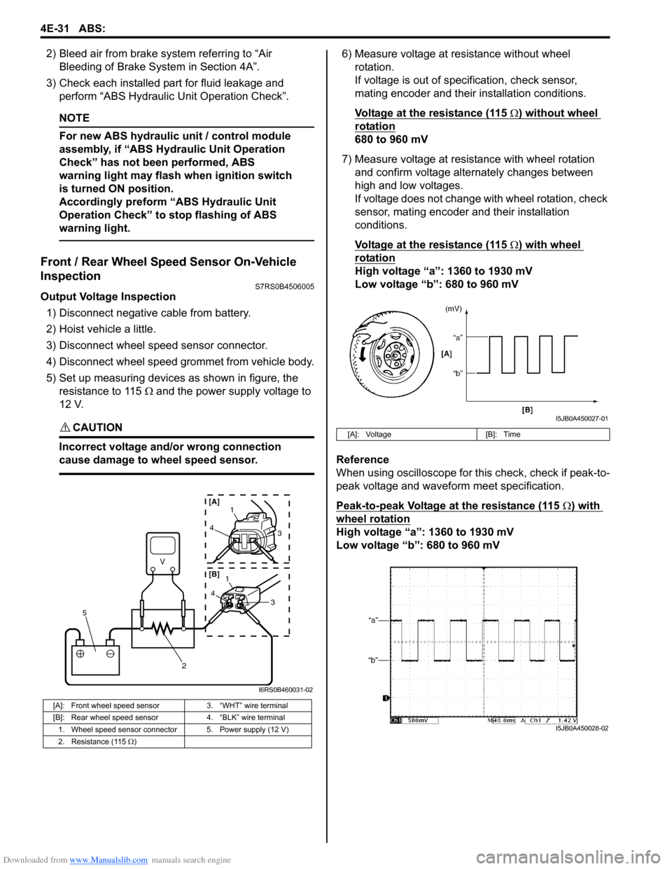
5) Set up measuring devices as shown in figure, the resistance to 115 Ω and the power supply voltage to
12 V.
CAUTION!
Incorrect voltage and/or wrong connection
cause damage to wheel speed sensor.
6) Measure voltage at resistance without wheel rotation.
If voltage is out of specification, check sensor,
mating encoder and their installation conditions.
Voltage at the resistance (115
Ω) without wheel
rotation
680 to 960 mV
7) Measure voltage at resistance with wheel rotation and confirm voltage alternately changes between
high and low voltages.
If voltage does not change with wheel rotation, check
sensor, mating encoder and their installation
conditions.
Voltage at the resistance (115
Ω) with wheel
rotation
High voltage “a”: 1360 to 1930 mV
Low voltage “b”: 680 to 960 mV
Reference
When using oscilloscope for this check, check if peak-to-
peak voltage and waveform meet specification.
Peak-to-peak Voltage at the resistance (115
Ω) with
wheel rotation
High voltage “a”: 1360 to 1930 mV
Low voltage “b”: 680 to 960 mV
[A]: Front wheel speed sensor 3. “WHT” wire terminal
[B]: Rear wheel speed sensor 4. “BLK” wire terminal
1. Wheel speed sensor connector 5. Power supply (12 V)
2. Resistance (115 Ω )
V
2
5
41
3
43
1
[A]
[B]
I6RS0B460031-02
[A]: Voltage [B]: Time
I5JB0A450027-01
I5JB0A450028-02