2007 SUZUKI SWIFT Gas
[x] Cancel search: GasPage 425 of 1496
Downloaded from www.Manualslib.com manuals search engine Exhaust System: 1K-2
Repair Instructions
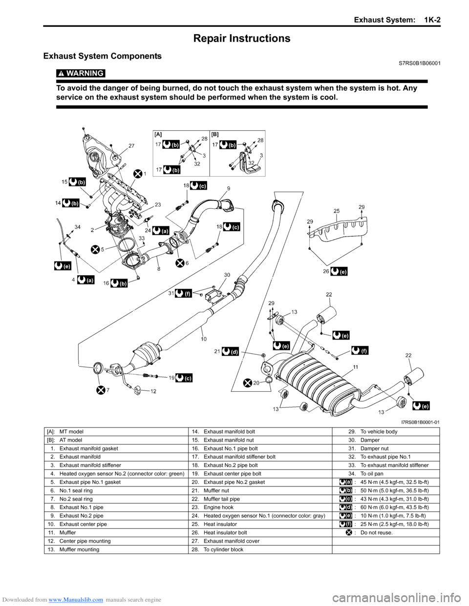
Exhaust System ComponentsS7RS0B1B06001
WARNING!
To avoid the danger of being burned, do not touch the exhaust system when the system is hot. Any
service on the exhaust system should be performed when the system is cool.
I7RS0B1B0001-01
[A]: MT model14. Exhaust manifold bolt 29. To vehicle body
[B]: AT model 15. Exhaust manifold nut 30. Damper
1. Exhaust manifold gasket 16. Exhaust No.1 pipe bolt 31. Damper nut
2. Exhaust manifold 17. Exhaust manifold stiffener bolt 32. To exhaust pipe No.1
3. Exhaust manifold stiffener 18. Exhaust No.2 pipe bolt 33. To exhaust manifold stiffener
4. Heated oxygen sensor No.2 (connector color: green) 19. Exhaust center pipe bolt 34. To oil pan
5. Exhaust pipe No.1 gasket 20. Exhaust pipe No.2 gasket : 45 N⋅m (4.5 kgf-m, 32.5 lb-ft)
6. No.1 seal ring 21. Muffler nut : 50 N⋅m (5.0 kgf-m, 36.5 lb-ft)
7. No.2 seal ring 22. Muffler tail pipe : 43 N⋅m (4.3 kgf-m, 31.0 lb-ft)
8. Exhaust No.1 pipe 23. Engine hook : 60 N⋅m (6.0 kgf-m, 43.5 lb-ft)
9. Exhaust No.2 pipe 24. Heated oxygen sensor No.1 (connector color: gray) : 10 N⋅m (1.0 kgf-m, 7.5 lb-ft)
10. Exhaust center pipe 25. Heat insulator : 25 N⋅m (2.5 kgf-m, 18.0 lb-ft)
11. Muffler 26. Heat insulator bolt : Do not reuse.
12. Center pipe mounting 27. Exhaust manifold cover
13. Muffler mounting 28. To cylinder block
Page 426 of 1496
Downloaded from www.Manualslib.com manuals search engine 1K-3 Exhaust System:
Exhaust Manifold Removal and InstallationS7RS0B1B06002
Removal
WARNING!
To avoid danger of being burned, do not
service exhaust system while it is still hot.
Service should be performed after system
cools down.
1) Disconnect negative cable at battery.
2) Remove engine cover.
3) Remove front bumper with front grille referring to
“Front Bumper and Rear Bumper Components in
Section 9K”.
4) Remove radiator referring to “Radiator Removal and Installation in Section 1F ” for equipped with A/C.
5) With hose connected, detach A/C condenser from vehicle body for equipped with A/C.
6) Remove exhaust manifold cover from exhaust manifold.
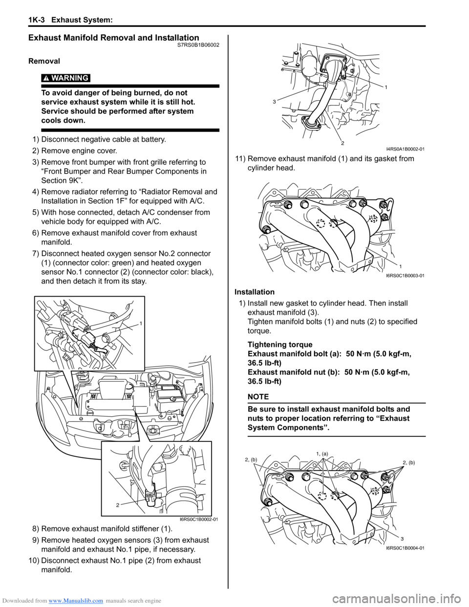
7) Disconnect heated oxygen sensor No.2 connector (1) (connector color: green) and heated oxygen
sensor No.1 connector (2) (connector color: black),
and then detach it from its stay.
8) Remove exhaust manifold stiffener (1).
9) Remove heated oxygen sensors (3) from exhaust manifold and exhaust No.1 pipe, if necessary.
10) Disconnect exhaust No.1 pipe (2) from exhaust manifold. 11) Remove exhaust manifold (1) and its gasket from
cylinder head.
Installation 1) Install new gasket to cylinder head. Then install exhaust manifold (3).
Tighten manifold bolts (1) and nuts (2) to specified
torque.
Tightening torque
Exhaust manifold bolt (a): 50 N·m (5.0 kgf-m,
36.5 lb-ft)
Exhaust manifold nut (b): 50 N·m (5.0 kgf-m,
36.5 lb-ft)
NOTE
Be sure to install exhaust manifold bolts and
nuts to proper location referring to “Exhaust
System Components”.
1
2
I6RS0C1B0002-01
1
2
3
I4RS0A1B0002-01
1
I6RS0C1B0003-01
2, (b) 2, (b)
3
1, (a)
I6RS0C1B0004-01
Page 427 of 1496
Downloaded from www.Manualslib.com manuals search engine Exhaust System: 1K-4
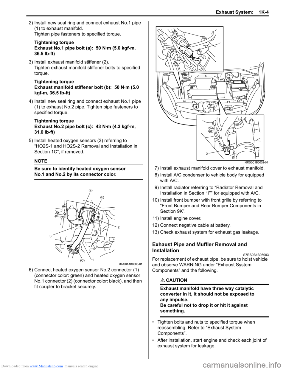
2) Install new seal ring and connect exhaust No.1 pipe (1) to exhaust manifold.
Tighten pipe fasteners to specified torque.
Tightening torque
Exhaust No.1 pipe bolt (a): 50 N·m (5.0 kgf-m,
36.5 lb-ft)
3) Install exhaust manifold stiffener (2). Tighten exhaust manifold stiffener bolts to specified
torque.
Tightening torque
Exhaust manifold stiffener bolt (b): 50 N·m (5.0
kgf-m, 36.5 lb-ft)
4) Install new seal ring and connect exhaust No.1 pipe (1) to exhaust No.2 pipe. Tighten pipe fasteners to
specified torque.
Tightening torque
Exhaust No.2 pipe bolt (c): 43 N·m (4.3 kgf-m,
31.0 lb-ft)
5) Install heated oxygen sensors (3) referring to “HO2S-1 and HO2S-2 Removal and Installation in
Section 1C”, if removed.
NOTE
Be sure to identify heated oxygen sensor
No.1 and No.2 by its connector color.
6) Connect heated oxygen sensor No.2 connector (1)
(connector color: green) and heated oxygen sensor
No.1 connector (2) (connector color: black), and then
fit coupler to br acket securely. 7) Install exhaust manifold cover to exhaust manifold.
8) Install A/C condenser to vehicle body for equipped
with A/C.
9) Install radiator referrin g to “Radiator Removal and
Installation in Section 1F” for equipped with A/C.
10) Install front bumper with fr ont grille by referring to
“Front Bumper and Rear Bumper Components in
Section 9K”.
11) Install engine cover.
12) Connect negative cable at battery.
13) Check exhaust system for exhaust gas leakage.
Exhaust Pipe and Muffler Removal and
Installation
S7RS0B1B06003
For replacement of exhaust pipe, be sure to hoist vehicle
and observe WARNING under “Exhaust System
Components” and the following.
CAUTION!
Exhaust manifold have three way catalytic
converter in it, it should not be exposed to
any impulse.
Be careful not to drop it or hit it against
something.
• Tighten bolts and nuts to specified torque when reassembling. Refer to “Exhaust System
Components”.
• After installation, start engine and check each joint of exhaust system for leakage.
2
(b)
(a)
1(C)
3
I4RS0A1B0005-01
1
2
I6RS0C1B0002-01
Page 457 of 1496
Downloaded from www.Manualslib.com manuals search engine Rear Suspension: 2C-3
2) Remove floor jack (2) from rear axle.
3) Install rear wheels and tighten wheel nuts specified torque.
Tightening torque
Wheel nut: 85 N·m (8.5 kgf-m, 61.5 lb-ft)
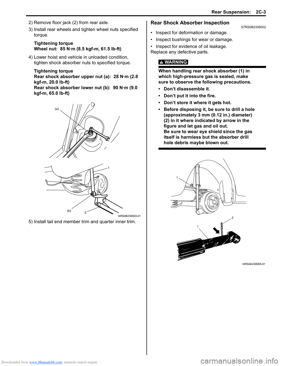
4) Lower hoist and vehicle in unloaded condition, tighten shock absorber nuts to specified torque.
Tightening torque
Rear shock absorber upper nut (a): 28 N·m (2.8
kgf-m, 20.0 lb-ft)
Rear shock absorber lower nut (b): 90 N·m (9.0
kgf-m, 65.0 lb-ft)
5) Install tail end member trim and quarter inner trim.Rear Shock Absorber InspectionS7RS0B2306002
• Inspect for deformation or damage.
• Inspect bushings for wear or damage.
• Inspect for evidence of oil leakage.
Replace any defective parts.
WARNING!
When handling rear shock absorber (1) in
which high-pressure gas is sealed, make
sure to observe the following precautions.
• Don’t disassemble it.
• Don’t put it into the fire.
• Don’t store it where it gets hot.
• Before disposing it, be sure to drill a hole (approximately 3 mm (0.12 in.) diameter)
(2) in it where indicated by arrow in the
figure and let gas and oil out.
Be sure to wear eye shield since the gas
itself is harmless but the absorber drill
hole debris maybe blown out.
(a)
1
(b) 2
I4RS0B230003-01
I4RS0A230005-01
Page 486 of 1496
Downloaded from www.Manualslib.com manuals search engine 3A-8 Drive Shaft / Axle:
Reassembly
Tripod joint
Judging from abnormality noted before disassembly and
what is found through visual check of component parts
after disassembly, prepare replacing parts and proceed
to reassembly.
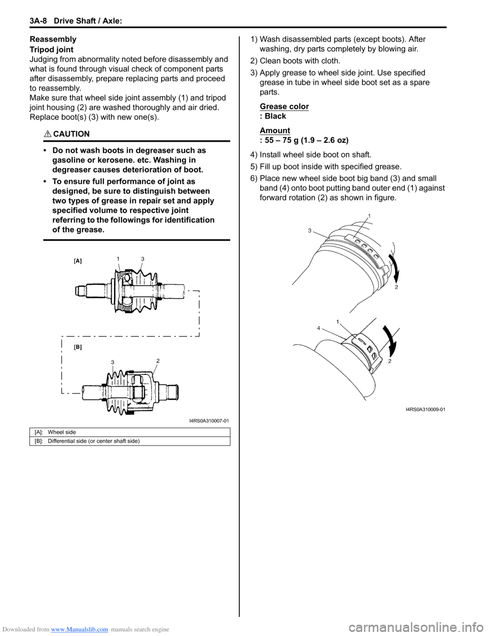
Make sure that wheel side joint assembly (1) and tripod
joint housing (2) are washed thoroughly and air dried.
Replace boot(s) (3) with new one(s).
CAUTION!
• Do not wash boots in degreaser such as gasoline or kerosene. etc. Washing in
degreaser causes deterioration of boot.
• To ensure full performance of joint as designed, be sure to distinguish between
two types of grease in repair set and apply
specified volume to respective joint
referring to the followings for identification
of the grease.
1) Wash disassembled parts (except boots). After washing, dry parts comp letely by blowing air.
2) Clean boots with cloth.
3) Apply grease to wheel side joint. Use specified grease in tube in wheel side boot set as a spare
parts.
Grease color
: Black
Amount
: 55 – 75 g (1.9 – 2.6 oz)
4) Install wheel side boot on shaft.
5) Fill up boot inside with specified grease.
6) Place new wheel side boot big band (3) and small band (4) onto boot putting band outer end (1) against
forward rotation (2) as shown in figure.
[A]: Wheel side
[B]: Differential side (or center shaft side)
I4RS0A310007-01
I4RS0A310009-01
Page 489 of 1496
Downloaded from www.Manualslib.com manuals search engine Drive Shaft / Axle: 3A-11
DOJ
Judging from abnormality noted before disassembly and
what is found through visual check of components parts
after disassembly, prepare replacing parts and proceed
to reassembly.
Make sure that wheel side joint assembly and DOJ
housing are washed thoroughly and air dried.
Replace boot(s) with new one(s).
CAUTION!
• Do not wash boots in degreaser such as gasoline or kerosene. etc. Washing in
degreaser causes deterioration of boot.
• To ensure full performance of joint as designed, be sure to distinguish between
two types of grease in repair set and apply
specified volume to respective joint
referring to the followings for identification
of the grease.
1) Wash disassembled parts (except boots). After washing, dry parts completely by blowing air.
2) Clean boots with cloth.
3) Apply grease to wheel side joint. Use specified
grease in tube in wheel side boot set as a spare
parts.
Grease color
: Black
Amount
: 55 – 75 g (1.9 – 2.6 oz)
4) Install wheel side boot on shaft.
5) Fill up boot inside wi th specified grease.
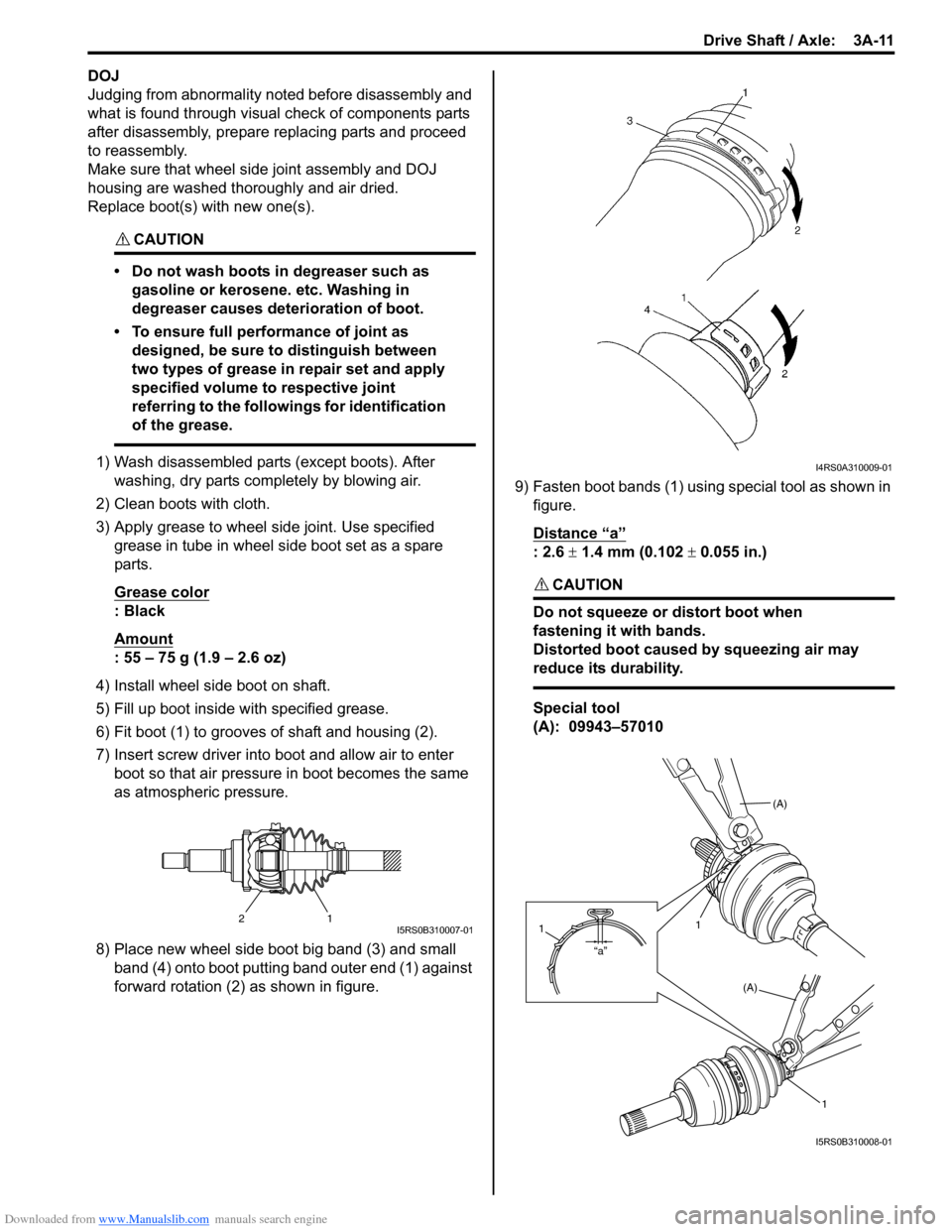
6) Fit boot (1) to grooves of shaft and housing (2).
7) Insert screw driver into boot and allow air to enter boot so that air pressure in boot becomes the same
as atmospheric pressure.
8) Place new wheel side boot big band (3) and small band (4) onto boot putting band outer end (1) against
forward rotation (2) as shown in figure. 9) Fasten boot bands (1) using special tool as shown in
figure.
Distance “a”
: 2.6 ± 1.4 mm (0.102 ± 0.055 in.)
CAUTION!
Do not squeeze or distort boot when
fastening it with bands.
Distorted boot caused by squeezing air may
reduce its durability.
Special tool
(A): 09943–57010
21I5RS0B310007-01
I4RS0A310009-01
(A)
1
(A)
1
“a”
1
I5RS0B310008-01
Page 512 of 1496
Downloaded from www.Manualslib.com manuals search engine 4A-14 Brake Control System and Diagnosis:
6) Fill reservoir with specified fluid.
7) After completing the work, bleed air from brake and clutch system referring to “Air Bleeding of Brake
System” and “Air Bleeding of Clutch System in
Section 5C” (M/T model).
8) Install cowl top panel referring to “Cowl Top Components in Section 9K”.
9) Install windshield wiper referring to “Windshield
Wiper Removal and Insta llation in Section 9D”.
10) Perform brake test and check each installed part for fluid leakage.
Master Cylinder Assembly Disassembly and
Assembly
S7RS0B4106013
Disassembly
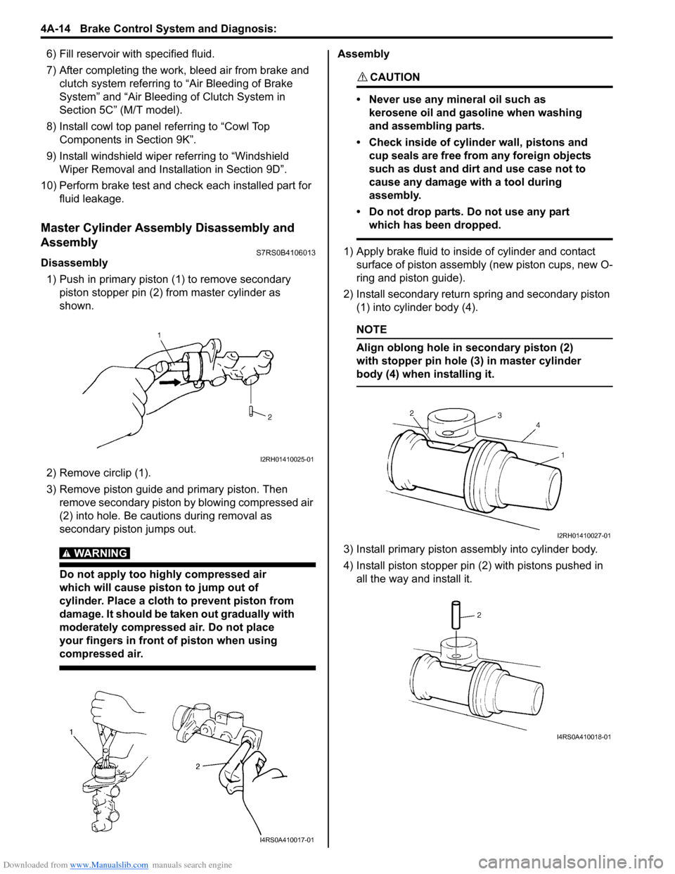
1) Push in primary piston (1) to remove secondary
piston stopper pin (2) from master cylinder as
shown.
2) Remove circlip (1).
3) Remove piston guide and primary piston. Then remove secondary piston by blowing compressed air
(2) into hole. Be cautions during removal as
secondary piston jumps out.
WARNING!
Do not apply too highly compressed air
which will cause piston to jump out of
cylinder. Place a cloth to prevent piston from
damage. It should be taken out gradually with
moderately compressed air. Do not place
your fingers in front of piston when using
compressed air.
Assembly
CAUTION!
• Never use any mineral oil such as kerosene oil and gasoline when washing
and assembling parts.
• Check inside of cylinder wall, pistons and cup seals are free from any foreign objects
such as dust and dirt and use case not to
cause any damage with a tool during
assembly.
• Do not drop parts. Do not use any part which has been dropped.
1) Apply brake fluid to inside of cylinder and contact surface of piston assembly (new piston cups, new O-
ring and piston guide).
2) Install secondary return spring and secondary piston (1) into cylinder body (4).
NOTE
Align oblong hole in secondary piston (2)
with stopper pin hole (3) in master cylinder
body (4) when installing it.
3) Install primary piston assembly into cylinder body.
4) Install piston stopper pin (2) with pistons pushed in all the way and install it.
I2RH01410025-01
I4RS0A410017-01
I2RH01410027-01
I4RS0A410018-01
Page 513 of 1496
Downloaded from www.Manualslib.com manuals search engine Brake Control System and Diagnosis: 4A-15
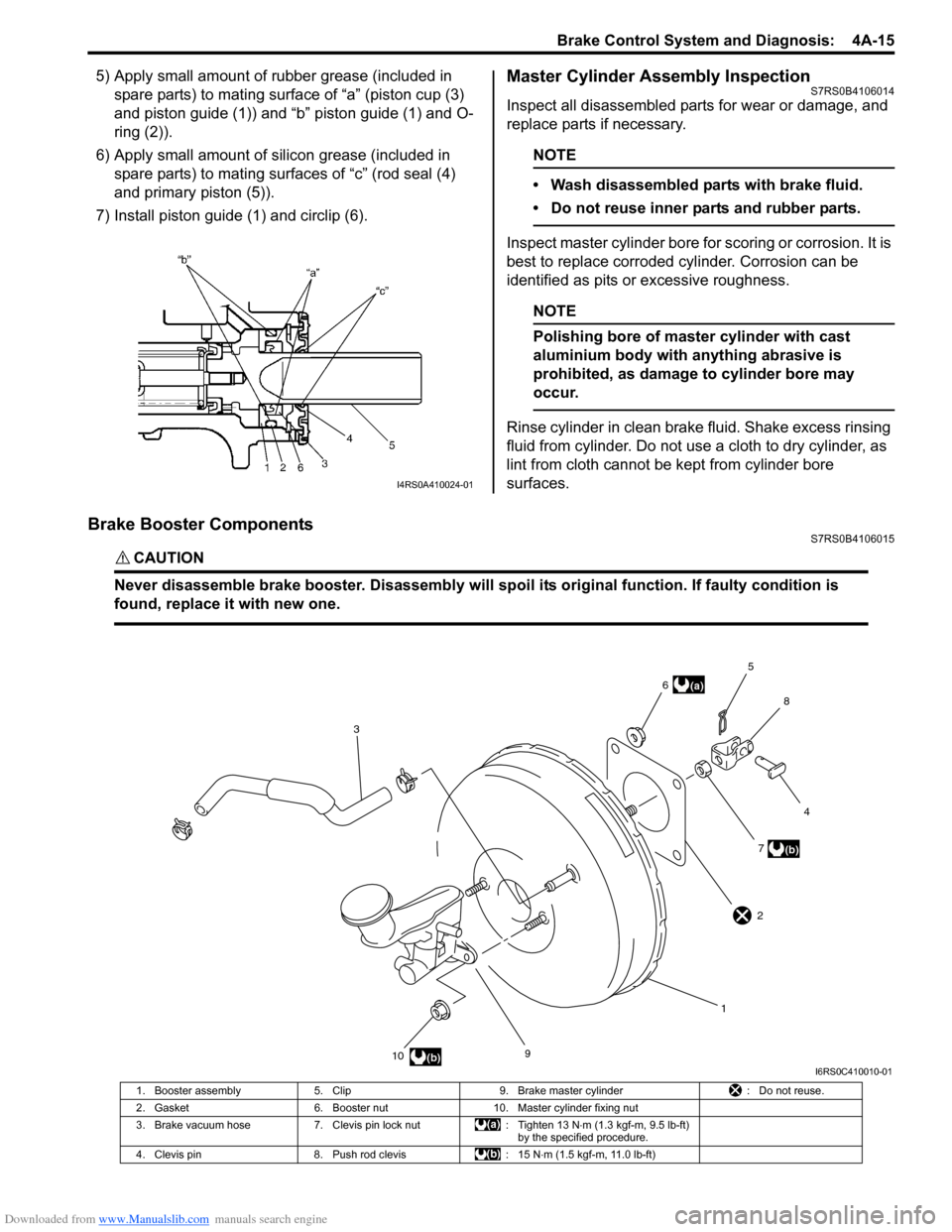
5) Apply small amount of rubber grease (included in spare parts) to mating surface of “a” (piston cup (3)
and piston guide (1)) and “b” piston guide (1) and O-
ring (2)).
6) Apply small amount of s ilicon grease (included in
spare parts) to mating surfaces of “c” (rod seal (4)
and primary piston (5)).
7) Install piston guide (1) and circlip (6).Master Cylinder Assembly InspectionS7RS0B4106014
Inspect all disassembled parts for wear or damage, and
replace parts if necessary.
NOTE
• Wash disassembled parts with brake fluid.
• Do not reuse inner parts and rubber parts.
Inspect master cylinder bore for scoring or corrosion. It is
best to replace corroded cylinder. Corrosion can be
identified as pits or excessive roughness.
NOTE
Polishing bore of master cylinder with cast
aluminium body with anything abrasive is
prohibited, as damage to cylinder bore may
occur.
Rinse cylinder in clean brake fluid. Shake excess rinsing
fluid from cylinder. Do not use a cloth to dry cylinder, as
lint from cloth cannot be kept from cylinder bore
surfaces.
Brake Booster ComponentsS7RS0B4106015
CAUTION!
Never disassemble brake booster. Disassembly will spoi l its original function. If faulty condition is
found, replace it with new one.
I4RS0A410024-01
9
10 17
4
8
5
6
3
(b)
(a)
(b)
2
I6RS0C410010-01
1. Booster assembly 5. Clip 9. Brake master cylinder : Do not reuse.
2. Gasket 6. Booster nut 10. Master cylinder fixing nut
3. Brake vacuum hose 7. Clevis pin lock nut : Tighten 13 N⋅m (1.3 kgf-m, 9.5 lb-ft)
by the specified procedure.
4. Clevis pin 8. Push rod clevis : 15 N⋅m (1.5 kgf-m, 11.0 lb-ft)