2007 SUZUKI SWIFT radiator
[x] Cancel search: radiatorPage 427 of 1496
Downloaded from www.Manualslib.com manuals search engine Exhaust System: 1K-4
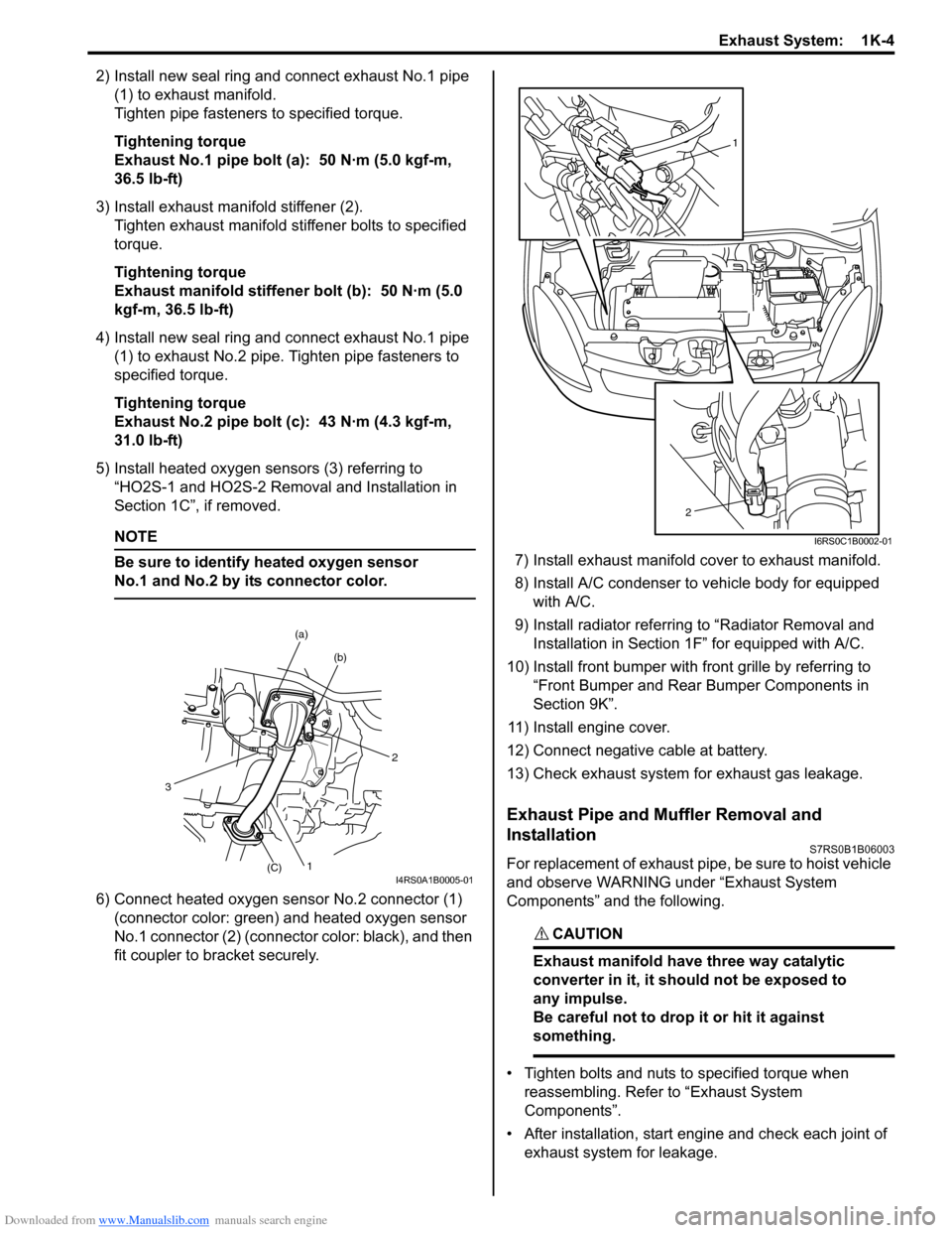
2) Install new seal ring and connect exhaust No.1 pipe (1) to exhaust manifold.
Tighten pipe fasteners to specified torque.
Tightening torque
Exhaust No.1 pipe bolt (a): 50 N·m (5.0 kgf-m,
36.5 lb-ft)
3) Install exhaust manifold stiffener (2). Tighten exhaust manifold stiffener bolts to specified
torque.
Tightening torque
Exhaust manifold stiffener bolt (b): 50 N·m (5.0
kgf-m, 36.5 lb-ft)
4) Install new seal ring and connect exhaust No.1 pipe (1) to exhaust No.2 pipe. Tighten pipe fasteners to
specified torque.
Tightening torque
Exhaust No.2 pipe bolt (c): 43 N·m (4.3 kgf-m,
31.0 lb-ft)
5) Install heated oxygen sensors (3) referring to “HO2S-1 and HO2S-2 Removal and Installation in
Section 1C”, if removed.
NOTE
Be sure to identify heated oxygen sensor
No.1 and No.2 by its connector color.
6) Connect heated oxygen sensor No.2 connector (1)
(connector color: green) and heated oxygen sensor
No.1 connector (2) (connector color: black), and then
fit coupler to br acket securely. 7) Install exhaust manifold cover to exhaust manifold.
8) Install A/C condenser to vehicle body for equipped
with A/C.
9) Install radiator referrin g to “Radiator Removal and
Installation in Section 1F” for equipped with A/C.
10) Install front bumper with fr ont grille by referring to
“Front Bumper and Rear Bumper Components in
Section 9K”.
11) Install engine cover.
12) Connect negative cable at battery.
13) Check exhaust system for exhaust gas leakage.
Exhaust Pipe and Muffler Removal and
Installation
S7RS0B1B06003
For replacement of exhaust pipe, be sure to hoist vehicle
and observe WARNING under “Exhaust System
Components” and the following.
CAUTION!
Exhaust manifold have three way catalytic
converter in it, it should not be exposed to
any impulse.
Be careful not to drop it or hit it against
something.
• Tighten bolts and nuts to specified torque when reassembling. Refer to “Exhaust System
Components”.
• After installation, start engine and check each joint of exhaust system for leakage.
2
(b)
(a)
1(C)
3
I4RS0A1B0005-01
1
2
I6RS0C1B0002-01
Page 649 of 1496
Downloaded from www.Manualslib.com manuals search engine Automatic Transmission/Transaxle: 5A-5
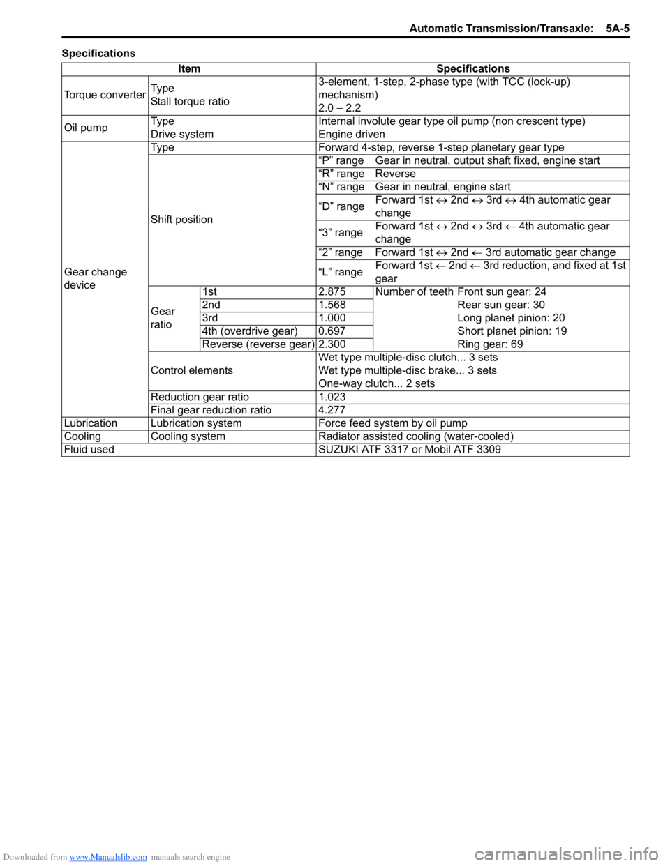
SpecificationsItem Specifications
Torque converter Ty p e
Stall torque ratio 3-element, 1-step, 2-phase type (with TCC (lock-up)
mechanism)
2.0 – 2.2
Oil pump Ty p e
Drive system Internal involute gear type oil pump (non crescent type)
Engine driven
Gear change
device Type Forward 4-step, reverse 1-step planetary gear type
Shift position
“P” range Gear in neutral, output shaft fixed, engine start
“R” range Reverse
“N” range Gear in neutral, engine start
“D” range
Forward 1st
↔ 2nd ↔ 3rd ↔ 4th automatic gear
change
“3” range Forward 1st
↔ 2nd ↔ 3rd ← 4th automatic gear
change
“2” range Forward 1st ↔ 2nd ← 3rd automatic gear change
“L” range Forward 1st
← 2nd ← 3rd reduction, and fixed at 1st
gear
Gear
ratio 1st 2.875 Number of teeth Front sun gear: 24
2nd 1.568 Rear sun gear: 30
3rd 1.000 Long planet pinion: 20
4th (overdrive gear) 0.697 Short planet pinion: 19
Reverse (reverse gear) 2.300 Ring gear: 69
Control elements Wet type multiple-disc clutch... 3 sets
Wet type multiple-d
isc brake... 3 sets
One-way clutch... 2 sets
Reduction gear ratio 1.023
Final gear reduction ratio 4.277
Lubrication Lubrication system Force feed system by oil pump
Cooling Cooling system Radiator assisted cooling (water-cooled)
Fluid used SUZUKI ATF 3317 or Mobil ATF 3309
Page 940 of 1496
Downloaded from www.Manualslib.com manuals search engine 7A-4 Heater and Ventilation:
Repair Instructions
HVAC Unit ComponentsS7RS0B7106001
For manual type A/C, refer to “HVAC Unit Components
in Section 7B”.
For automatic type A/C, refer to “HVAC Unit
Components in Section 7B”.
HVAC Unit Removal and InstallationS7RS0B7106002
Removal
1) Disconnect negative (–) cable from battery.
2) Disable air bag system referring to “Disabling Air Bag System in Section 8B”.
3) Remove cowl top panel from vehicle body referring to “Cowl Top Components in Section 9K”.
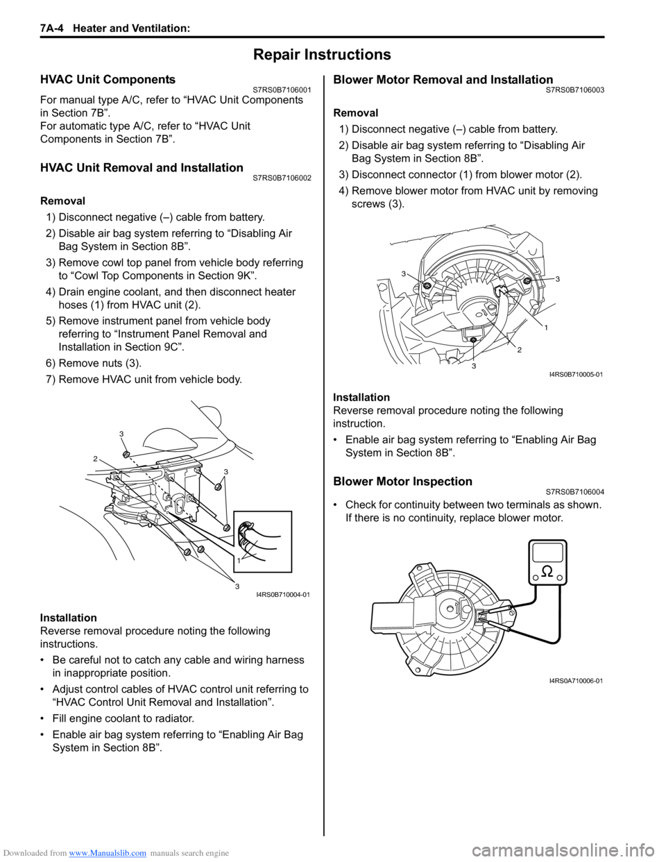
4) Drain engine coolant, and then disconnect heater hoses (1) from HVAC unit (2).
5) Remove instrument panel from vehicle body referring to “Instrument Panel Removal and
Installation in Section 9C”.
6) Remove nuts (3).
7) Remove HVAC unit from vehicle body.
Installation
Reverse removal procedure noting the following
instructions.
• Be careful not to catch any cable and wiring harness in inappropriate position.
• Adjust control cables of HVAC control unit referring to “HVAC Control Unit Remo val and Installation”.
• Fill engine coolant to radiator.
• Enable air bag system referring to “Enabling Air Bag System in Section 8B”.
Blower Motor Removal and InstallationS7RS0B7106003
Removal
1) Disconnect negative (–) cable from battery.
2) Disable air bag system referring to “Disabling Air Bag System in Section 8B”.
3) Disconnect connector (1) from blower motor (2).
4) Remove blower motor from HVAC unit by removing screws (3).
Installation
Reverse removal procedure noting the following
instruction.
• Enable air bag system referring to “Enabling Air Bag System in Section 8B”.
Blower Motor InspectionS7RS0B7106004
• Check for continuity between two terminals as shown. If there is no continuity, replace blower motor.
3
2
3
1
3I4RS0B710004-01
3
1
2
3
3
I4RS0B710005-01
I4RS0A710006-01
Page 952 of 1496
Downloaded from www.Manualslib.com manuals search engine 7B-4 Air Conditioning System: Manual Type
Sub-Cool A/C System DescriptionS7RS0B7211003
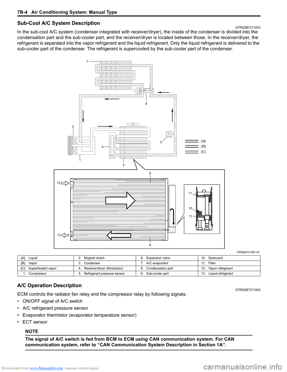
In the sub-cool A/C system (condenser integrated with receiver/dryer), the inside of the condenser is divided into the
condensation part and the sub-cooler part, and the receiver/dryer is located between those. In the receiver/dryer, the
refrigerant is separated into the vapor refrigerant and the liqui d refrigerant. Only the liquid refrigerant is delivered to the
sub-cooler part of the condenser. The refrigerant is supercooled by the sub-cooler part of the condenser.
A/C Operation DescriptionS7RS0B7211004
ECM controls the radiator fan relay and the compressor relay by following signals.
• ON/OFF signal of A/C switch
• A/C refrigerant pressure sensor
• Evaporator thermistor (evaporator temperature sensor)
• ECT sensor
NOTE
The signal of A/C swit ch is fed from BCM to ECM usin g CAN communication system. For CAN
communication system, refer to “CAN Communication System Description in Section 1A”.
I7RS0A721001-01
[A]: Liquid 2. Magnet clutch 6. Expansion valve10. Desiccant
[B]: Vapor 3. Condenser 7. A/C evaporator11. Filter
[C]: Superheated vapor 4. Receiver/dryer (Modulator) 8. Condensation part12. Vapor refrigerant
1. Compressor 5. Refrigerant pressure sensor 9. Sub-cooler part 13. Liquid refrigerant
Page 954 of 1496
Downloaded from www.Manualslib.com manuals search engine 7B-6 Air Conditioning System: Manual Type
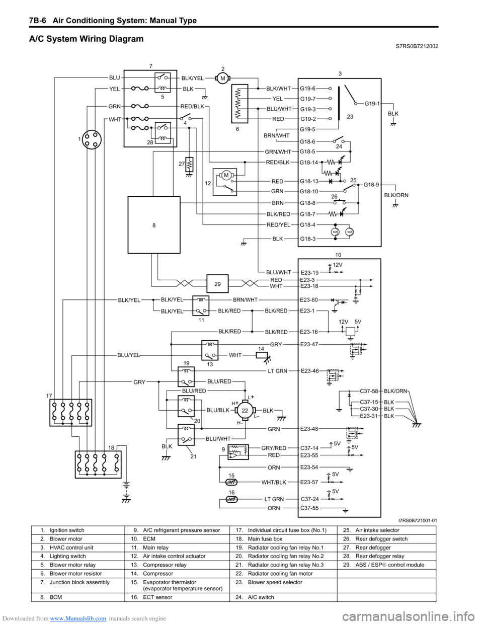
A/C System Wiring DiagramS7RS0B7212002
BLK/REDBLK/RED
BLK/YELBLK/YEL
BLK/YEL
BRN/WHT
12V5V
5V 5V
5V11
E23-1
E23-60
BLK/REDBLK/REDE23-16
E23-57WHT/BLK
9
13
E23-55C37-14GRY/REDRED
BLK
ORN
E23-47 GRY
WHTBLU/YEL
RED/BLK
14 3
1
15
5
7
BLK
2
M
12VBLU/WHTE23-19
C37-24
C37-55ORN
5V
LT GRN16
G18-3
G18-4
G18-7
G18-8
G18-10
G18-13
G18-5
G18-6
G19-5
G19-2
G19-3
G19-7
G19-6
G19-1
G18-9
G18-14
BLK/WHT
YEL
BLU/WHT
RED
BRN/WHT
GRN/WHT
RED/BLK
RED
GRN
BRN
BLK/RED
RED/YEL
BLK
BLK/YEL
BLK/ORN
4
6
12
10
M
E23-54
REDWHTE23-3E23-18
17 18
LT GRNE23-46
L+
L–
H–
H
+
BLU/RED
BLK
BLU/WHTBLK
BLU/BLK
20
GRN
GRY
E23-48
19
21
22
BLU/REDC37-58
C37-15 C37-30
BLK/ORN
BLKBLKE23-31 BLK
BLU
YEL
GRN
WHT
23
24
26 25
28
27
8
29
I7RS0B721001-01
1. Ignition switch
9. A/C refrigerant pressure sensor 17. I ndividual circuit fuse box (No.1) 25. Air intake selector
2. Blower motor 10. ECM 18. Main fuse box 26. Rear defogger switch
3. HVAC control unit 11. Main relay 19. Radiator cooling fan relay No.1 27. Rear defogger
4. Lighting switch 12. Air intake control actuator 20. Radiator cooling fan relay No.2 28. Rear defogger relay
5. Blower motor relay 13. Compressor relay 21. Radiator cooling fan relay No.3 29. ABS / ESP ® control module
6. Blower motor resistor 14. Compressor 22. Radiator cooling fan motor
7. Junction block assembly 15. Evaporator thermistor (evaporator temperature sensor)23. Blower speed selector
8. BCM 16. ECT sensor 24. A/C switch
Page 955 of 1496
Downloaded from www.Manualslib.com manuals search engine Air Conditioning System: Manual Type 7B-7
Diagnostic Information and Procedures
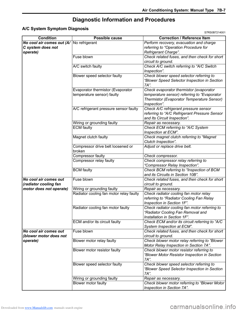
A/C System Symptom DiagnosisS7RS0B7214001
ConditionPossible cause Correction / Reference Item
No cool air comes out (A/
C system does not
operate) No refrigerant
Perform recovery, evacuation and charge
referring to “Operation Procedure for
Refrigerant Charge”.
Fuse blown Check related fuses, and then check for short
circuit to ground.
A/C switch faulty Check A/C switch referring to “A/C Switch
Inspection”.
Blower speed selector faulty Check blower speed selector referring to
“Blower Speed Selector Inspection in Section
7A”.
Evaporator thermistor (Evaporator
temperature sensor) faulty Check evaporator thermistor (evaporator
temperature sensor) referring to “Evaporator
Thermistor (Evaporator Temperature Sensor)
Inspection”.
A/C refrigerant pressure sensor faulty Check A/C refrigerant pressure sensor
referring to “A/C Refrigerant Pressure Sensor
and Its Circuit Inspection”.
Wiring or grounding faulty Repair as necessary.
ECM faulty Check ECM referring to “A/C System
Inspection at ECM”.
Magnet clutch faulty Check magnet clutch referring to “Magnet
Clutch Inspection”.
Compressor drive belt loosened or
broken Adjust or replace drive belt.
Compressor faulty Check compressor.
Compressor relay faulty Check compressor relay referring to
“Compressor Relay Inspection”.
BCM faulty Check BCM referring to “Inspection of BCM
and its Circuits in Section 10B”.
No cool air comes out
(radiator cooling fan
motor does not operate) Fuse blown
Check related fuses, and then check for short
circuit to ground.
Wiring or grounding faulty Repair as necessary.
Radiator cooling fan motor relay faulty Check radiator cooling fan motor relay
referring to “Radiator Cooling Fan Relay
Inspection in Section 1F”.
Radiator cooling fan motor faulty Check radiator cooling fan motor referring to
“Radiator Cooling Fan Removal and
Installation in Section 1F”.
ECM and/or its circuit faulty Check ECM and/or its circuit referring to “A/C
System Inspection at ECM”.
No cool air comes out
(blower motor does not
operate) Fuse blown
Check related fuses, and then check for short
circuit to ground.
Blower motor relay faulty Check blower motor relay referring to “Blower
Motor Relay Inspection in Section 7A”.
Blower motor resistor faulty Check blower motor resistor referring to
“Blower Motor Resistor Inspection in Section
7A”.
Blower speed selector faulty Check blower speed selector referring to
“Blower Speed Selector Inspection in Section
7A”.
Wiring or grounding faulty Repair as necessary.
Blower motor faulty Check blower motor referring to “Blower Motor
Inspection in Section 7A”.
Page 958 of 1496

Downloaded from www.Manualslib.com manuals search engine 7B-10 Air Conditioning System: Manual Type
Abnormal Noise from Tension Pulley
Abnormal Noise from A/C Evaporator
Abnormal Noise from Blower Motor
A/C System Performance InspectionS7RS0B7214003
1) Confirm that vehicle and environmental conditions are as follows.
• Vehicle is put indoors.
• Ambient temperature is within 25 – 35 °C (77 – 95
° F).
• Relative humidity is within 30 – 70%.
• There is no wind indoors.
• HVAC unit is normal.
• Blower motor is normal.
• There is no air leakage from air ducts.
• Condenser fins are clean.
• Air filter in HVAC unit is not clogged with dirt and
dust.
• Battery voltage is about 12 V.
• Radiator cooling fan operates normally.
2) Make sure that high pressure valve (1) and low pressure valve (2) of manifold gauge are firmly
closed.
3) Connect high pressure charging hose (3) to high pressure service valve (5) on vehicle and low
pressure charging hose (4) to low pressure service
valve (6).
4) Bleed the air in charging hoses (3) and (4) by loosening their nuts respectively utilizing the
refrigerant pressure. When a hissing sound is heard,
immediately tighten nut.
CAUTION!
Do not connect high and low pressure
charging hoses in reverse.
Condition Possible cause Correction / Reference Item
Clattering noise is heard
from pulley Worn or damaged bearing
Replace tension pulley.
Pulley cranks upon
contact Cracked or loose bracket
Replace or retighten bracket.
ConditionPossible cause Correction / Reference Item
Whistling sound is heard
from A/C evaporator Depending on the combination of the
interior / exterior temperatures, engine
rpm and refrigerant pressure, the
refrigerant flowing out of the expansion
valve may, under certain conditions,
make a whistling sound At times, slightly decrea
sing refrigerant volume
may stop this noise.
Inspect expansion valve and replace if faulty.
Condition Possible cause Correction / Reference Item
Blower motor emits a
chirping sound in
proportion to its speed of
rotation Worn or damaged motor brushes or
commutator
Replace blower motor.
Fluttering noise or large
droning noise is heard
from blower motor Leaves or other debris introduced from
fresh air inlet to blower motor
Remove debris and make sure that the screen
at fresh air inlet is intact.
53
2
1
4 6
I4RS0A720006-01
Page 960 of 1496
Downloaded from www.Manualslib.com manuals search engine 7B-12 Air Conditioning System: Manual Type
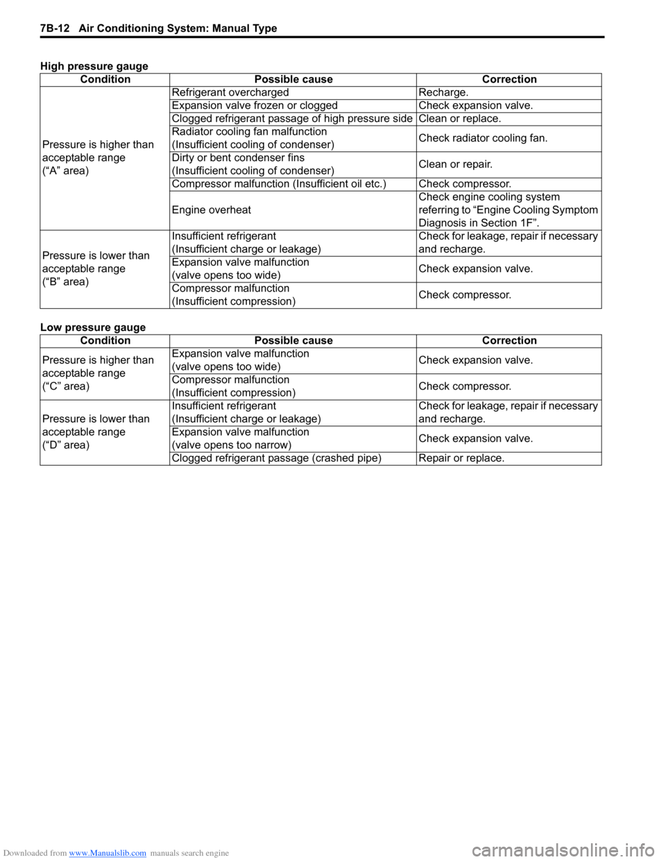
High pressure gauge
Low pressure gaugeCondition Possible cause Correction
Pressure is higher than
acceptable range
(“A” area) Refrigerant overcharged Recharge.
Expansion valve frozen or clogged Check expansion valve.
Clogged refrigerant passage of high pressure side Clean or replace.
Radiator cooling fan malfunction
(Insufficient cooling of condenser)
Check radiator cooling fan.
Dirty or bent condenser fins
(Insufficient cooling of condenser) Clean or repair.
Compressor malfunction (Insuffi cient oil etc.) Check compressor.
Engine overheat Check engine cooling system
referring to “Engin
e Cooling Symptom
Diagnosis in Section 1F”.
Pressure is lower than
acceptable range
(“B” area) Insufficient refrigerant
(Insufficient charge or leakage)
Check for leakage, repair if necessary
and recharge.
Expansion valve malfunction
(valve opens too wide) Check expansion valve.
Compressor malfunction
(Insufficient compression) Check compressor.
Condition Possible cause Correction
Pressure is higher than
acceptable range
(“C” area) Expansion valve malfunction
(valve opens too wide)
Check expansion valve.
Compressor malfunction
(Insufficient compression) Check compressor.
Pressure is lower than
acceptable range
(“D” area) Insufficient refrigerant
(Insufficient charge or leakage)
Check for leakage, repair if necessary
and recharge.
Expansion valve malfunction
(valve opens too narrow) Check expansion valve.
Clogged refrigerant passage (crashed pipe) Repair or replace.