2007 SUZUKI SWIFT adjustment
[x] Cancel search: adjustmentPage 820 of 1496

Downloaded from www.Manualslib.com manuals search engine 5B-6 Manual Transmission/Transaxle:
Gear Shift Control Lever and Cable Removal
and Installation
S7RS0B5206004
Removal1) Remove console box.
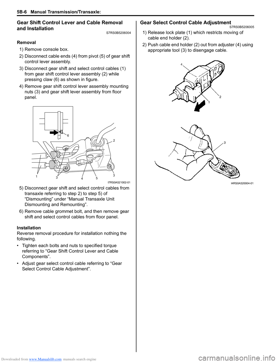
2) Disconnect cable ends (4) from pivot (5) of gear shift control lever assembly.
3) Disconnect gear shift and select control cables (1) from gear shift control lever assembly (2) while
pressing claw (6) as shown in figure.
4) Remove gear shift control lever assembly mounting nuts (3) and gear shift lever assembly from floor
panel.
5) Disconnect gear shift and select control cables from transaxle referring to step 2) to step 5) of
“Dismounting” under “Manual Transaxle Unit
Dismounting and Remounting”.
6) Remove cable grommet bolt, and then remove gear shift and select control cables from floor panel.
Installation
Reverse removal procedure for installation nothing the
following.
• Tighten each bolts and nuts to specified torque referring to “Gear Shift Control Lever and Cable
Components”.
• Adjust gear select control cable referring to “Gear Select Control Cable Adjustment”.
Gear Select Control Cable AdjustmentS7RS0B5206005
1) Release lock plate (1) which restricts moving of cable end holder (2).
2) Push cable end holder (2) out from adjuster (4) using appropriate tool (3) to disengage cable.
35
4
2
31
6
I7RS0A521002-01I4RS0A520004-01
Page 856 of 1496

Downloaded from www.Manualslib.com manuals search engine 5C-4 Clutch:
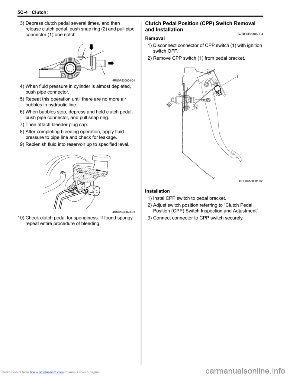
3) Depress clutch pedal several times, and then release clutch pedal, push snap ring (2) and pull pipe
connector (1) one notch.
4) When fluid pressure in cylinder is almost depleted, push pipe connector.
5) Repeat this operation until there are no more air bubbles in hydraulic line.
6) When bubbles stop, depress and hold clutch pedal, push pipe connector, and pull snap ring.
7) Then attach bleeder plug cap.
8) After completing bleeding operation, apply fluid pressure to pipe line and check for leakage.
9) Replenish fluid into reserv oir up to specified level.
10) Check clutch pedal for sponginess. If found spongy, repeat entire procedure of bleeding.Clutch Pedal Position (CPP) Switch Removal
and Installation
S7RS0B5306004
Removal
1) Disconnect connector of C PP switch (1) with ignition
switch OFF.
2) Remove CPP switch (1 ) from pedal bracket.
Installation 1) Instal CPP switch to pedal bracket.
2) Adjust switch position re ferring to “Clutch Pedal
Position (CPP) Switch Inspection and Adjustment”.
3) Connect connector to CPP switch securely.
2
1
I4RS0A530004-01
I4RS0A530023-01
1
I6RS0C530001-02
Page 857 of 1496

Downloaded from www.Manualslib.com manuals search engine Clutch: 5C-5
Clutch Pedal Position (CPP) Switch Inspection
and Adjustment
S7RS0B5306005
Inspection
Check for resistance between terminals under each
condition below. If check result is not satisfactory,
replace.
CPP switch resistance
When switch shaft is pushed (1): Continuity
When switch shaft is free (2): No continuityAdjustment
With clutch pedal depressed,
adjust switch (1) position
so that clearance between end of thread and clutch
pedal arm is within specification, and then tighten lock
nut to specified torque.
Clearance between end of thread and clutch pedal
arm
“a”: 3.5 – 4.0 mm (0.14 – 0.16 in.)
Tightening torque
CPP switch lock nut (a): 7.5 N·m (0.75 kgf-m, 5.5 lb-
ft)
Clutch Fluid Pipe and Hose ComponentsS7RS0B5306006
I5JB0A530006-01
(a)
1
“a”
I6RS0C530002-01
6
1
5
2 5
4(a)
3
I6RS0C530003-01
1. Master cylinder
: Apply grease 99000-25100 to push rod end. 5. Clamp
2. Pipe 6. Clutch reservoir hose
3. Operating cylinder : Apply grease 99000-25100 to rod tip. : 23 N
⋅m (2.3 kgf-m, 17.0 lb-ft)
4. Operating cylinder bolt
Page 871 of 1496

Downloaded from www.Manualslib.com manuals search engine Steering General Diagnosis: 6A-2
Diagnostic Information and Procedures
Steering Symptom DiagnosisS7RS0B6104001
ConditionPossible cause Correction / Reference Item
Hard steering Tire not adequately inflated Inflate tires to proper pressure.
Malfunction of power steering system Check and correct.
Bind in tie-rod end ball studs or lower
ball joints Replace tie-rod end or front suspension arm.
Disturbed front wheel alignment Check and adjust front wheel alignment.
Bind in steering column Repair or replace steering column.
Rack and pinion adjustment Check and adjustment rack and pinion torque.
Too much play in steering Wheel bearings worn Replace wheel bearing.
Loose steering gear case bolts Tighten gear case bolts.
Faulty steering gear case assembly Replace steering gear case assembly.
Worn steering shaft joints Replace joint.
Worn tie-rod ends or tie-rod inside ball
joints Replace tie-rod end or tie-rod.
Worn lower ball joints Replace front suspension control arm.
Rack and pinion adjustment Check and adjustment rack and pinion torque.
Poor return ability Bind in tie-rod end ball studs Replace tie-rod end.
Bind in ball joints Replace front suspension control arm.
Bind in steering column Repair or replace steering column.
Disturbed front end alignment Check and adjust front end alignment.
Faulty steering gear case assembly Replace steering gear case assembly.
Tires not adequately inflated Adjust tire pressure.
Rack and pinion adjustment Check and adjustment rack and pinion torque.
Rack and pinion noise
(Rattle or chuckle) Loose steering gear case bolts
Tighten steering gear case bolts.
Rack and pinion adjustment Check and adjustment rack and pinion torque.
Faulty steering gear case assembly Replace steering gear case assembly.
Broken or other wise damaged wheel
bearing(s) Replace wheel bearing(s).
Wander or poor steering
stability Mismatched or uneven tires
Replace or inflate tires to proper pressure.
Loosen ball joints and tie-rod ends Replace suspension control arm or tie-rod end.
Faulty struts or mountings Replace strut or repair mounting.
Loose stabilizer bar Tighten or replace stabilizer bar or bush.
Broken or sagging springs Replace spring.
Rack and pinion adjustment Check and adjustment rack and pinion torque.
Disturbed front wheel alignment Check and adjust front wheel alignment.
Faulty steering gear case assembly Replace steering gear case assembly.
Erratic steering when
braking Worn wheel bearing(s)
Replace wheel bearing(s).
Broken or sagging spring(s) Replace coil spring(s).
Wheel tires are inflated unequally Inflate tires to proper pressure.
Disturbed front wheel alignment Check and adjust front wheel alignment.
Brakes not working in unison Check and repair brake system.
Leaking caliper Repair or replace caliper.
Warped discs Replace brake disc.
Badly worn brake pads Replace brake pads.
Page 923 of 1496

Downloaded from www.Manualslib.com manuals search engine Power Assisted Steering System: 6C-41
Tie-Rod End Boot On-Vehicle InspectionS7RS0B6306002
Check boot for crack and damage.
If any defect is found, replace it with a new one.
Tie-Rod End Removal and InstallationS7RS0B6306003
Removal1) Hoist vehicle, and then remove wheel referring to “Wheel Removal and Installation in Section 2D”.
2) Remove split pin (2) and tie-rod end nut (1) from steering knuckle.
3) Disconnect tie-rod end (1) from knuckle (2) using puller (3). 4) For ease of adjustment after installation, make
marking (1) of tie-rod end lock nut (2) position on tie-
rod end thread. Then, loosen lock nut and remove
tie-rod end (3) from tie-rod (4).
Installation 1) Install tie-rod end lock nut (1) and tie-rod end (2) to tie-rod (3). Align lock nut with mark (4) on tie-rod
thread.
9. Tie-rod end nut 20. Gear rack side No.2 bracket : 9.5 N⋅m (0.95 kgf-m, 7.0 lb-ft)
10. Steering gear case mounting No.1 bolt 21. Steering gear case mounting No.2 bolt : Do not reuse.
11. Steering gear case grommet 22. Clip
I3RM0A630024-01
21
I7RS0A630016-01
2 1
3
I4RS0A630040-01
I4RS0A630041-01
I4RS0A630042-01
Page 924 of 1496

Downloaded from www.Manualslib.com manuals search engine 6C-42 Power Assisted Steering System:
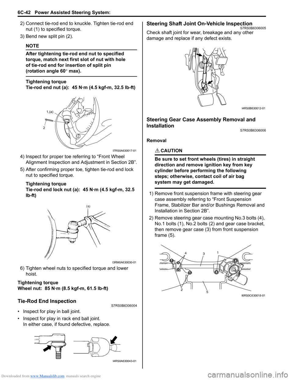
2) Connect tie-rod end to knuckle. Tighten tie-rod end nut (1) to spec ified torque.
3) Bend new split pin (2).
NOTE
After tightening tie-rod end nut to specified
torque, match next first slot of nut with hole
of tie-rod end for insertion of split pin
(rotation angle 60 ° max).
Tightening torque
Tie-rod end nut (a): 45 N·m (4.5 kgf-m, 32.5 lb-ft)
4) Inspect for proper toe re ferring to “Front Wheel
Alignment Inspection and Adjustment in Section 2B”.
5) After confirming proper toe, tighten tie-rod end lock nut to specified torque.
Tightening torque
Tie-rod end lock nut (a): 45 N·m (4.5 kgf-m, 32.5
lb-ft)
6) Tighten wheel nuts to specified torque and lower hoist.
Tightening torque
Wheel nut: 85 N·m (8.5 kgf-m, 61.5 lb-ft)
Tie-Rod End InspectionS7RS0B6306004
• Inspect for play in ball joint.
• Inspect for play in rack end ball joint. In either case, if found defective, replace.
Steering Shaft Joint On-Vehicle InspectionS7RS0B6306005
Check shaft joint for wear, breakage and any other
damage and replace if any defect exists.
Steering Gear Case Assembly Removal and
Installation
S7RS0B6306006
Removal
CAUTION!
Be sure to set front wheels (tires) in straight
direction and remove ignition key from key
cylinder before performing the following
steps; otherwise, contact coil of air bag
system may get damaged.
1) Remove front suspension frame with steering gear case assembly referrin g to “Front Suspension
Frame, Stabilizer Bar and/ or Bushings Removal and
Installation in Section 2B”.
2) Remove steering gear case mounting No.3 bolts (4), No.1 bolts (1), No.2 bolts (2) and gear case bracket,
then remove gear case (3) from front suspension
frame (5).
2 1,(a)
I7RS0A630017-01
I3RM0A630030-01
I4RS0A630043-01
I4RS0B630012-01
25
3
14
I6RS0C630018-01
Page 925 of 1496

Downloaded from www.Manualslib.com manuals search engine Power Assisted Steering System: 6C-43
Installation1) Mount steering gear case (1) to front suspension frame (2) and tighten gear case mounting No.1 bolts
(3), No.2 bolts (4) and No .3 bolts (5) to specified
torque.
Tightening torque
Steering gear case mounting No.1 bolt (a): 55
N·m (5.5 kgf-m, 40.0 lb-ft)
Steering gear case mounting No.2 bolt (b): 55
N·m (5.5 kgf-m, 40.0 lb-ft)
Steering gear case mounting No.3 bolt (c): 40
N·m (4.0 kgf-m, 29.0 lb-ft)
2) Install earth cable (6) as shown in figure. Tightening torque
Earth cable bolt (d): 4.5 N·m (0.45 kgf-m, 3.5 lb-
ft)
3) Install grommet (1) whose projection (2) orients vehicle forward.
4) Install front suspension frame with steering gear case assembly referring to “Front Suspension
Frame, Stabilizer Bar and/or Bushings Removal and
Installation in Section 2B”.Steering Rack Boot InspectionS7RS0B6306007
Hoist vehicle.
Inspect each boot for tear. A torn boot allows entry of
dust and water which can cause wear to steering rack
and pinion to produce noise as well as rust to result in
malfunction of steering system.
Even if boot tear is small, replace with new one.
Also, check each boot for dent. If there is a dent, keep
boot in most compressed st ate for some seconds to
correct dent.
Boots should be visually inspected for any damage, dent
and tear during every periodical inspection at specified
intervals and whenever vehicle is hoisted for any other
purpose.
Tie-Rod / Rack Boot Removal and InstallationS7RS0B6306008
Removal
1) Remove steering gear case assembly referring to
“Steering Gear Case Assembly Removal and
Installation”.
2) For ease of adjustment after installation, make marking (1) of tie-rod end lock nut position of tie-rod
thread.
3) Loosen tie-rod end lock nut and remove tie-rod end.
4) Remove boot band (2) and clip (1).
5) Remove boot from tie-rod.
F: Vehicle forward
1 2
3, (a) 4, (b)
6, (d)
5, (c)
I6RS0C630019-02
12
F
I6RS0C630020-01
I2RH01630012-01
I4RS0A630044-01
IYSQ01630034-01
Page 927 of 1496

Downloaded from www.Manualslib.com manuals search engine Power Assisted Steering System: 6C-45
8) Install steering gear case assembly referring to “Steering Gear Case Assembly Removal and
Installation”.
Steering Rack Plunger Removal and InstallationS7RS0B6306009
Removal
1) Remove gear case assembly referring to “Steering
Gear Case Assembly Removal and Installation”.
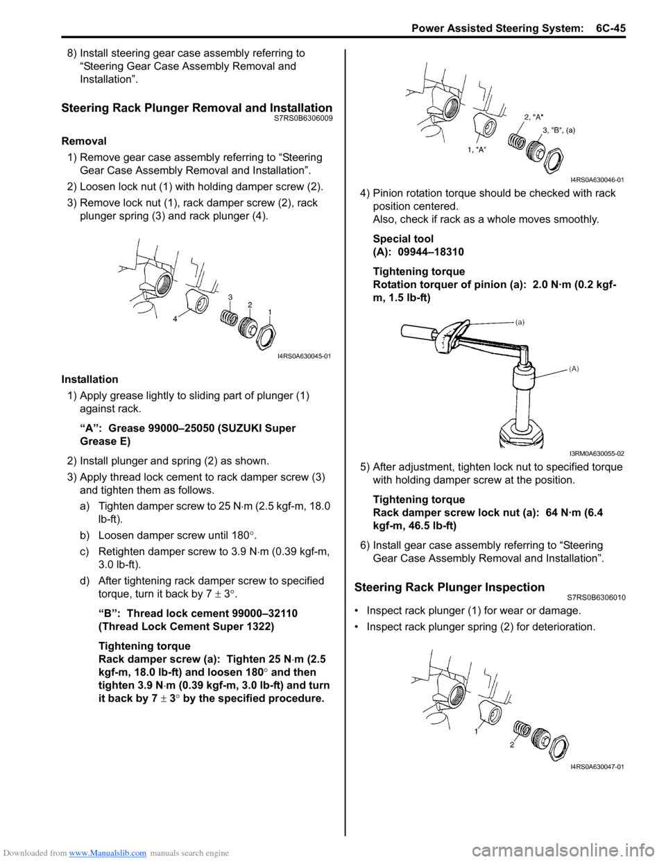
2) Loosen lock nut (1) with holding damper screw (2).
3) Remove lock nut (1), rack damper screw (2), rack plunger spring (3) and rack plunger (4).
Installation 1) Apply grease lightly to sliding part of plunger (1) against rack.
“A”: Grease 99000–25050 (SUZUKI Super
Grease E)
2) Install plunger and spring (2) as shown.
3) Apply thread lock cement to rack damper screw (3)
and tighten them as follows.
a) Tighten damper screw to 25 N ⋅m (2.5 kgf-m, 18.0
lb-ft).
b) Loosen damper screw until 180 °.
c) Retighten damper screw to 3.9 N ⋅m (0.39 kgf-m,
3.0 lb-ft).
d) After tightening rack damper screw to specified torque, turn it back by 7 ± 3°.
“B”: Thread lock cement 99000–32110
(Thread Lock Cement Super 1322)
Tightening torque
Rack damper screw (a): Tighten 25 N ⋅m (2.5
kgf-m, 18.0 lb-ft) and loosen 180° and then
tighten 3.9 N ⋅m (0.39 kgf-m, 3.0 lb-ft) and turn
it back by 7 ± 3° by the specified procedure. 4) Pinion rotation torque should be checked with rack
position centered.
Also, check if rack as a whole moves smoothly.
Special tool
(A): 09944–18310
Tightening torque
Rotation torquer of pinion (a): 2.0 N·m (0.2 kgf-
m, 1.5 lb-ft)
5) After adjustment, tighten lo ck nut to specified torque
with holding damper screw at the position.
Tightening torque
Rack damper screw lock nut (a): 64 N·m (6.4
kgf-m, 46.5 lb-ft)
6) Install gear case assembly referring to “Steering Gear Case Assembly Re moval and Installation”.
Steering Rack Plunger InspectionS7RS0B6306010
• Inspect rack plunger (1) for wear or damage.
• Inspect rack plunger spring (2) for deterioration.
I4RS0A630045-01
I4RS0A630046-01
I3RM0A630055-02
I4RS0A630047-01