2007 SUZUKI SWIFT Ig coil inspection
[x] Cancel search: Ig coil inspectionPage 1077 of 1496
Downloaded from www.Manualslib.com manuals search engine Air Bag System: 8B-39
DTC B1034: Driver Air Bag Initiator Circuit Short to Power CircuitS7RS0B8204021
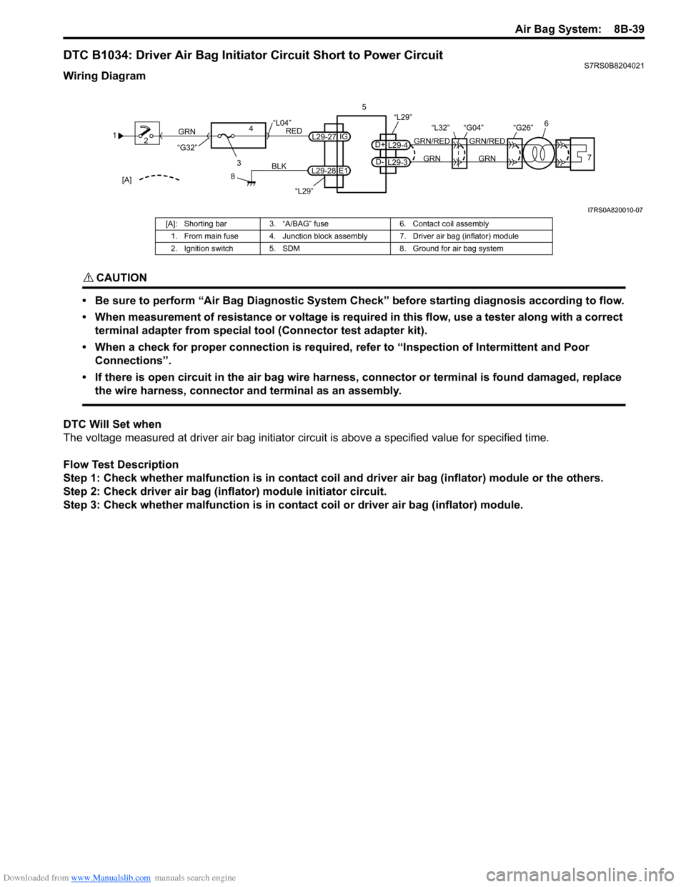
Wiring Diagram
CAUTION!
• Be sure to perform “Air Bag Diagnostic System Check” before starting diagnosis according to flow.
• When measurement of resistance or voltage is required in this flow, use a tester along with a correct terminal adapter from special tool (Connector test adapter kit).
• When a check for proper connection is required, refer to “Inspection of Intermittent and Poor Connections”.
• If there is open circuit in the air bag wire harnes s, connector or terminal is found damaged, replace
the wire harness, connector and terminal as an assembly.
DTC Will Set when
The voltage measured at driver air bag initiator ci rcuit is above a specified value for specified time.
Flow Test Description
Step 1: Check whether malfunction is in contact coil and driver air bag (inflator) module or the others.
Step 2: Check driver air bag (inflator) module initiator circuit.
Step 3: Check whether malfunction is in contact coil or driver air bag (inflator) module.
1 2
3
GRN
RED
8
BLK
L29-27
L29-28 IG
E1
4
“L29”
“L04”
“G32”
“L29”
L29-4
D+
L29-3
D-GRN
GRN/RED
GRN
GRN/RED 6
57
“G26”
“L32” “G04”
[A]
I7RS0A820010-07
[A]: Shorting bar 3. “A/BAG” fuse 6. Contact coil assembly
1. From main fuse 4. Junction block assembly 7. Driver air bag (inflator) module
2. Ignition switch 5. SDM 8. Ground for air bag system
Page 1081 of 1496
Downloaded from www.Manualslib.com manuals search engine Air Bag System: 8B-43
NOTE
Upon completion of inspection and repair work, perform the following items.
• Reconnect all air bag system components and ensure all components are properly mounted.
• Clear DTCs referring to “DTC Clearance”, if any.
• Repeat “Air Bag Diagnostic System Check” to confirm that the trouble has been corrected.
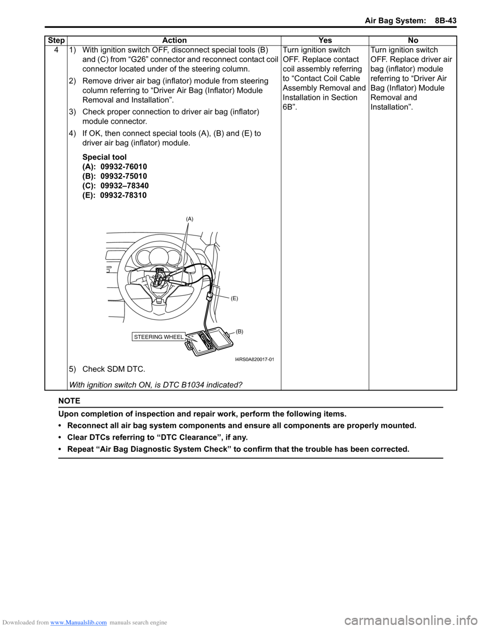
4 1) With ignition switch OFF, disconnect special tools (B) and (C) from “G26” connector and reconnect contact coil
connector located under of the steering column.
2) Remove driver air bag (inflator) module from steering column referring to “Driver Air Bag (Inflator) Module
Removal and Installation”.
3) Check proper connection to driver air bag (inflator) module connector.
4) If OK, then connect special tools (A), (B) and (E) to driver air bag (inflator) module.
Special tool
(A): 09932-76010
(B): 09932-75010
(C): 09932–78340
(E): 09932-78310
5) Check SDM DTC.
With ignition switch ON , is DTC B1034 indicated? Turn ignition switch
OFF. Replace contact
coil assembly referring
to “Contact Coil Cable
Assembly Removal and
Installation in Section
6B”.
Turn ignition switch
OFF. Replace driver air
bag (inflator) module
referring to “Driver Air
Bag (Inflator) Module
Removal and
Installation”.
Step Action Yes No
STEERING WHEEL(B)
(E)
(A)
I4RS0A820017-01
Page 1134 of 1496
Downloaded from www.Manualslib.com manuals search engine 8B-96 Air Bag System:
Repair and Inspection Required after AccidentS7RS0B8204049
CAUTION!
• All air bag system components, including the electrical harness (component
mounting points), must be inspected after
an accident. If any components are
damaged or bent, they must be replaced
even if air bag system activation did not
occur.
• Never use air bag system parts from another vehicle.
• Do not attempt to service the parts below. Service of these parts is by replacement
only.
– Driver / Passenger air bag (inflator) modules
– Driver / Passenger side-air bag (inflator) modules
– Driver / Passenger side curtain-air bag (inflator) modules
– Driver / Passenger seat belt pretensioners
–Forward-sensor
– Driver / Passenger side-sensors
–SDM
– Contact coil and combination switch assembly
– Air bag wire harness in main harness, instrument panel harness and floor
harness.
• Proper operation of the sensors and air bag system requires that any repairs to the
vehicle structure return it to its original
production configuration.
CAUTION!
After detecting one time of such collision as
to meet deployment conditions, the SDM
must not be used.
Refer to “Air Bag Diagnostic System Check”
when checking the SDM.
Accident with Deployment / Activation – Component
Replacement
When driver and passenger air bags are deployed, the
following components must be replaced.
• Driver and passenger air bag (inflator) modules
• Driver and passenger seat belt pretensioners
• SDM after detecting such collision as to meet
deployment conditions
• Forward-sensor
• Instrument panel When side-air bag and side curtain-air bag are deployed,
the following components must be replaced.
• Deployed side-air bag (inflator) module
• Deployed side curtain-air bag (inflator) module
• Side-sensor
•SDM
Accident with or without Deployment / Activation –
Component Inspections
Certain air bag and restraint system components must
be inspected after any crash, whether the air bag system
activated or not. If any faul
ty condition is found in the
following checks, replace faulty part.
Those components are:
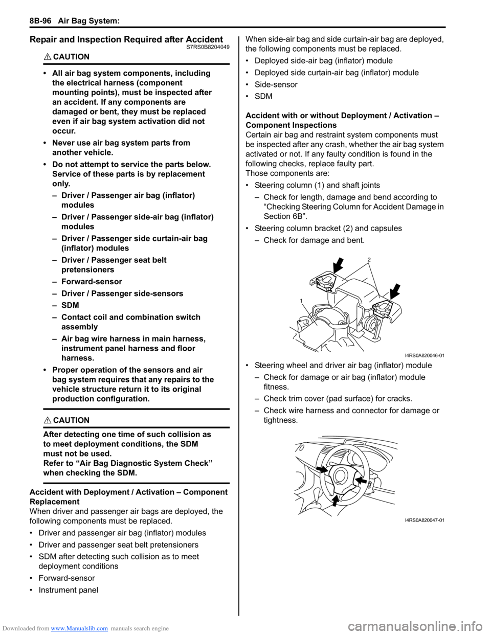
• Steering column (1) and shaft joints
– Check for length, damage and bend according to “Checking Steering Column for Accident Damage in
Section 6B”.
• Steering column bracket (2) and capsules – Check for damage and bent.
• Steering wheel and driver air bag (inflator) module – Check for damage or air bag (inflator) module fitness.
– Check trim cover (pad surface) for cracks.
– Check wire harness and connector for damage or tightness.
2
1
I4RS0A820046-01
I4RS0A820047-01
Page 1135 of 1496
Downloaded from www.Manualslib.com manuals search engine Air Bag System: 8B-97
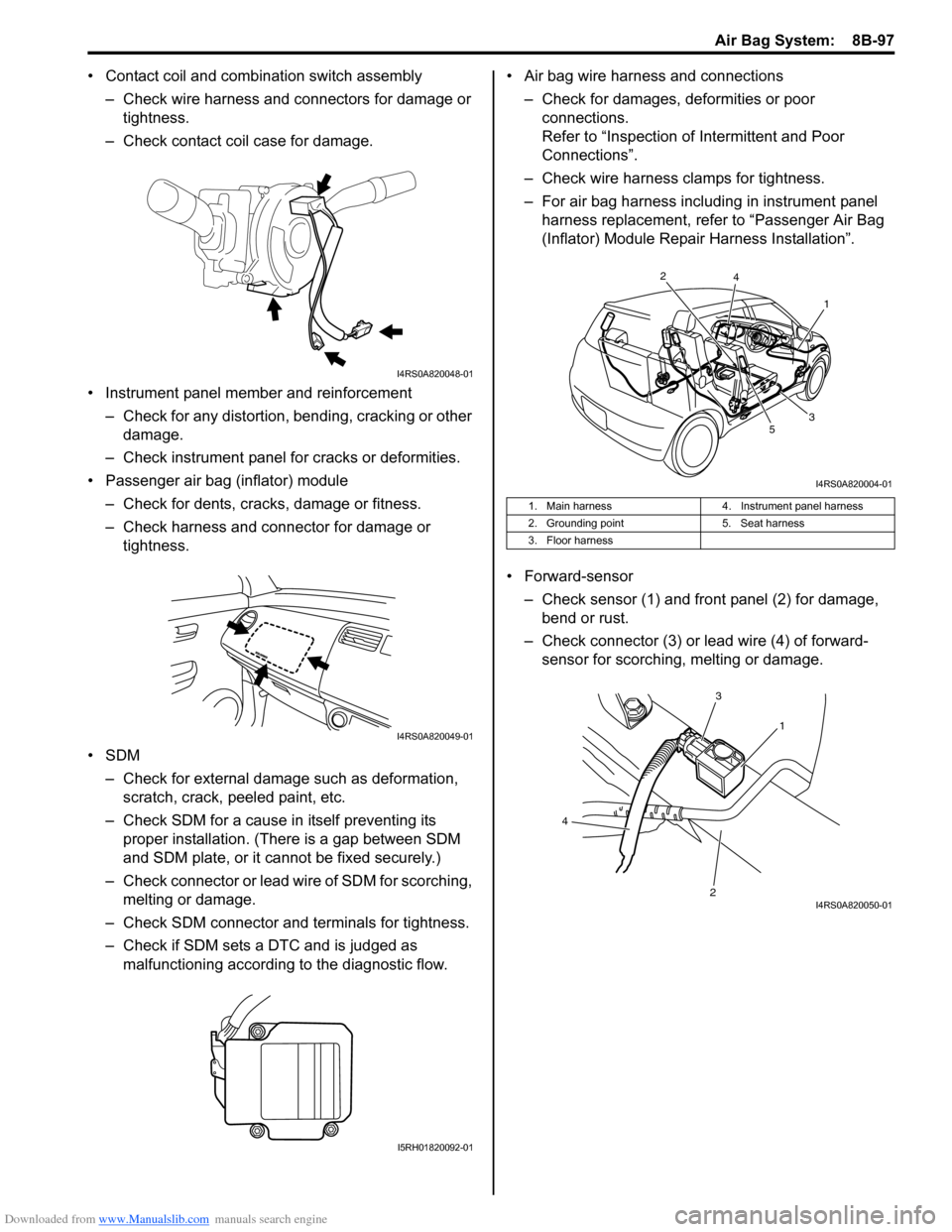
• Contact coil and combination switch assembly
– Check wire harness and connectors for damage or tightness.
– Check contact coil case for damage.
• Instrument panel member and reinforcement – Check for any distortion, bending, cracking or other damage.
– Check instrument panel fo r cracks or deformities.
• Passenger air bag (inflator) module
– Check for dents, cracks, damage or fitness.
– Check harness and connector for damage or tightness.
•SDM – Check for external damage such as deformation, scratch, crack, peeled paint, etc.
– Check SDM for a cause in itself preventing its proper installation. (There is a gap between SDM
and SDM plate, or it cannot be fixed securely.)
– Check connector or lead wire of SDM for scorching, melting or damage.
– Check SDM connector and terminals for tightness.
– Check if SDM sets a DTC and is judged as malfunctioning according to the diagnostic flow. • Air bag wire harness and connections
– Check for damages, deformities or poor connections.
Refer to “Inspection of Intermittent and Poor
Connections”.
– Check wire harness clamps for tightness.
– For air bag harness including in instrument panel harness replacement, refer to “Passenger Air Bag
(Inflator) Module Repair Harness Installation”.
• Forward-sensor – Check sensor (1) and front panel (2) for damage, bend or rust.
– Check connector (3) or lead wire (4) of forward- sensor for scorching, melting or damage.
I4RS0A820048-01
I4RS0A820049-01
I5RH01820092-01
1. Main harness 4. Instrument panel harness
2. Grounding point 5. Seat harness
3. Floor harness
1
2
3
4
5
I4RS0A820004-01
1
3
2
4
I4RS0A820050-01
Page 1308 of 1496
Downloaded from www.Manualslib.com manuals search engine 9C-13 Instrumentation / Driver Info. / Horn:
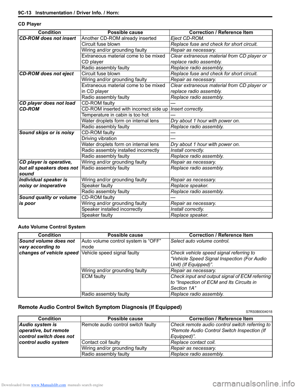
CD Player
Auto Volume Control System
Remote Audio Control Switch Symptom Diagnosis (If Equipped)S7RS0B9304018
ConditionPossible cause Correction / Reference Item
CD-ROM does not insert Another CD-ROM already inserted Eject CD-ROM.
Circuit fuse blown Replace fuse and check for short circuit.
Wiring and/or grounding faulty Repair as necessary.
Extraneous material come to be mixed
CD player Clear extraneous material from CD player or
replace radio assembly.
Radio assembly faulty Replace radio assembly.
CD-ROM does not eject Circuit fuse blown Replace fuse and check for short circuit.
Wiring and/or grounding faulty Repair as necessary.
Extraneous material come to be mixed
in CD player Clear extraneous material from CD player or
replace radio assembly.
Radio assembly faulty Replace radio assembly.
CD player does not load
CD-ROM CD-ROM faulty
—
CD-ROM inserted wit h incorrect side upInsert correctly.
Temperature in cabin is too hot —
Water droplets form on internal lens Dry about 1 hour with power on.
Radio assembly faulty Replace radio assembly.
Sound skips or is noisy CD-ROM faulty —
Driving vibration —
Water droplets form on internal lens Dry about 1 hour with power on.
Radio assembly installed incorrectly Install correctly.
Radio assembly faulty Replace radio assembly.
CD player is operative,
but all speakers does not
sound Wiring and/or grounding faulty
Repair as necessary.
Radio assembly faulty Replace radio assembly.
Individual speaker is
noisy or inoperative Wiring and/or grounding faulty
Repair as necessary.
Speaker faulty Replace speaker.
Radio assembly faulty Replace radio assembly.
Sound quality or volume
is poor CD-ROM faulty
—
Wiring and/or grounding faulty Repair as necessary.
Speaker installed incorrectly Install correctly.
Speaker faulty Replace speaker.
ConditionPossible cause Correction / Reference Item
Sound volume does not
vary according to
changes of vehicle speed Auto volume control system is “OFF”
mode
Select auto volume control.
Vehicle speed signal faulty Check vehicle speed signal referring to
“Vehicle Speed Signal Inspection (For Audio
Unit) (If Equipped)”.
Wiring and/or grounding faulty Repair as necessary.
ECM faulty Check input and output signal of ECM referring
to “Inspection of ECM and Its Circuits in
Section 1A”
Radio assembly faulty Replace radio assembly.
ConditionPossible cause Correction / Reference Item
Audio system is
operative, but remote
control switch does not
control audio system Remote audio control switch faulty
Check remote audio control switch referring to
“Remote Audio Control Switch Inspection (If
Equipped)”.
Contact coil faulty Replace contact coil.
Wiring and/or grounding faulty Repair as necessary.
Radio assembly faulty Replace radio assembly.
Page 1317 of 1496
Downloaded from www.Manualslib.com manuals search engine Instrumentation / Driver Info. / Horn: 9C-22
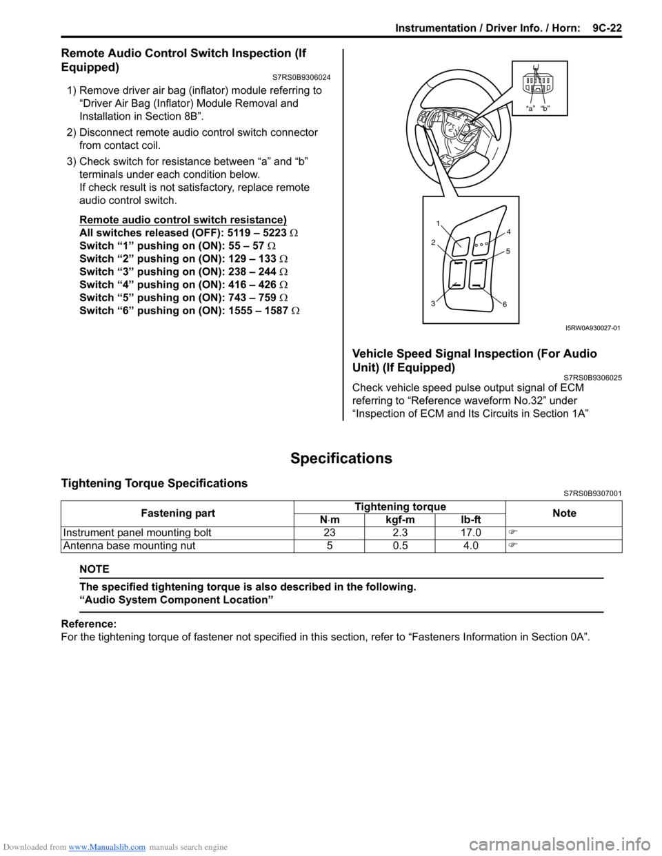
Remote Audio Control Switch Inspection (If
Equipped)
S7RS0B9306024
1) Remove driver air bag (inflator) module referring to
“Driver Air Bag (Inflator) Module Removal and
Installation in Section 8B”.
2) Disconnect remote audio control switch connector
from contact coil.
3) Check switch for resistance between “a” and “b” terminals under each condition below.
If check result is not satisfactory, replace remote
audio control switch.
Remote audio control switch resistance)
All switches released (OFF): 5119 – 5223 Ω
Switch “1” pushing on (ON): 55 – 57 Ω
Switch “2” pushing on (ON): 129 – 133 Ω
Switch “3” pushing on (ON): 238 – 244 Ω
Switch “4” pushing on (ON): 416 – 426 Ω
Switch “5” pushing on (ON): 743 – 759 Ω
Switch “6” pushing on (ON): 1555 – 1587 Ω
Vehicle Speed Signal Inspection (For Audio
Unit) (If Equipped)
S7RS0B9306025
Check vehicle speed pulse output signal of ECM
referring to “Reference waveform No.32” under
“Inspection of ECM and Its Circuits in Section 1A”
Specifications
Tightening Torque SpecificationsS7RS0B9307001
NOTE
The specified tightening torque is also described in the following.
“Audio System Component Location”
Reference:
For the tightening torque of fastener not specified in this section, refer to “Fasteners Information in Section 0A”.
“b”“a”
1
2
3 4
5
6
I5RW0A930027-01
Fastening part Tightening torque
Note
N ⋅mkgf-mlb-ft
Instrument panel mounting bolt 23 2.3 17.0 �)
Antenna base mounting nut 5 0.5 4.0 �)