2007 SUZUKI SWIFT waveform no
[x] Cancel search: waveform noPage 919 of 1496
Downloaded from www.Manualslib.com manuals search engine Power Assisted Steering System: 6C-37
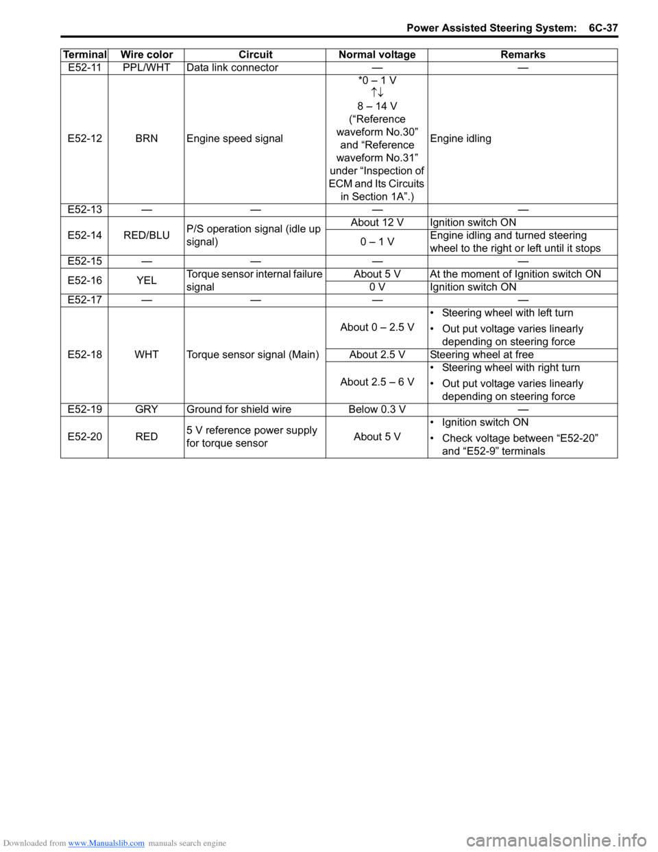
E52-11 PPL/WHT Data link connector——
E52-12 BRN Engine speed signal *0 – 1 V
↑↓
8 – 14 V
(“Reference
waveform No.30” and “Reference
waveform No.31”
under “Inspection of
ECM and Its Circuits in Section 1A”.) Engine idling
E52-13 — —— —
E52-14 RED/BLU P/S operation signal (idle up
signal) About 12 V Ignition switch ON
0 – 1 V Engine idling and turned steering
wheel to the right or left until it stops
E52-15 — —— —
E52-16 YEL Torque sensor internal failure
signal About 5 V At the moment of Ignition switch ON
0 V Ignition switch ON
E52-17 — —— —
E52-18 WHT Torque sensor signal (Main) About 0 – 2.5 V
• Steering wheel with left turn
• Out put voltage varies linearly
depending on steering force
About 2.5 V Steering wheel at free
About 2.5 – 6 V • Steering wheel with right turn
• Out put voltage varies linearly
depending on steering force
E52-19 GRY Ground for shield wire Below 0.3 V—
E52-20 RED 5 V reference power supply
for torque sensor About 5 V• Ignition switch ON
• Check voltage between “E52-20”
and “E52-9” terminals
Terminal Wire color
Circuit Normal voltage Remarks
Page 920 of 1496
Downloaded from www.Manualslib.com manuals search engine 6C-38 Power Assisted Steering System:
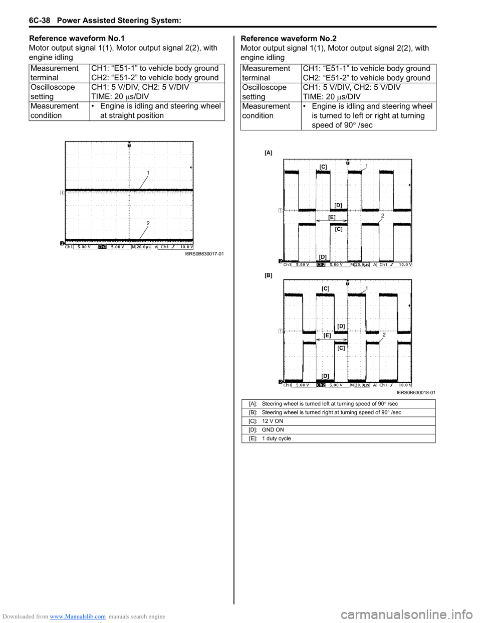
Reference waveform No.1
Motor output signal 1(1), Motor output signal 2(2), with
engine idlingReference waveform No.2
Motor output signal 1(1), Motor output signal 2(2), with
engine idling
Measurement
terminal CH1: “E51-1” to vehicle body ground
CH2: “E51-2” to vehicle body ground
Oscilloscope
setting CH1: 5 V/DIV, CH2: 5 V/DIV
TIME: 20
µs/DIV
Measurement
condition • Engine is idling and steering wheel
at straight position
I6RS0B630017-01
Measurement
terminal CH1: “E51-1” to vehicle body ground
CH2: “E51-2” to vehicle body ground
Oscilloscope
setting CH1: 5 V/DIV, CH2: 5 V/DIV
TIME: 20 µ
s/DIV
Measurement
condition • Engine is idling and steering wheel
is turned to left or right at turning
speed of 90 ° /sec
[A]: Steering wheel is turned left at turning speed of 90 ° /sec
[B]: Steering wheel is turned right at turning speed of 90 ° /sec
[C]: 12 V ON
[D]: GND ON [E]: 1 duty cycle
I6RS0B630018-01
Page 921 of 1496

Downloaded from www.Manualslib.com manuals search engine Power Assisted Steering System: 6C-39
Reference waveform No.3
Motor output signal 1(1), Motor output signal 2(2), with
engine idling
Steering Wheel Play CheckS7RS0B6304024
• Check steering wheel for looseness or rattle by moving it in its shaft direction and lateral direction.
If found defective, repair or replace.
• Check steering wheel for play, holding vehicle in straight forward condition on the ground with engine
stopped.
If steering wheel play is not within specification,
inspect as follows and replace if found defective.
• Tie-rod end ball stud for wear (Ball stud should move when more than 0.2 N ⋅m (2 kg-cm, 0.44 lb-ft) torque is
applied.)
• Lower ball joint for wear
• Steering shaft joint for wear • Steering pinion or rack gear for wear or breakage
• Each part for looseness
Steering wheel play
“a”
: 0 – 30 mm (0 – 1.18 in.)
Steering Force CheckS7RS0B6304025
1) Place vehicle on level road and set steering wheel at
straight-ahead position.
2) Check if tire inflation pressure is as specified referring to the tire placard.
3) Remove driver air bag (inflator) module referring to “Driver Air Bag (Inflator) Module Removal and
Installation in Section 8B”.
4) Start engine.
5) With engine idling, measure steering force by turning torque wrench.
Steering force
: Less than 6.4 N ⋅m (0.64 kgf-m, 4.6 lb-ft)
6) Install driver air bag (inflator) module referring to “Driver Air Bag (Inflator) Module Removal and
Installation in Section 8B”.
Measurement
terminal
CH1: “E51-1” to vehicle body ground
CH2: “E51-2” to vehicle body ground
Oscilloscope
setting CH1: 5 V/DIV, CH2: 5 V/DIV
TIME: 20
µs/DIV
Measurement
condition • Engine is idling and steering wheel
is kept fully turned to left or right
until it stops
[A]: Steering wheel is kept fully turned left until it stops
[B]: Steering wheel is kept fully turned right until it stops
[C]: 12 V ON
[D]: GND ON
I6RS0B630019-01
I3RM0A630021-01
I3RM0A630022-01
Page 1012 of 1496
Downloaded from www.Manualslib.com manuals search engine 7B-64 Air Conditioning System: Automatic Type
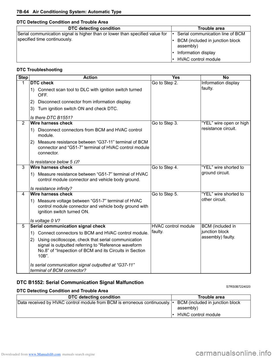
DTC Detecting Condition and Trouble Area
DTC Troubleshooting
DTC B1552: Serial Communication Signal MalfunctionS7RS0B7224020
DTC Detecting Condition and Trouble AreaDTC detecting condition Trouble area
Serial communication signal is higher than or lower than specified value for
specified time continuously. • Serial communication line of BCM
• BCM (included in junction block
assembly)
• Information display
• HVAC control module
Step Action YesNo
1 DTC check
1) Connect scan tool to DLC with ignition switch turned
OFF.
2) Disconnect connector from information display.
3) Turn ignition switch ON and check DTC.
Is there DTC B1551? Go to Step 2.
Information display
faulty.
2 Wire harness check
1) Disconnect connectors from BCM and HVAC control
module.
2) Measure resistance between “G37-11” terminal of BCM connector and “G51-7” terminal of HVAC control module
connector.
Is resistance below 5
Ω? Go to Step 3. “YEL” wire open or high
resistance circuit.
3 Wire harness check
1) Measure resistance between “G51-7” terminal of HVAC
control module connector and vehicle body ground.
Is resistance infinity? Go to Step 4. “YEL” wire shorted to
ground circuit.
4 Wire harness check
1) Measure voltage between “G51-7” terminal of HVAC
control module connector and vehicle body ground with
ignition switch turned ON.
Is voltage 0 V? Go to Step 5. “YEL” wire shorted to
other circuit.
5 Serial communication signal check
1) Connect connectors to BCM and HVAC control module.
2) Using oscilloscope, check that serial communication
signal is outputted referring to “Reference waveform
No.8” of “Inspection of BCM and its Circuits in Section
10B”.
Is serial communication signal outputted at “G37-11”
terminal of BCM connector? HVAC control module
faulty.
BCM (included in
junction block
assembly) faulty.
DTC detecting condition
Trouble area
Data received by HVAC control module from BCM is erroneous continuously. • BCM (included in junction block assembly)
• HVAC control module
Page 1013 of 1496
Downloaded from www.Manualslib.com manuals search engine Air Conditioning System: Automatic Type 7B-65
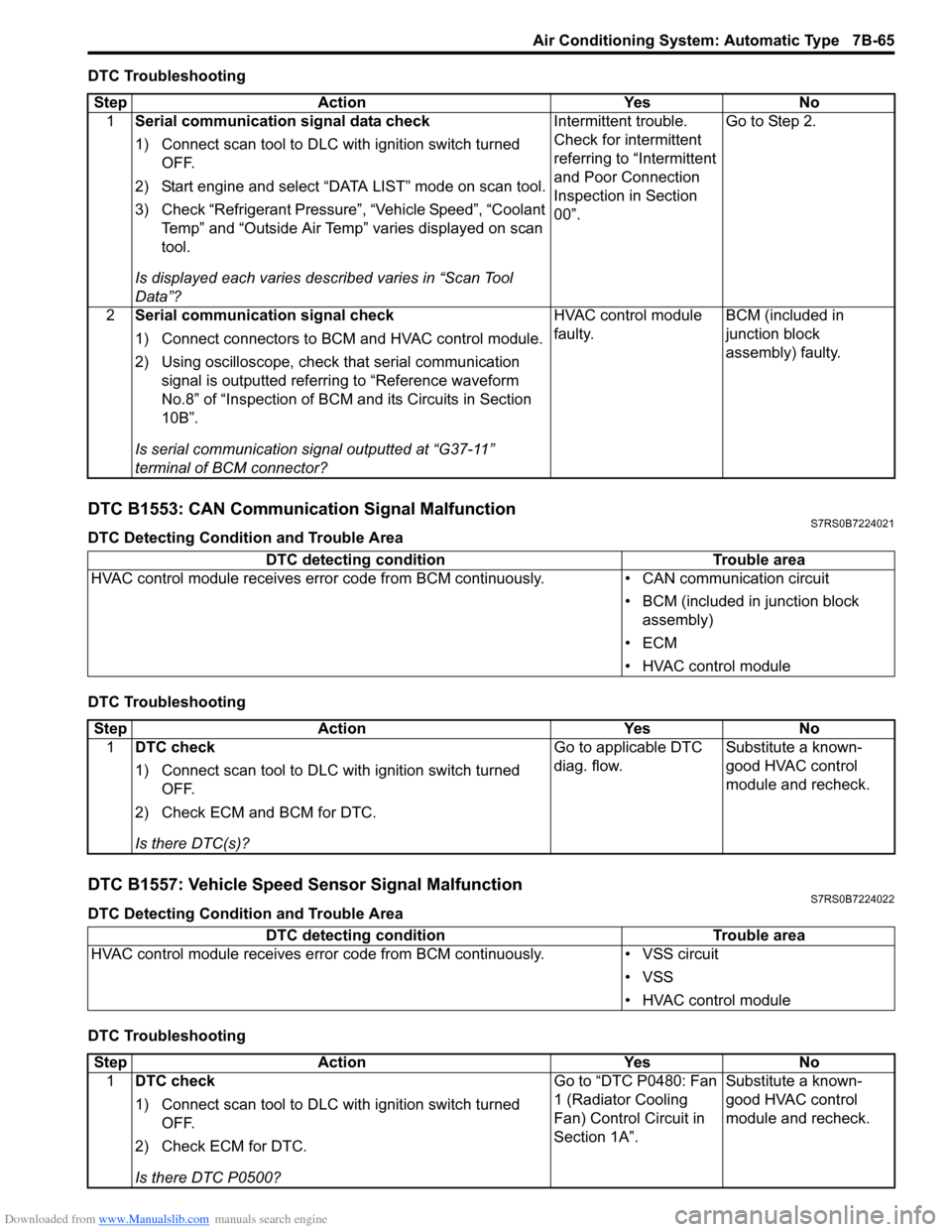
DTC Troubleshooting
DTC B1553: CAN Communication Signal MalfunctionS7RS0B7224021
DTC Detecting Condition and Trouble Area
DTC Troubleshooting
DTC B1557: Vehicle Speed Sensor Signal MalfunctionS7RS0B7224022
DTC Detecting Condition and Trouble Area
DTC TroubleshootingStep Action Yes No
1 Serial communication signal data check
1) Connect scan tool to DLC with ignition switch turned
OFF.
2) Start engine and select “DATA LIST” mode on scan tool.
3) Check “Refrigerant Pressure”, “Vehicle Speed”, “Coolant Temp” and “Outside Air Temp” varies displayed on scan
tool.
Is displayed each va ries described varies in “Scan Tool
Data”? Intermittent trouble.
Check for intermittent
referring to “Intermittent
and Poor Connection
Inspection in Section
00”.
Go to Step 2.
2 Serial communication signal check
1) Connect connectors to BCM and HVAC control module.
2) Using oscilloscope, check that serial communication
signal is outputted referring to “Reference waveform
No.8” of “Inspection of BCM and its Circuits in Section
10B”.
Is serial communication signal outputted at “G37-11”
terminal of BCM connector? HVAC control module
faulty.
BCM (included in
junction block
assembly) faulty.
DTC detecting condition
Trouble area
HVAC control module receives error code fr om BCM continuously.• CAN communication circuit
• BCM (included in junction block assembly)
•ECM
• HVAC control module
Step Action YesNo
1 DTC check
1) Connect scan tool to DLC with ignition switch turned
OFF.
2) Check ECM and BCM for DTC.
Is there DTC(s)? Go to applicable DTC
diag. flow.
Substitute a known-
good HVAC control
module and recheck.
DTC detecting condition
Trouble area
HVAC control module receives error code from BCM continuously. • VSS circuit
• VSS
• HVAC control module
Step Action YesNo
1 DTC check
1) Connect scan tool to DLC with ignition switch turned
OFF.
2) Check ECM for DTC.
Is there DTC P0500? Go to “DTC P0480: Fan
1 (Radiator Cooling
Fan) Control Circuit in
Section 1A”.
Substitute a known-
good HVAC control
module and recheck.
Page 1317 of 1496
Downloaded from www.Manualslib.com manuals search engine Instrumentation / Driver Info. / Horn: 9C-22
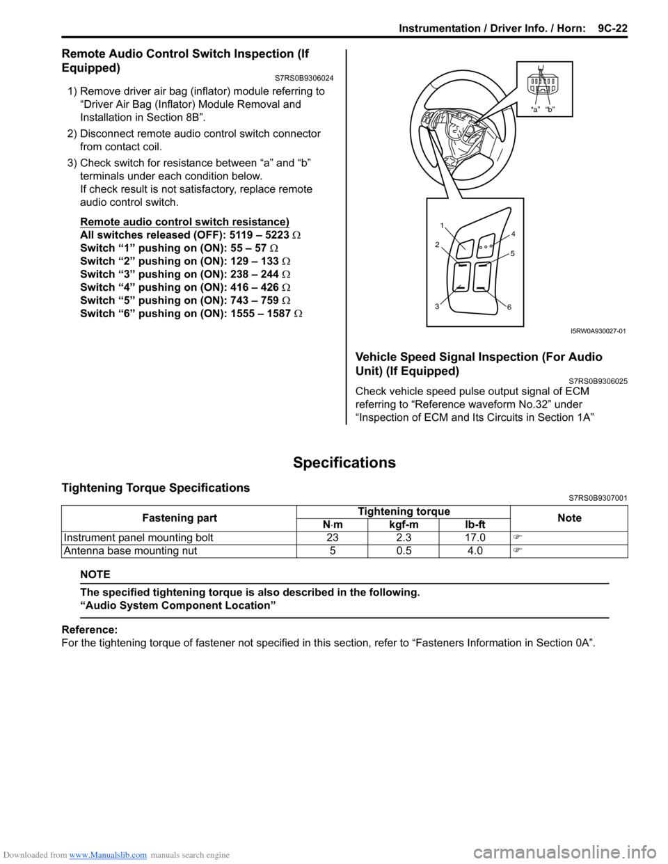
Remote Audio Control Switch Inspection (If
Equipped)
S7RS0B9306024
1) Remove driver air bag (inflator) module referring to
“Driver Air Bag (Inflator) Module Removal and
Installation in Section 8B”.
2) Disconnect remote audio control switch connector
from contact coil.
3) Check switch for resistance between “a” and “b” terminals under each condition below.
If check result is not satisfactory, replace remote
audio control switch.
Remote audio control switch resistance)
All switches released (OFF): 5119 – 5223 Ω
Switch “1” pushing on (ON): 55 – 57 Ω
Switch “2” pushing on (ON): 129 – 133 Ω
Switch “3” pushing on (ON): 238 – 244 Ω
Switch “4” pushing on (ON): 416 – 426 Ω
Switch “5” pushing on (ON): 743 – 759 Ω
Switch “6” pushing on (ON): 1555 – 1587 Ω
Vehicle Speed Signal Inspection (For Audio
Unit) (If Equipped)
S7RS0B9306025
Check vehicle speed pulse output signal of ECM
referring to “Reference waveform No.32” under
“Inspection of ECM and Its Circuits in Section 1A”
Specifications
Tightening Torque SpecificationsS7RS0B9307001
NOTE
The specified tightening torque is also described in the following.
“Audio System Component Location”
Reference:
For the tightening torque of fastener not specified in this section, refer to “Fasteners Information in Section 0A”.
“b”“a”
1
2
3 4
5
6
I5RW0A930027-01
Fastening part Tightening torque
Note
N ⋅mkgf-mlb-ft
Instrument panel mounting bolt 23 2.3 17.0 �)
Antenna base mounting nut 5 0.5 4.0 �)
Page 1434 of 1496
Downloaded from www.Manualslib.com manuals search engine 10B-31 Body Electrical Control System:
Inspection of BCM and its CircuitsS7RS0BA204018
BCM and its circuits can be checked at BCM wiring couplers by measuring voltage and resistance.
CAUTION!
BCM cannot be checked by itself. It is strictly prohibited to connect voltmeter or ohmmeter to BCM
with couplers disconnected from it.
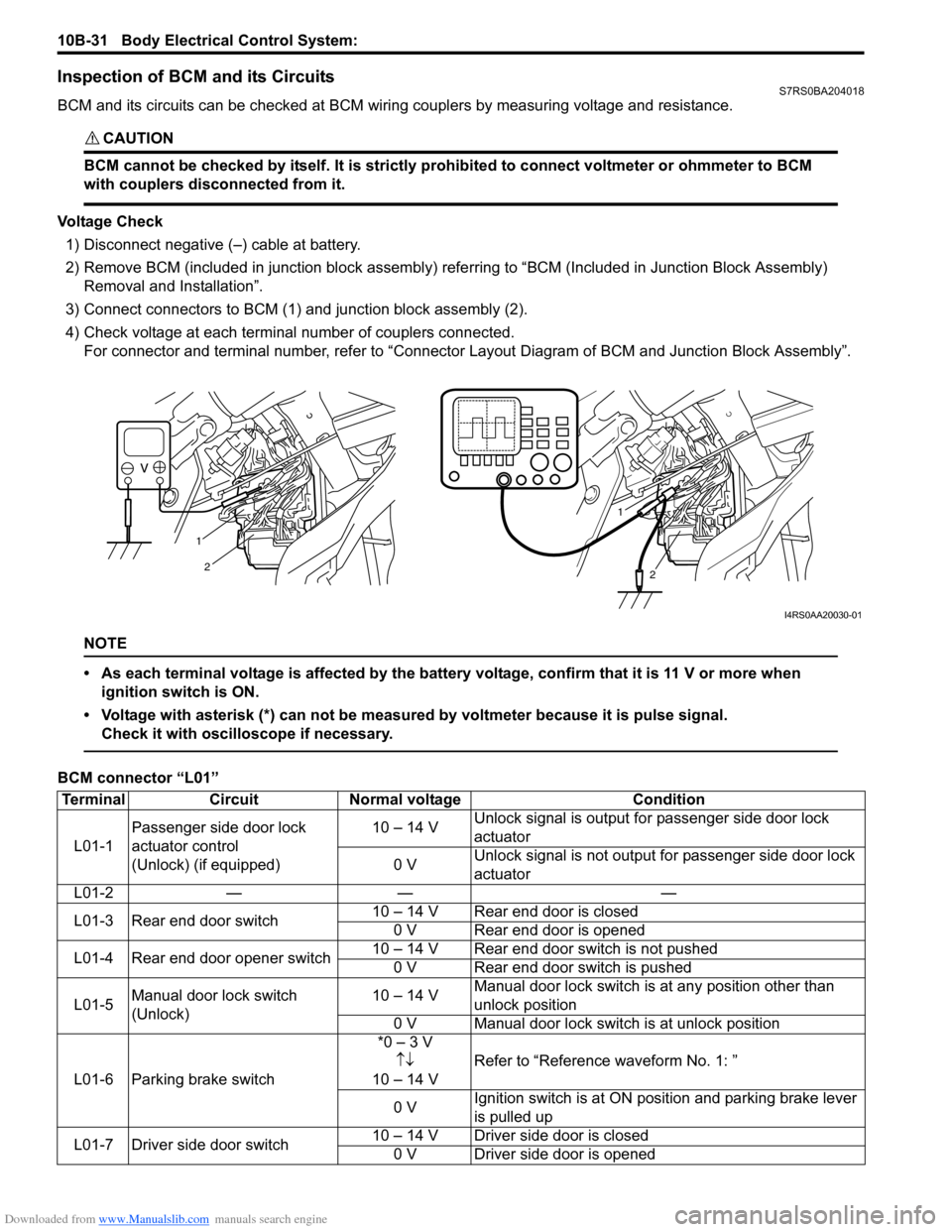
Voltage Check1) Disconnect negative (–) cable at battery.
2) Remove BCM (included in junction block assembly) refe rring to “BCM (Included in Junction Block Assembly)
Removal and Installation”.
3) Connect connectors to BCM (1) and junction block assembly (2).
4) Check voltage at each terminal number of couplers connected. For connector and terminal number, refer to “Connector Layout Diagram of BCM and Junction Block Assembly”.
NOTE
• As each terminal voltage is affected by the battery voltage, confirm that it is 11 V or more when
ignition switch is ON.
• Voltage with asterisk (*) can not be measured by voltmeter because it is pulse signal. Check it with oscilloscope if necessary.
BCM connector “L01”
1
2
1
2
I4RS0AA20030-01
Terminal CircuitNormal voltage Condition
L01-1 Passenger side door lock
actuator control
(Unlock) (if equipped) 10 – 14 V
Unlock signal is output fo
r passenger side door lock
actuator
0 V Unlock signal is not output for passenger side door lock
actuator
L01-2 — — —
L01-3 Rear end door switch 10 – 14 V Rear end door is closed
0 V Rear end door is opened
L01-4 Rear end door opener switch 10 – 14 V Rear end door switch is not pushed
0 V Rear end door switch is pushed
L01-5 Manual door lock switch
(Unlock) 10 – 14 V
Manual door lock switch is at any position other than
unlock position
0 V Manual door lock switch is at unlock position
L01-6 Parking brake switch *0 – 3 V
↑↓
10 – 14 V Refer to “Reference waveform No. 1: ”
0 V Ignition switch is at ON po
sition and parking brake lever
is pulled up
L01-7 Driver side door switch 10 – 14 V Driver side door is closed
0 V Driver side door is opened
Page 1435 of 1496
Downloaded from www.Manualslib.com manuals search engine Body Electrical Control System: 10B-32
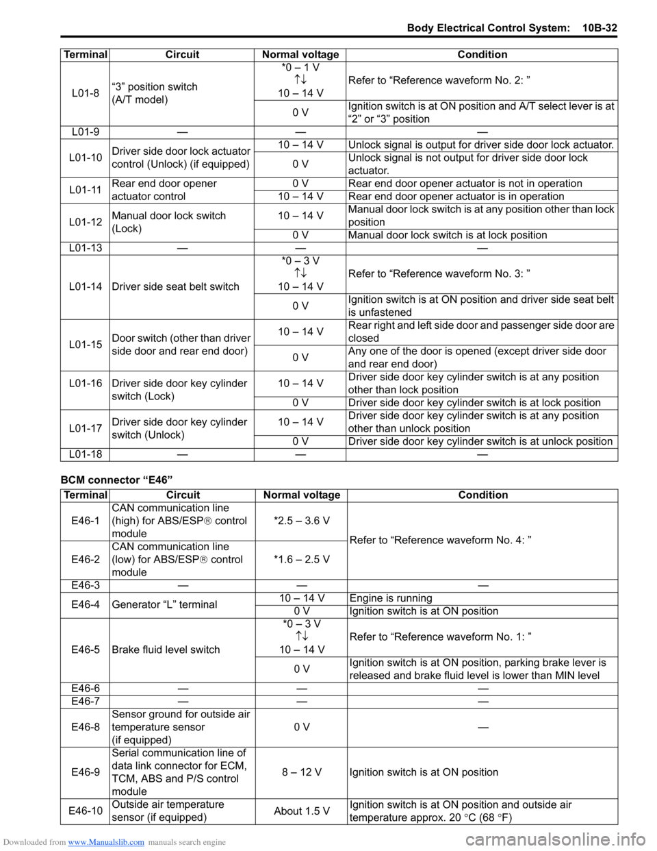
BCM connector “E46”L01-8
“3” position switch
(A/T model) *0 – 1 V
↑↓
10 – 14 V Refer to “Reference waveform No. 2: ”
0 V Ignition switch is at ON positi
on and A/T select lever is at
“2” or “3” position
L01-9 — — —
L01-10 Driver side door lock actuator
control (Unlock) (if equipped) 10 – 14 V Unlock signal is output for driver side door lock actuator.
0 V Unlock signal is not output for driver side door lock
actuator.
L01-11 Rear end door opener
actuator control 0 V Rear end door opener actuator is not in operation
10 – 14 V Rear end door opener actuator is in operation
L01-12 Manual door lock switch
(Lock) 10 – 14 V
Manual door lock switch is at any position other than lock
position
0 V Manual door lock swit ch is at lock position
L01-13 — — —
L01-14 Driver side seat belt switch *0 – 3 V
↑↓
10 – 14 V Refer to “Reference waveform No. 3: ”
0 V Ignition switch is at ON position and driver side seat belt
is unfastened
L01-15 Door switch (other than driver
side door and rear end door) 10 – 14 V
Rear right and left side door and passenger side door are
closed
0 V Any one of the door is opened (except driver side door
and rear end door)
L01-16 Driver side door key cylinder switch (Lock) 10 – 14 V
Driver side door key cylinder switch is at any position
other than lock position
0 V Driver side door key cylinder switch is at lock position
L01-17 Driver side door key cylinder
switch (Unlock) 10 – 14 V
Driver side door key cylinder switch is at any position
other than unlock position
0 V Driver side door key cylinder switch is at unlock position
L01-18 — — —
Terminal Circuit Normal voltage Condition
Terminal
CircuitNormal voltage Condition
E46-1 CAN communication line
(high) for ABS/ESP
® control
module *2.5 – 3.6 V
Refer to “Reference waveform No. 4: ”
E46-2 CAN communication line
(low) for ABS/ESP
® control
module *1.6 – 2.5 V
E46-3 — — —
E46-4 Generator “L” terminal 10 – 14 V Engine is running
0 V Ignition switch is at ON position
E46-5 Brake fluid level switch *0 – 3 V
↑↓
10 – 14 V Refer to “Reference waveform No. 1: ”
0 V Ignition switch is at ON position, parking brake lever is
released and brake fluid level is lower than MIN level
E46-6 — — —
E46-7 — — —
E46-8 Sensor ground for outside air
temperature sensor
(if equipped) 0 V
—
E46-9 Serial communication line of
data link connector for ECM,
TCM, ABS and
P/S control
module 8 – 12 V Ignition switch is at ON position
E46-10 Outside air temperature
sensor (if equipped) About 1.5 VIgnition switch is at ON position and outside air
temperature approx. 20
°C (68 °F)