Page 1074 of 1496
Downloaded from www.Manualslib.com manuals search engine 8B-36 Air Bag System:
2 1) With ignition switch OFF, disconnect “L32” connector located near the glove box.
2) Check proper connection to floor harness connector at terminal “L32-1” and “L32-2”.
3) If OK, then connect special tools (B) and (D) to “L32” connector.
Special tool
(B): 09932–75010
(D): 09932–77320
4) Check SDM DTC.
NOTE
At this time, DTC B1041 ma y be output, but it is
not related to this check.
With ignition switch ON , is DTC B1033 indicated? Go to Step 3. “GRN/RED” circuit or
“GRN” circuit shorted to
ground in instrument
panel harness.
Step Action Yes No
(B) (D)
"L32"BASE OF COLUMN
DRIVERPASSENGER
I4RS0A820015-01
Page 1079 of 1496
Downloaded from www.Manualslib.com manuals search engine Air Bag System: 8B-41
2 1) With ignition switch OFF, disconnect “L32” connector located near the glove box.
2) Check proper connection to floor harness connector at terminal “L32-1” and “L32-2”.
3) If OK, then connect special tools (B) and (D) to “L32” connector.
Special tool
(B): 09932–75010
(D): 09932–77320
4) Check SDM DTC.
NOTE
At this time, DTC B1041 ma y be output, but it is
not related to this check.
With ignition switch ON , is DTC B1034 indicated? Go to Step 3. “GRN/RED” circuit or
“GRN” circuit shorted to
power supply circuit in
instrument panel
harness.
Step Action Yes No
(B) (D)
"L32"BASE OF COLUMN
DRIVERPASSENGER
I4RS0A820015-01
Page 1084 of 1496
Downloaded from www.Manualslib.com manuals search engine 8B-46 Air Bag System:
2 1) With ignition switch OFF, disconnect “L32” connector located near the glove box.
2) Check proper connection to floor harness connector at terminal “L32-3” and “L32-4”.
3) If OK, then connect special tools (B) and (C) to “L32” connector disconnected in Step 1).
Special tool
(B): 09932-75010
(C): 09932–77320
4) Check SDM DTC.
NOTE
At this time, DTC B1031 ma y be output, but it is
not related to this check.
With ignition switch ON , is DTC B1041 indicated? Go to Step 3. High resistance or open
wire “BLU/RED” or
“YEL/RED” circuit in
instrument panel
harness.
Step Action Yes No
(B) (C)
"L32"STEERING WHEEL
DRIVERPASSENGER
I4RS0A820022-01
Page 1087 of 1496
Downloaded from www.Manualslib.com manuals search engine Air Bag System: 8B-49
2 1) With ignition switch OFF, disconnect “L32” connector located near the glove box.
2) Check proper connection to floor harness connector at terminal “L32-3” and “L32-4”.
3) If OK, then connect special tools (B) and (C) to “L32” connector disconnected in Step 1).
Special tool
(B): 09932-75010
(C): 09932–77320
4) Check SDM DTC.
NOTE
At this time, DTC B1031 ma y be output, but it is
not related to this check.
With ignition switch ON , is DTC B1042 indicated? Go to Step 3. “BLU/RED” circuit
shorted to “YEL/RED”
circuit, “BLU/RED”
circuit or “YEL/RED”
circuit shorted to other
circuit in instrument
panel harness.
Step Action Yes No
(B)
(C)
"L32"STEERING WHEEL
DRIVERPASSENGER
I4RS0A820022-01
Page 1090 of 1496
Downloaded from www.Manualslib.com manuals search engine 8B-52 Air Bag System:
2 1) With ignition switch OFF, disconnect “L32” connector located near the glove box.
2) Check proper connection to floor harness connector at terminal “L32-3” and “L32-4”.
3) If OK, then connect special tools (B) and (C) to “L32” connector disconnected in Step 1).
Special tool
(B): 09932-75010
(C): 09932–77320
4) Check SDM DTC.
NOTE
At this time, DTC B1031 ma y be output, but it is
not related to this check.
With ignition switch ON , is DTC B1043 indicated? Go to Step 3. “BLU/RED” or “YEL/
RED” circuit shorted to
ground in instrument
panel harness.
Step Action Yes No
(B) (C)
"L32"STEERING WHEEL
DRIVERPASSENGER
I4RS0A820022-01
Page 1093 of 1496
Downloaded from www.Manualslib.com manuals search engine Air Bag System: 8B-55
2 1) With ignition switch OFF, disconnect “L32” connector located near the glove box.
2) Check proper connection to floor harness connector at terminal “L32-3” and “L32-4”.
3) If OK, then connect special tools (B) and (C) to “L32” connector disconnected in Step 1).
Special tool
(B): 09932-75010
(C): 09932–77320
4) Check SDM DTC.
NOTE
At this time, DTC B1031 ma y be output, but it is
not related to this check.
With ignition switch ON , is DTC B1044 indicated? Go to Step 3. “BLU/RED” or “YEL/
RED” circuit shorted to
power supply circuit in
instrument panel
harness.
Step Action Yes No
(B) (C)
"L32"STEERING WHEEL
DRIVERPASSENGER
I4RS0A820022-01
Page 1136 of 1496

Downloaded from www.Manualslib.com manuals search engine 8B-98 Air Bag System:
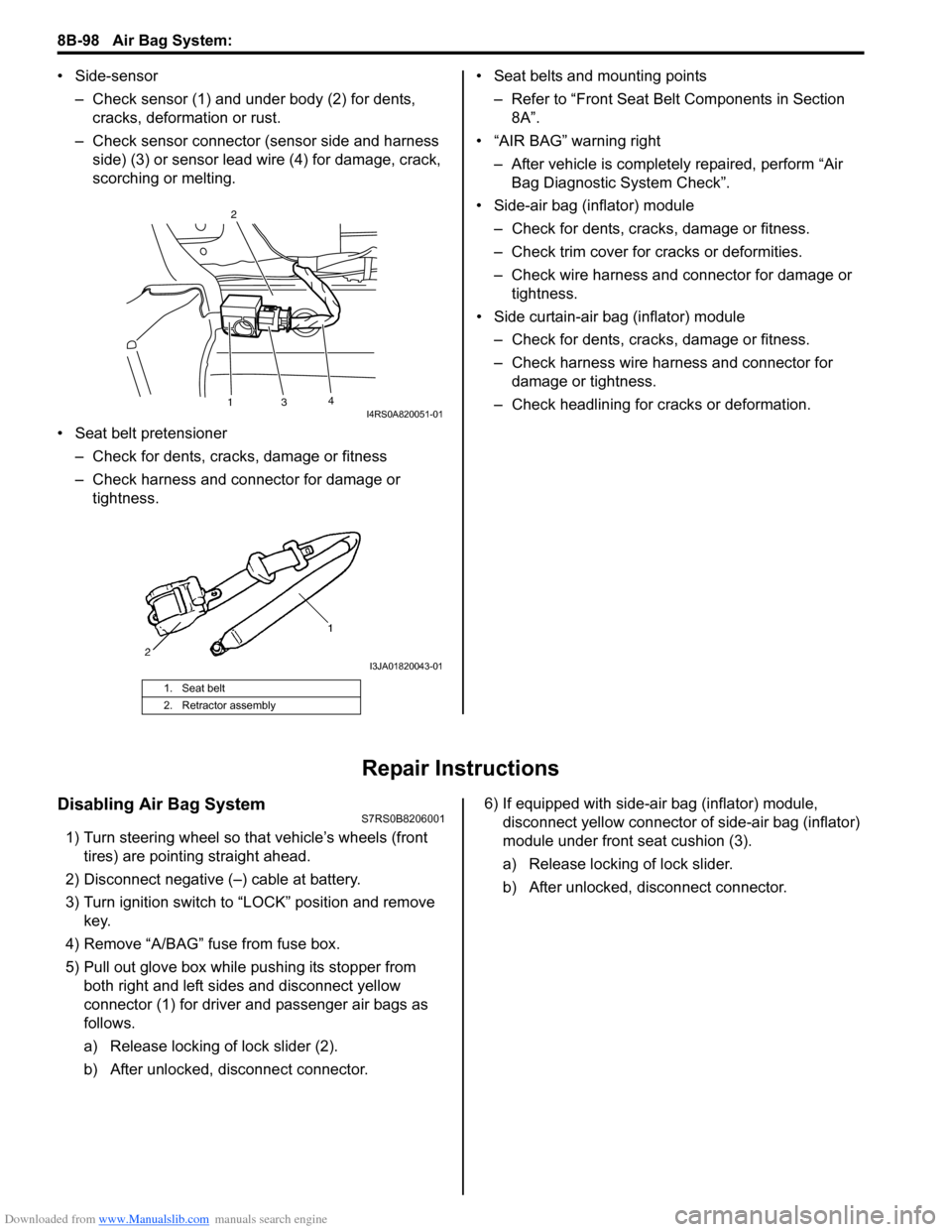
• Side-sensor– Check sensor (1) and under body (2) for dents, cracks, deformation or rust.
– Check sensor connector (sensor side and harness side) (3) or sensor lead wire (4) for damage, crack,
scorching or melting.
• Seat belt pretensioner – Check for dents, cracks , damage or fitness
– Check harness and connector for damage or tightness. • Seat belts and mounting points
– Refer to “Front Seat Belt Components in Section 8A”.
• “AIR BAG” warning right
– After vehicle is completely repaired, perform “Air Bag Diagnostic System Check”.
• Side-air bag (inflator) module – Check for dents, cra cks, damage or fitness.
– Check trim cover for cracks or deformities.
– Check wire harness and connector for damage or tightness.
• Side curtain-air bag (inflator) module – Check for dents, cra cks, damage or fitness.
– Check harness wire harness and connector for damage or tightness.
– Check headlining for cracks or deformation.
Repair Instructions
Disabling Air Bag SystemS7RS0B8206001
1) Turn steering wheel so that vehicle’s wheels (front tires) are pointing straight ahead.
2) Disconnect negative (–) cable at battery.
3) Turn ignition switch to “LOCK” position and remove key.
4) Remove “A/BAG” fu se from fuse box.
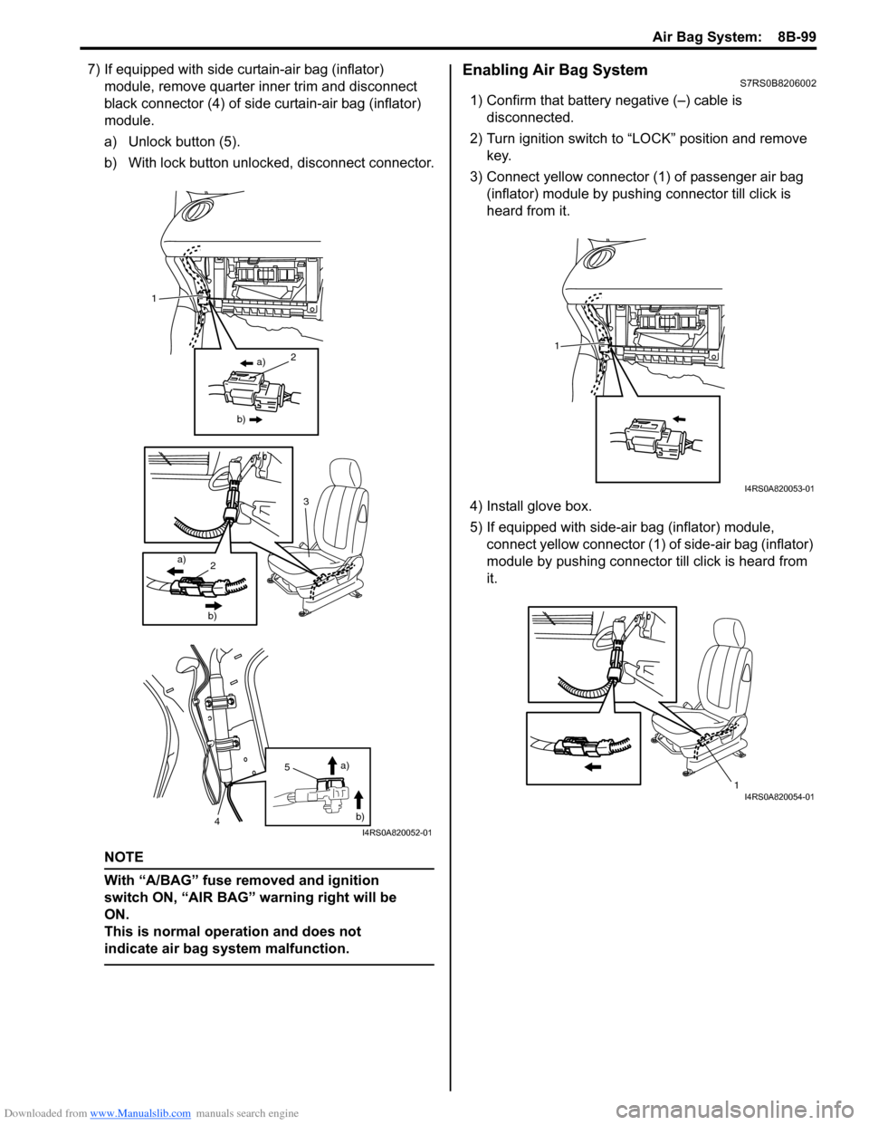
5) Pull out glove box while pushing its stopper from
both right and left sides and disconnect yellow
connector (1) for driver and passenger air bags as
follows.
a) Release locking of lock slider (2).
b) After unlocked, disconnect connector. 6) If equipped with side-air bag (inflator) module,
disconnect yellow connector of side-air bag (inflator)
module under front seat cushion (3).
a) Release locking of lock slider.
b) After unlocked, disconnect connector.
1. Seat belt
2. Retractor assembly
13 4
2I4RS0A820051-01
I3JA01820043-01
Page 1137 of 1496

Downloaded from www.Manualslib.com manuals search engine Air Bag System: 8B-99
7) If equipped with side curtain-air bag (inflator) module, remove quarter inner trim and disconnect
black connector (4) of side curtain-air bag (inflator)
module.
a) Unlock button (5).
b) With lock button unlocked, disconnect connector.
NOTE
With “A/BAG” fuse removed and ignition
switch ON, “AIR BAG” warning right will be
ON.
This is normal operation and does not
indicate air bag system malfunction.
Enabling Air Bag SystemS7RS0B8206002
1) Confirm that battery negative (–) cable is disconnected.
2) Turn ignition switch to “LOCK” position and remove key.
3) Connect yellow connector (1) of passenger air bag (inflator) module by push ing connector till click is
heard from it.
4) Install glove box.
5) If equipped with side-air bag (inflator) module, connect yellow connector (1) of side-air bag (inflator)
module by pushing connector till click is heard from
it.
a)
b)2
3
2a)
b)
1
5
4 a)
b)
I4RS0A820052-01
1
I4RS0A820053-01
1I4RS0A820054-01