Page 1067 of 1496
Downloaded from www.Manualslib.com manuals search engine Air Bag System: 8B-29
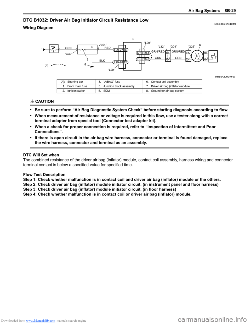
DTC B1032: Driver Air Bag Initiator Circuit Resistance LowS7RS0B8204019
Wiring Diagram
CAUTION!
• Be sure to perform “Air Bag Diagnostic System Check” before starting diagnosis according to flow.
• When measurement of resistance or voltage is required in this flow, use a tester along with a correct terminal adapter from special tool (Connector test adapter kit).
• When a check for proper connection is required, refer to “Inspection of Intermittent and Poor Connections”.
• If there is open circuit in the air bag wire harnes s, connector or terminal is found damaged, replace
the wire harness, connector and terminal as an assembly.
DTC Will Set when
The combined resistance of the driver air bag (inflator) module, contact coil assembly, harness wiring and connector
terminal contact is below a spec ified value for specified time.
Flow Test Description
Step 1: Check whether malfunction is in contact coil and driver air bag (inflator) module or the others.
Step 2: Check driver air bag (inflator) module initiator circuit. (in instrument panel and floor harness)
Step 3: Check driver air bag (inflator) module initiator circuit. (in floor harness)
Step 4: Check whether malfunction is in contact coil or driver air bag (inflator) module.
1 2
3
GRN
RED
8
BLK
L29-27
L29-28 IG
E1
4
“L29”
“L04”
“G32”
“L29”
L29-4
D+
L29-3
D-GRN
GRN/RED
GRN
GRN/RED 6
57
“G26”
“L32” “G04”
[A]
I7RS0A820010-07
[A]: Shorting bar 3. “A/BAG” fuse 6. Contact coil assembly
1. From main fuse 5. Junction block assembly 7. Driver air bag (inflator) module
2. Ignition switch 5. SDM 8. Ground for air bag system
Page 1072 of 1496
Downloaded from www.Manualslib.com manuals search engine 8B-34 Air Bag System:
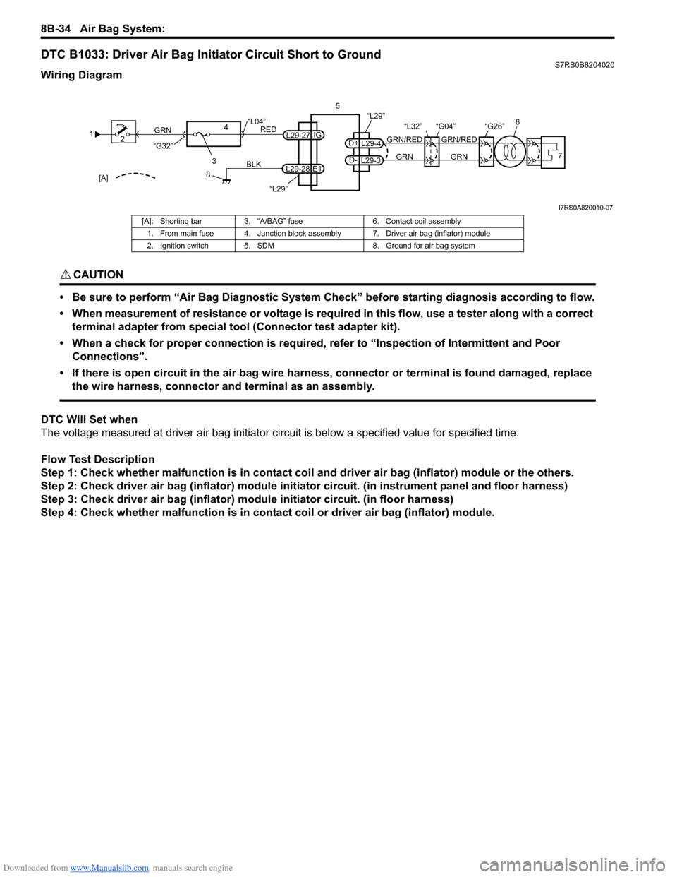
DTC B1033: Driver Air Bag Initiator Circuit Short to GroundS7RS0B8204020
Wiring Diagram
CAUTION!
• Be sure to perform “Air Bag Diagnostic System Check” before starting diagnosis according to flow.
• When measurement of resistance or voltage is required in this flow, use a tester along with a correct terminal adapter from special tool (Connector test adapter kit).
• When a check for proper connection is required, refer to “Inspection of Intermittent and Poor Connections”.
• If there is open circuit in the air bag wire harnes s, connector or terminal is found damaged, replace
the wire harness, connector and terminal as an assembly.
DTC Will Set when
The voltage measured at driver air bag initiator ci rcuit is below a specified value for specified time.
Flow Test Description
Step 1: Check whether malfunction is in contact coil and driver air bag (inflator) module or the others.
Step 2: Check driver air bag (inflator) module initiator circuit. (in instrument panel and floor harness)
Step 3: Check driver air bag (inflator) module initiator circuit. (in floor harness)
Step 4: Check whether malfunction is in contact coil or driver air bag (inflator) module.
1 2
3
GRN
RED
8
BLK
L29-27
L29-28 IG
E1
4
“L29”
“L04”
“G32”
“L29”
L29-4
D+
L29-3
D-GRN
GRN/RED
GRN
GRN/RED 6
57
“G26”
“L32” “G04”
[A]
I7RS0A820010-07
[A]: Shorting bar 3. “A/BAG” fuse 6. Contact coil assembly
1. From main fuse 4. Junction block assembly 7. Driver air bag (inflator) module
2. Ignition switch 5. SDM 8. Ground for air bag system
Page 1077 of 1496
Downloaded from www.Manualslib.com manuals search engine Air Bag System: 8B-39
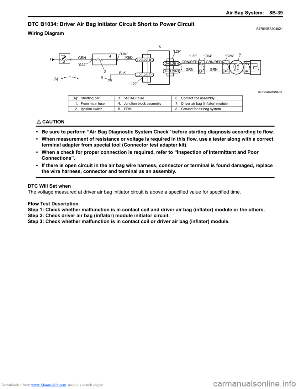
DTC B1034: Driver Air Bag Initiator Circuit Short to Power CircuitS7RS0B8204021
Wiring Diagram
CAUTION!
• Be sure to perform “Air Bag Diagnostic System Check” before starting diagnosis according to flow.
• When measurement of resistance or voltage is required in this flow, use a tester along with a correct terminal adapter from special tool (Connector test adapter kit).
• When a check for proper connection is required, refer to “Inspection of Intermittent and Poor Connections”.
• If there is open circuit in the air bag wire harnes s, connector or terminal is found damaged, replace
the wire harness, connector and terminal as an assembly.
DTC Will Set when
The voltage measured at driver air bag initiator ci rcuit is above a specified value for specified time.
Flow Test Description
Step 1: Check whether malfunction is in contact coil and driver air bag (inflator) module or the others.
Step 2: Check driver air bag (inflator) module initiator circuit.
Step 3: Check whether malfunction is in contact coil or driver air bag (inflator) module.
1 2
3
GRN
RED
8
BLK
L29-27
L29-28 IG
E1
4
“L29”
“L04”
“G32”
“L29”
L29-4
D+
L29-3
D-GRN
GRN/RED
GRN
GRN/RED 6
57
“G26”
“L32” “G04”
[A]
I7RS0A820010-07
[A]: Shorting bar 3. “A/BAG” fuse 6. Contact coil assembly
1. From main fuse 4. Junction block assembly 7. Driver air bag (inflator) module
2. Ignition switch 5. SDM 8. Ground for air bag system
Page 1172 of 1496
Downloaded from www.Manualslib.com manuals search engine 9A-1 Wiring Systems:
Body, Cab and Accessories
Wiring Systems
Precautions
Cautions in Body Electrical System ServicingS7RS0B9100001
When servicing the electric systems, observe the cautions described in “Precautions for Electrical Circuit Service in
Section 00” to protect electrical parts and to prevent a fire.
General Description
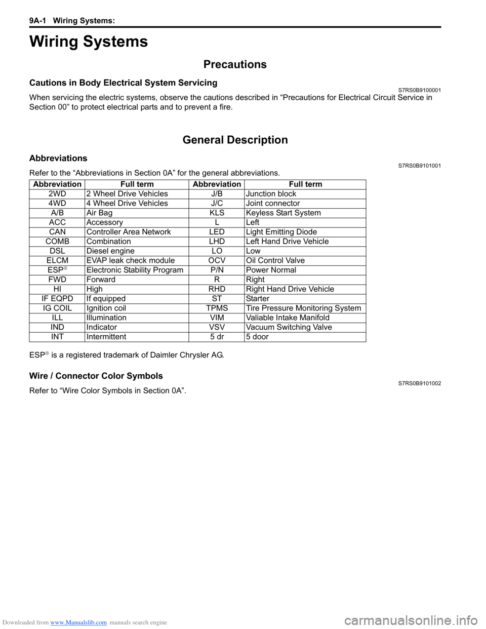
AbbreviationsS7RS0B9101001
Refer to the “Abbreviations in Sect ion 0A” for the general abbreviations.
ESP
® is a registered trademark of Daimler Chrysler AG.
Wire / Connector Color SymbolsS7RS0B9101002
Refer to “Wire Color Sy mbols in Section 0A”.
Abbreviation Full term Abbreviation Full term
2WD 2 Wheel Drive Vehicles J/B Junction block
4WD 4 Wheel Drive Vehicles J/C Joint connectorA/B Air Bag KLS Keyless Start System
ACC Accessory L Left
CAN Controller Area Network LED Light Emitting Diode
COMB Combination LHD Left Hand Drive Vehicle DSL Diesel engine LO Low
ELCM EVAP leak check module OCV Oil Control Valve ESP
®Electronic Stability Program P/N Power Normal
FWD Forward R Right HI High RHD Right Hand Drive Vehicle
IF EQPD If equipped ST Starter IG COIL Ignition coil TPMS Tire Pressure Monitoring System ILL Illumination VIM Valiable Intake Manifold
IND Indicator VSV Vacuum Switching Valve INT Intermittent 5 dr 5 door
Page 1173 of 1496
Downloaded from www.Manualslib.com manuals search engine Wiring Systems: 9A-2
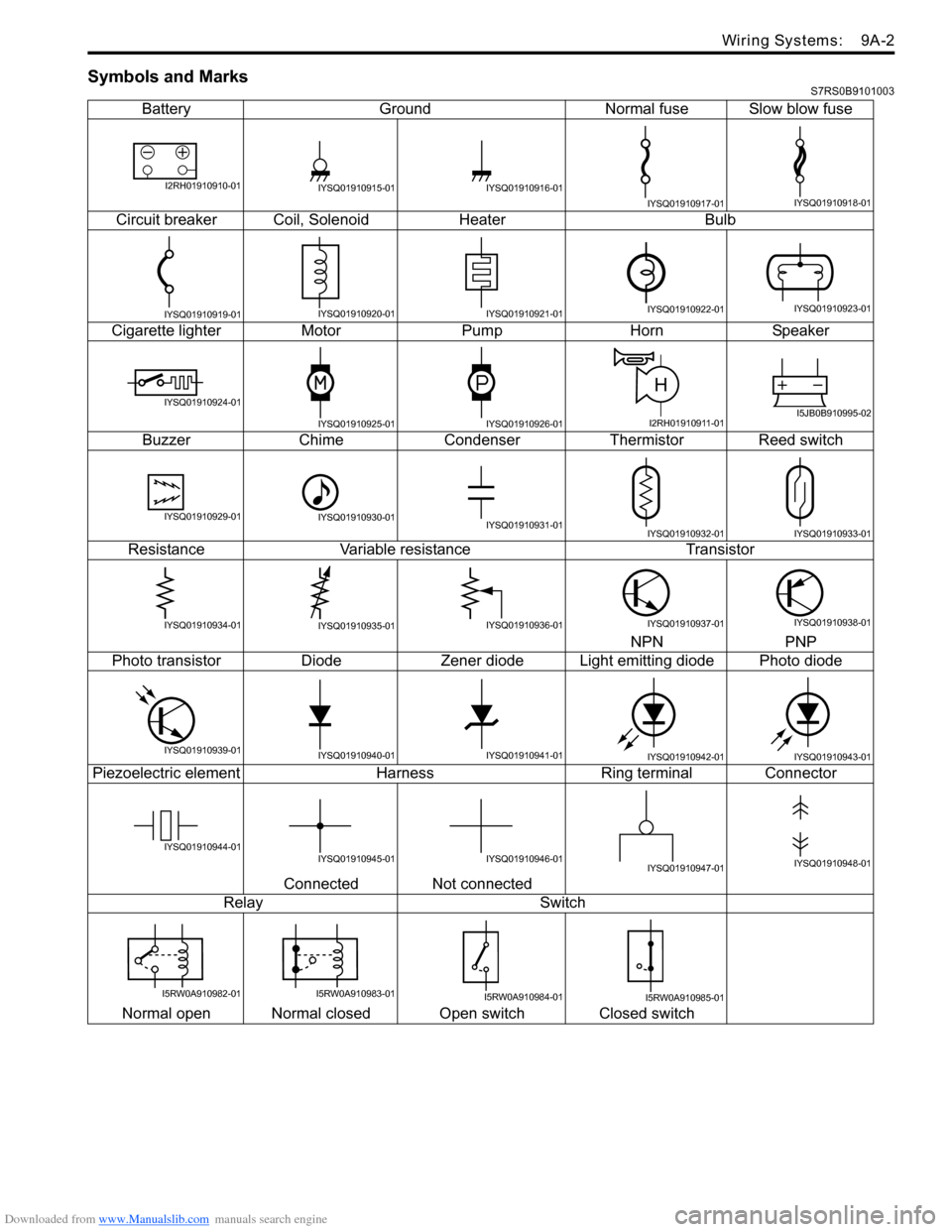
Symbols and MarksS7RS0B9101003
BatteryGroundNormal fuse Slow blow fuse
Circuit breaker Coil, SolenoidHeater Bulb
Cigarette lighter MotorPump HornSpeaker
Buzzer ChimeCondenser Thermistor Reed switch
Resistance Variable resistance Transistor
NPN PNP
Photo transistor DiodeZener diode L ight emitting diode Photo diode
Piezoelectric element Harness Ring terminal Connector
Connected Not connected
Relay Switch
Normal open Normal closed Open switch Closed switch
I2RH01910910-01IYSQ01910915-01IYSQ01910916-01
IYSQ01910917-01IYSQ01910918-01
IYSQ01910919-01IYSQ01910920-01IYSQ01910921-01IYSQ01910922-01IYSQ01910923-01
IYSQ01910924-01
IYSQ01910925-01IYSQ01910926-01
H
I2RH01910911-01I5JB0B910995-02
IYSQ01910929-01IYSQ01910930-01IYSQ01910931-01IYSQ01910932-01IYSQ01910933-01
IYSQ01910934-01IYSQ01910935-01IYSQ01910936-01IYSQ01910937-01IYSQ01910938-01
IYSQ01910939-01IYSQ01910940-01IYSQ01910941-01IYSQ01910942-01IYSQ01910943-01
IYSQ01910944-01IYSQ01910945-01IYSQ01910946-01IYSQ01910947-01IYSQ01910948-01
I5RW0A910982-01I5RW0A910983-01I5RW0A910984-01I5RW0A910985-01
Page 1177 of 1496
Downloaded from www.Manualslib.com manuals search engine Wiring Systems: 9A-6
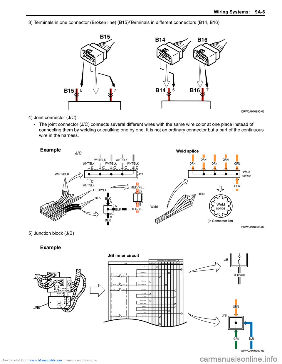
3) Terminals in one connector (Broken line) (B15)/Terminals in different connectors (B14, B16)
4) Joint connector (J/C)• The joint connector (J/C) connects several different wires with the same wire color at one place instead of
connecting them by welding or caulking one by one. It is not an ordinary connector but a part of the continuous
wire in the harness.
5) Junction block (J/B)
B15 B15
B14 B1657B14 B1657
I5RW0A910995-03
BLKBLK
A
A
A B
B
RED/YEL
WeldORN
WHT/BLK
J/C
Weld splice
BLKBLK
RED/YEL
RED/YEL
WHT/BLK
WHT/BLK
WHT/BLKWHT/BLKWHT/BLKWHT/BLKC
CCCCCWeld
splice
(in Connector list)
J/C
ORNORNORNORNORN
ORN
Weld
splice
Example
I5RW0A910989-02
IMMOBI IG IG1IG Coil, etc E39 E41E40
BCM G34
G33
G32 K01 L04 L05 L06
IG Coil
IG1
15A
MTR10A
A/B15A
2
65
13
J/B Connector No. / Terminal No.
BCM ;IG1
MTR Power, etc
A/B CONTK-LINE K-LINE
A/B SIGNAL
A/B SIGNAL
A/B SIG
A/B SIG
IG Sig 10AEPS ATMTA
4
6
1
3
24
8
11
9
12
9
11
23
25
30
29
Example
J/B
J/B
ORN
GRNBLU
J/B
J/B inner circuit
BLK/WHT
I5RW0A910990-03
Page 1182 of 1496

Downloaded from www.Manualslib.com manuals search engine 9A-11 Wiring Systems:
C: Engine harnessNo./Color Connective position No./Color Connective positionC01/GRY IAC valve C22/- Generator #2
C02/GRY IG Coil #1 C23/BLK Starting motor #1
C03/GRY IG Coil #2 C24/- Starting motor #2
C04/GRY Fuel injector #1 C25/GR Y VSS (Vehicle speed sensor)
C05/GRY Fuel injector #2 C26/GRY Knock sensor
C06/GRY Fuel injector #3 C27/BLU (A/
T) Input shaft speed sensor
C07/GRY Fuel injector #4 C28/GRY
(A/T) Trans axle range sensor
C08/BLK or GRY CMP sensor C29/GRY
(A/T) Shift solenoid
C09/BLK ECT sensor C30/BLK
(M/T) Back-up light switch
C10/GRY EGR stepper motor C31/- Main fuse box C11/BLK Throttle position sensor C32/GRY
(IF EQPD) Current sensor
C12/BLK MAP sensor C33/- Main fuse box
C13/BLK MAF sensor C34/N (A/T) TCM
C14/BLK EVAP canister purge valve C35/N (A/T) TCM
C15/GRY Heated oxygen sensor #1 C36/N Main harness (To E24)
C16/GRN Heated oxygen sensor #2 C37/GRY ECM C17/BLK A/C compressor C38/- Weld splice C18/N Oil pressure switch C39/- Weld splice
C19/BLU VVT solenoid C40/- Weld splice
C20/GRY CKP sensor C41/- Weld splice
C21/GRY or BLK Generator #1
Page 1184 of 1496

Downloaded from www.Manualslib.com manuals search engine 9A-13 Wiring Systems:
C: Engine harness
D: Oil pressure switch wireNo./Color Connective position No./Color Connective position
C02/GRY IG Coil #1 C24/- Starting motor #2
C03/GRY IG Coil #2 C23/BLK Starting motor #1
C04/GRY Fuel injector #1 C25/GRY
(A/T) VSS (Vehicle speed sensor)
C05/GRY Fuel injector #2 C26/GRY Knock shaft speed sensor
C06/GRY Fuel injector #3 C27/BLU (A/
T) Input shaft speed sensor
C07/GRY Fuel injector #4 C28/GRY
(A/T) Trans axle range sensor
C08/BLK CMP sensor C29/GRY
(A/T) Shift solenoid
C09/BLK ECT sensor C30/BLK
(M/T) Back-up light switch
C10/GRY EGR stepper motor C31/- Main fuse box C12/BLK MAP sensor C32/GRY Current sensor
C13/BLK MAF sensor C33/- Main fuse box
C14/BLK EVAP canister purge valve C34/N (A/T) TCM
C15/BLK Heated oxygen sensor #1 C35/N (A/T) TCM
C16/GRN Heated oxygen sensor #2 C36/N Main harness (To E24) C17/BLK A/C compressor C37/GRY ECM C18/N Oil pressure switch wire (To D02) C38/- Weld splice
C19/BLU VVT solenoid C39/- Weld splice
C20/GRY CKP sensor C40/- Weld splice C21/BLK Generator #1 C42/BLK Electric throttle body C22/- Generator #2
No./Color Connective position No./ColorConnective position
D01/N Oil pressure switch D02/GRY Engine harness (To C18)