2007 SUZUKI SWIFT Bearing
[x] Cancel search: BearingPage 413 of 1496
Downloaded from www.Manualslib.com manuals search engine Charging System: 1J-3
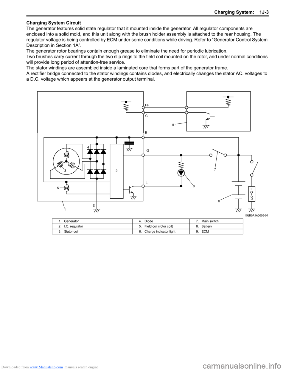
Charging System Circuit
The generator features solid state regulator that it mounted inside the generator. All regulator components are
enclosed into a solid mold, and this unit along with the brus h holder assembly is attached to the rear housing. The
regulator voltage is being controlled by ECM under some cond itions while driving. Refer to “Generator Control System
Description in Section 1A”.
The generator rotor bearings contain enough grease to eliminate the need for periodic lubrication.
Two brushes carry current through the two slip rings to the field coil mounted on the rotor, and under normal conditions
will provide long period of attention-free service.
The stator windings are assembled inside a laminate d core that forms part of the generator frame.
A rectifier bridge connected to the stator windings contains diodes, and electrically changes the stator AC. voltages to
a D.C. voltage which appears at the generator output terminal.
I5JB0A1A0005-01
1. Generator 4. Diode7. Main switch
2. I.C. regulator 5. Field coil (rotor coil)8. Battery
3. Stator coil 6. Charge indicator light9. ECM
Page 414 of 1496

Downloaded from www.Manualslib.com manuals search engine 1J-4 Charging System:
Diagnostic Information and Procedures
Battery InspectionS7RS0B1A04001
Common Causes of Failure
A battery is not designed to last indefinitely; however, with proper care, it will provide many years of service. If the
battery performs satisfactorily during te st but fails to operate properly for no apparent reason, the following are some
factors that may point to the cause of trouble:
• Accessories left on overnight or for an extended period without the generator operating.
• Slow average driving speeds for short periods.
• Electrical load exceeding generator output partic ularly with addition of aftermarket equipment.
• Defects in charging system such as high resistance, s lipping drive belt, loose generator output terminal, faulty
generator or voltage regulator, Refer to “Generator Symptom Diagnosis”.
• Battery abuse, including failure to keep battery cable terminals clean and tight or loose battery hold down.
• Mechanical problems in electrical sys tem such as shorted or pinched wires.
Visual Inspection
Check for obvious damage, such as cracked or broken case or cover, that could permit loss of electrolyte. If obvious
damage is noted, replace battery. Determine cause of damage and correct as needed.
Generator Symptom DiagnosisS7RS0B1A04002
CAUTION!
• Do not mistake polarities of “IG” terminal and “L” terminal.
• Do not create short circuit between “IG” and “L” terminals. Always connect these terminals through a lamp.
• Do not connect any load between “L” and “E” terminals.
• When connecting charger or booster battery to vehicle battery, refer to “Jump Starting in Case of Emergency”.
Trouble in charging system will show up as one or more of the following conditions:
1) Faulty indicator lamp operation.
2) An undercharged battery as evidenced by slow cranking or indicator dark.
3) An overcharged battery as evidenced by ex cessive spewing of electrolyte from vents.
Condition Possible cause Correction / Reference Item
Noisy generator Loose drive belt Adjust or replace drive belt.
Loose drive belt pulley Tighten by specified torque.
Loose mounting bolts Tighten by specified torque.
Worn or dirty bearings Replace.
Defective diode or stator Replace.
Charge light does not
light with ignition ON and
engine off Fuse blown
Replace fuse and check for shorted circuit.
Indicator lamp (LED) faulty Replace combination meter.
Wiring connection loose Tighten loose connection.
IC regulator or field coil faulty Replace.
Poor contact between brush and slip
ring Repair or replace.
Charge light does not go
out with engine running
(battery requires frequent
recharging) Drive belt loose or worn
Adjust or replace drive belt.
IC regulator or generator faulty Replace.
Wiring faulty Repair wiring.
Page 420 of 1496
Downloaded from www.Manualslib.com manuals search engine 1J-10 Charging System:
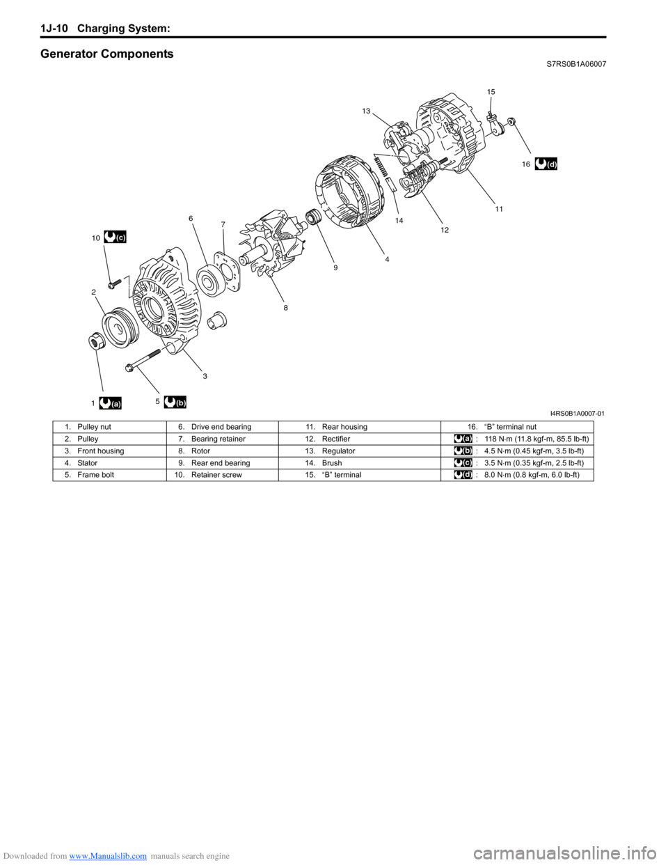
Generator ComponentsS7RS0B1A06007
1211
13
14
(a)(b)
(c)
(d)
1 2
3 4
56
7
89
10 15
16
I4RS0B1A0007-01
1. Pulley nut 6. Drive end bearing 11. Rear housing 16. “B” terminal nut
2. Pulley 7. Bearing retainer 12. Rectifier : 118 N⋅m (11.8 kgf-m, 85.5 lb-ft)
3. Front housing 8. Rotor 13. Regulator : 4.5 N⋅m (0.45 kgf-m, 3.5 lb-ft)
4. Stator 9. Rear end bearing 14. Brush : 3.5 N⋅m (0.35 kgf-m, 2.5 lb-ft)
5. Frame bolt 10. Retainer screw 15. “B” terminal : 8.0 N⋅m (0.8 kgf-m, 6.0 lb-ft)
Page 429 of 1496
Downloaded from www.Manualslib.com manuals search engine Table of Contents 2- i
2
Section 2
CONTENTS
Suspension
Precautions ................................................. 2-1
Precautions............................................................. 2-1
Precautions on Suspension .................................. 2-1
Suspension General Dia gnosis.............. 2A-1
Diagnostic Information and Procedures ............ 2A-1
Suspension, Wheels and Tires Symptom Diagnosis .......................................................... 2A-1
Front Suspension ........... ......................... 2B-1
General Description ............................................. 2B-1
Front Suspension Construction ........................... 2B-1
Front Wheel Alignment Cons truction .................. 2B-2
Repair Instructions .............................................. 2B-2 Front Wheel Alignment Inspection and Adjustment ........................................................ 2B-2
Front Strut Assembly Comp onents ..................... 2B-4
Front Strut Assembly Removal and Installation ......................................................... 2B-4
Front Strut Assembly Disassembly and Assembly .......................................................... 2B-6
Front Strut Assembly Chec k ............................... 2B-7
Front Wheel Hub and Steering Knuckle Components...................................................... 2B-8
Front Wheel Hub, Steering Knuckle and Wheel Bearing Removal and Installation .......... 2B-8
Front Wheel Hub, Disc, Nut and Bearing Check .............................................................. 2B-12
Suspension Control Arm / Bushing Removal and Installation ................................................ 2B-12
Suspension Control Arm / Bushing Disassembly and Assembly ............................ 2B-13
Suspension Control Arm / Steering Knuckle Check .............................................................. 2B-14
Suspension Control Arm Bushing Check .......... 2B-14
Suspension Control Arm Joint Check ............... 2B-14
Front Suspension Fram e, Stabilizer Bar and/
or Bushings Components................................ 2B-15
Front Suspension Fram e, Stabilizer Bar and/
or Bushings Removal and Installation ............. 2B-15
Front Suspension Frame Ch eck ....................... 2B-19
Front Stabilizer Bar, Bushing and/or Joint Check .............................................................. 2B-19
Front Suspension Fastener s Check .................. 2B-19
Specifications ..................................................... 2B-20 Tightening Torque Specifications ...................... 2B-20
Special Tools and Equipmen t ...........................2B-21
Special Tool ...................................................... 2B-21
Rear Suspension ............ ......................... 2C-1
General Description .............................................2C-1
Rear Suspension Construction ...........................2C-1
Repair Instructions ........... ...................................2C-2
Rear Wheel Alignment Inspection .......................2C-2
Rear Shock Absorber Removal and Installation .........................................................2C-2
Rear Shock Absorber Ins pection ........................2C-3
Rear Shock Absorber Bush Removal and Installation .........................................................2C-4
Rear Shock Absorber Bush Inspection ...............2C-4
Rear Coil Spring Removal and Installation .........2C-4
Spring Upper Seat / Spring Lower Seat Inspection ..........................................................2C-5
Spring Upper Seat and Lower Seat Removal and Installation ..................................................2C-6
Rear Axle Removal and Inst allation ....................2C-6
Trailing Arm, Rear Axle and Coil Spring Inspection ..........................................................2C-9
Rear Axle Bush Inspection ..................................2C-9
Rear Wheel Hub Components ..........................2C-10
Rear Wheel Hub Removal an d Installation .......2C-10
Rear Wheel Disc, bolt and Bearing Inspection ..2C-11
Spindle Removal and Installation ......................2C-12
Spindle Inspection .............................................2C-13
Rear Suspension Fasteners Inspection ............2C-13
Specifications .................... .................................2C-13
Tightening Torque Specifications ......................2C-13
Special Tools and Equipmen t ...........................2C-13
Special Tool ......................................................2C-13
Wheels and Tires ............ ......................... 2D-1
Precautions...........................................................2D-1
Precaution for Emergency Flat Tire Repair Kit ....2D-1
General Description .............................................2D-1 Tires Description .................................................2D-1
Wheels Description .............................................2D-2
Irregular and/or Premature Wear Description .....2D-3
Wear Indicators Description ................................2D-3
Radial Tire Waddle Description...........................2D-4
Radial Tire Lead / Pull Description ......................2D-5
Page 432 of 1496
Downloaded from www.Manualslib.com manuals search engine 2A-1 Suspension General Diagnosis:
Suspension
Suspension General Diagnosis
Diagnostic Information and Procedures
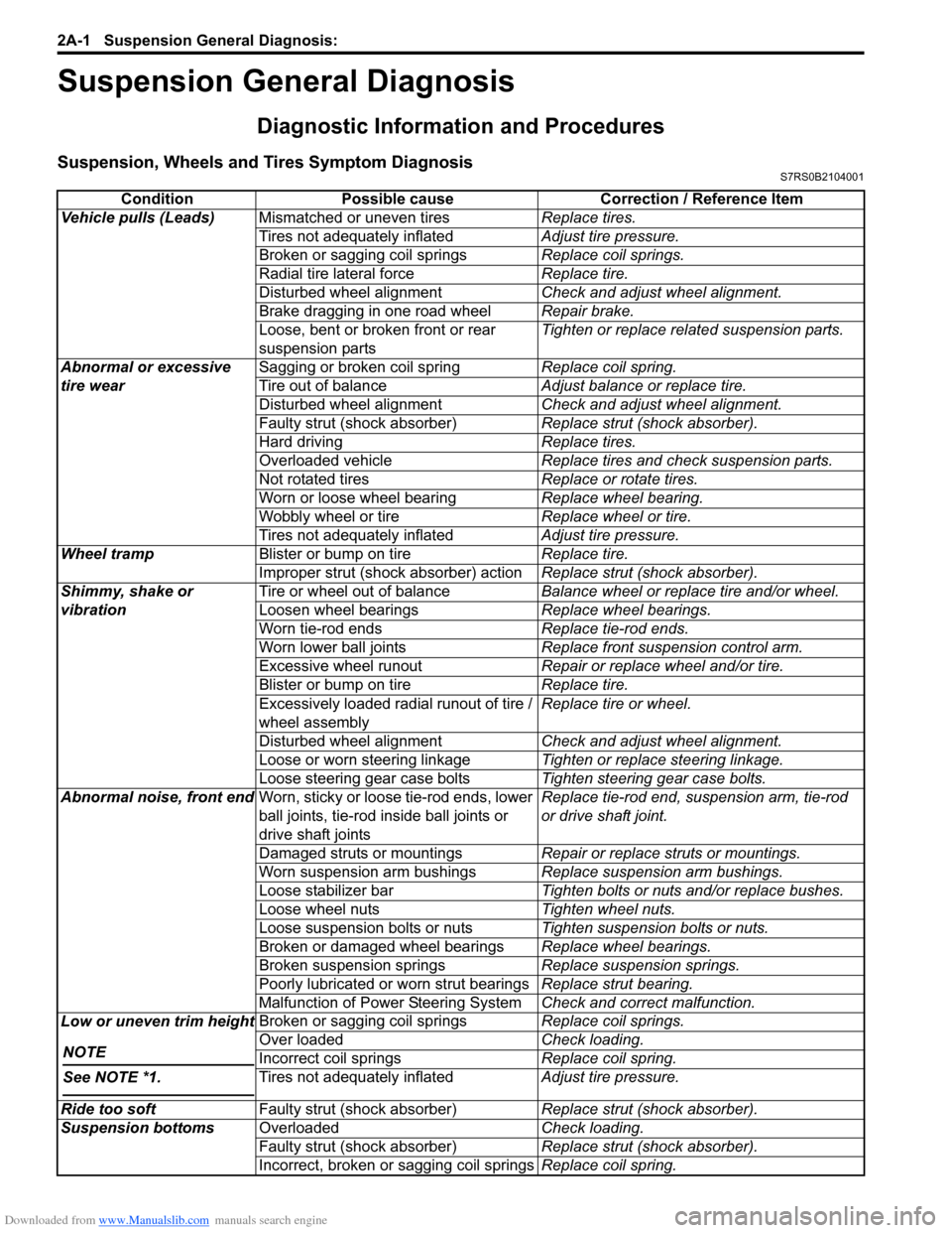
Suspension, Wheels and Tires Symptom DiagnosisS7RS0B2104001
ConditionPossible cause Correction / Reference Item
Vehicle pulls (Leads) Mismatched or uneven tires Replace tires.
Tires not adequately inflated Adjust tire pressure.
Broken or sagging coil springs Replace coil springs.
Radial tire lateral force Replace tire.
Disturbed wheel alignment Check and adjust wheel alignment.
Brake dragging in one road wheel Repair brake.
Loose, bent or broken front or rear
suspension parts Tighten or replace related suspension parts.
Abnormal or excessive
tire wear Sagging or broken coil spring
Replace coil spring.
Tire out of balance Adjust balance or replace tire.
Disturbed wheel alignment Check and adjust wheel alignment.
Faulty strut (shock absorber) Replace strut (shock absorber).
Hard driving Replace tires.
Overloaded vehicle Replace tires and check suspension parts.
Not rotated tires Replace or rotate tires.
Worn or loose wheel bearing Replace wheel bearing.
Wobbly wheel or tire Replace wheel or tire.
Tires not adequately inflated Adjust tire pressure.
Wheel tramp Blister or bump on tire Replace tire.
Improper strut (shock absorber) action Replace strut (shock absorber).
Shimmy, shake or
vibration Tire or wheel out of balance
Balance wheel or replace tire and/or wheel.
Loosen wheel bearings Replace wheel bearings.
Worn tie-rod ends Replace tie-rod ends.
Worn lower ball joints Replace front suspension control arm.
Excessive wheel runout Repair or replace wheel and/or tire.
Blister or bump on tire Replace tire.
Excessively loaded radial runout of tire /
wheel assembly Replace tire or wheel.
Disturbed wheel alignment Check and adjust wheel alignment.
Loose or worn steering linkage Tighten or replace steering linkage.
Loose steering gear case bolts Tighten steering gear case bolts.
Abnormal noise, front end Worn, sticky or loose tie-rod ends, lower
ball joints, tie-rod in side ball joints or
drive shaft joints Replace tie-rod end, su
spension arm, tie-rod
or drive shaft joint.
Damaged struts or mountings Repair or replace struts or mountings.
Worn suspension arm bushings Replace suspension arm bushings.
Loose stabilizer bar Tighten bolts or nuts and/or replace bushes.
Loose wheel nuts Tighten wheel nuts.
Loose suspension bolts or nuts Tighten suspension bolts or nuts.
Broken or damaged wheel bearings Replace wheel bearings.
Broken suspension springs Replace suspension springs.
Poorly lubricated or worn strut bearings Replace strut bearing.
Malfunction of Power Steering System Check and correct malfunction.
Low or uneven trim height
NOTE
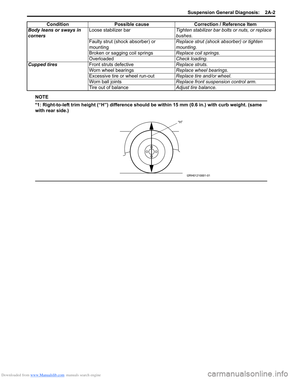
See NOTE *1.
Broken or sagging coil springs Replace coil springs.
Over loaded Check loading.
Incorrect coil springs Replace coil spring.
Tires not adequately inflated Adjust tire pressure.
Ride too soft Faulty strut (shock absorber) Replace strut (shock absorber).
Suspension bottoms Overloaded Check loading.
Faulty strut (shock absorber) Replace strut (shock absorber).
Incorrect, broken or sagging coil springs Replace coil spring.
Page 433 of 1496
Downloaded from www.Manualslib.com manuals search engine Suspension General Diagnosis: 2A-2
NOTE
*1: Right-to-left trim height (“H”) difference should be within 15 mm (0.6 in.) with curb weight. (same
with rear side.)
Body leans or sways in
corners Loose stabilizer bar
Tighten stabilizer bar bolts or nuts, or replace
bushes.
Faulty strut (shock absorber) or
mounting Replace strut (shock absorber) or tighten
mounting.
Broken or sagging coil springs Replace coil springs.
Overloaded Check loading.
Cupped tires Front struts defective Replace struts.
Worn wheel bearings Replace wheel bearings.
Excessive tire or wheel run-out Replace tire and/or wheel.
Worn ball joints Replace front suspension control arm.
Tire out of balance Adjust tire balance.
Condition Possible cause Correction / Reference Item
“H”
I2RH01210001-01
Page 434 of 1496
Downloaded from www.Manualslib.com manuals search engine 2B-1 Front Suspension:
Suspension
Front Suspension
General Description
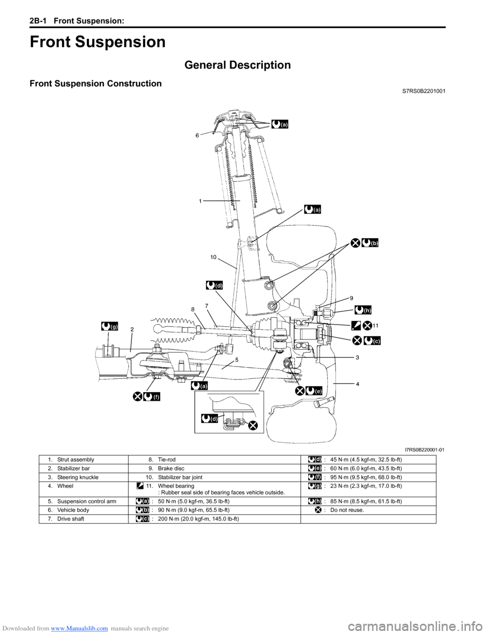
Front Suspension ConstructionS7RS0B2201001
I7RS0B220001-01
1. Strut assembly8. Tie-rod : 45 N⋅m (4.5 kgf-m, 32.5 lb-ft)
2. Stabilizer bar 9. Brake disc : 60 N⋅m (6.0 kgf-m, 43.5 lb-ft)
3. Steering knuckle 10. Stabilizer bar joint : 95 N⋅m (9.5 kgf-m, 68.0 lb-ft)
4. Wheel 11. Wheel bearing
: Rubber seal side of bearing faces vehicle outside. : 23 N
⋅m (2.3 kgf-m, 17.0 lb-ft)
5. Suspension control arm : 50 N⋅m (5.0 kgf-m, 36.5 lb-ft) : 85 N⋅m (8.5 kgf-m, 61.5 lb-ft)
6. Vehicle body : 90 N⋅m (9.0 kgf-m, 65.5 lb-ft) : Do not reuse.
7. Drive shaft : 200 N⋅m (20.0 kgf-m, 145.0 lb-ft)
Page 436 of 1496
Downloaded from www.Manualslib.com manuals search engine 2B-3 Front Suspension:
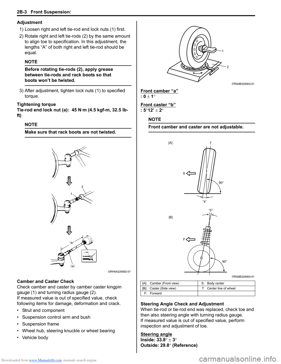
Adjustment1) Loosen right and left tie-rod end lock nuts (1) first.
2) Rotate right and left tie-rods (2) by the same amount to align toe to specification. In this adjustment, the
lengths “A” of both right and left tie-rod should be
equal.
NOTE
Before rotating tie-rods (2), apply grease
between tie-rods and rack boots so that
boots won’t be twisted.
3) After adjustment, tighten lock nuts (1) to specified torque.
Tightening torque
Tie-rod end lock nut (a): 45 N·m (4.5 kgf-m, 32.5 lb-
ft)
NOTE
Make sure that rack boots are not twisted.
Camber and Caster Check
Check camber and caster by camber caster kingpin
gauge (1) and turning radius gauge (2).
If measured value is out of specified value, check
following items for damage, deformation and crack.
• Strut and component
• Suspension control arm and bush
• Suspension frame
• Wheel hub, steering knuckle or wheel bearing
• Vehicle body Front camber “a”
: 0
± 1°
Front caster “b”
: 5 °12’ ± 2°
NOTE
Front camber and caster are not adjustable.
Steering Angle Check and Adjustment
When tie-rod or tie-rod end was replaced, check toe and
then also steering angle with turning radius gauge.
If measured value is out of specified value, perform
inspection and adjustment of toe.
Steering angle
Inside: 33.8 ° ± 3 °
Outside: 29.8 ° (Reference)
I3RH0A220002-01
[A]: Camber (Front view) S: Body center
[B]: Caster (Side view) T: Center line of wheel
F: Forward
2
1
I7RS0B220003-01
[B]
S T
90°
“a”
[A]
F
90°
“b”
I7RS0B220004-01