Page 833 of 1496

Downloaded from www.Manualslib.com manuals search engine Manual Transmission/Transaxle: 5B-19
4) Make reverse idler gear (1) with reverse gear shift lever (2), insert reverse gear shaft (3) into case (4)
through idler gear and then align “A” in shaft with “B”
in case.
5) Fasten reverse gear shift lever bolts after applying thread lock cement.
: Thread lock cement 99000–32110 (Thread Lock
Cement Super 1322)
Tightening torque
Reverse gear shift lever bolt: 23 N·m (2.3 kgf-m,
17.0 lb-ft)
NOTE
• Make sure that washer (5) has been installed in shaft at above the gear.
• Check to confirm that reverse gear shift lever end has clearance “a” to idler gear
groove.
Distance between lever and idler gear shaft
“a”: 0.5 – 1.0 mm (0.02 – 0.04 in.) 6) Clean mating surfaces of both right and left cases,
apply sealant to right case (2) as shown in the figure
by such amount that its section is 1.5 mm (0.059 in.)
in diameter then mate it with left case (1).
“B”: Sealant 99000–31260 (SUZUKI Bond
No.1217G)
7) Install reverse shaft bolt (4) to which thread lock cement has been applied, with aluminum washer
and tighten it to specified torque.
“A”: Thread lock cement 99000–32110 (Thread
Lock Cement Super 1322)
Tightening torque
Reverse shaft bolt (c): 23 N·m (2.3 kgf-m, 17.0
lb-ft)
8) Tighten case bolts (3) from outside tighten another case bolts from clutch housing side to specified
torque.
Tightening torque
Transaxle case bolt (b): 23 N·m (2.3 kgf-m, 17.0
lb-ft)
I4RS0A520036-01
I3RM0A520043-01
Page 836 of 1496

Downloaded from www.Manualslib.com manuals search engine 5B-22 Manual Transmission/Transaxle:
14) With putting a shim (2) on bearing outer race (3), place straightedge (1) over it and compress it by
hand through straightedge, and then measure
clearance “a” between case surface (4) and
straightedge using feeler gauge (5).
Clearance between case surface and
straightedge (Shim protrusion)
“a”: 0.08 – 0.12 mm (0.0032 – 0.0047 in.)
15) By repeating Step 14), select a suitable shim which adjusts clearance “a” to specification and put it on
bearing outer race.
NOTE
Insert 0.10 mm (0.0039 in.) feeler to know
whether or not a shim fulfills specification
quickly.
Available shim thickness
16) Place left case plate (2) inserting its end in groove of shift guide shaft (4) and tighten bolts (1) to which
thread lock cement has been applied.
NOTE
After tightening bolts, make sure that
countershaft (5) can be rotated by hand
feeling certain load.
“A”: Thread lock cement 99000–32110 (Thread
Lock Cement Super 1322)
Tightening torque
Left case plate bolt (a): 23 N·m (2.3 kgf-m, 17.0
lb-ft)
17) Install fifth gear referring to “Fifth Gear Disassembly and Assembly”.
18) Install gear shift and select shaft assembly referring to “Gear Shift and Select Shaft Assembly Removal
and Installation”.
19) Install back up light switch referring to “Back Up Light
Switch Removal and Installation”.
20) Check input shaft for rotation in each gear position.
21) Also confirm continuity of back up light switch in
reverse position using ohmmeter.
0.55 mm (0.021 in.) 0.90 mm (0.035 in.)
0.60 mm (0.023 in.) 0.95 mm (0.037 in.)
0.65 mm (0.025 in.) 1.00 mm (0.039 in.)
0.70 mm (0.027 in.) 1.05 mm (0.041 in.)
0.75 mm (0.029 in.) 1.10 mm (0.043 in.)
0.80 mm (0.031 in.) 1.15 mm (0.059 in.)
0.85 mm (0.033 in.)
I3RM0A520031-01
3. Input shaft
I4RS0A520042-01
Page 838 of 1496
Downloaded from www.Manualslib.com manuals search engine 5B-24 Manual Transmission/Transaxle:
Transaxle Left Case Disassembly and AssemblyS7RS0B5206017
Disassembly1) Replace differential side oil seal from left case referri ng to “Differential Side Oil Seal Replacement”, if necessary.
2) Remove input oil gutter (1) from left case, if necessary.
Assembly 1) If input oil gutter (1) has been removed, install it with bolt to which thread lock cement has been applied.
“A”: Thread lock cement 99000–32110 (Thread Lock Cement Super 1322)
Tightening torque
Oil gutter bolt (a): 10 N·m (1.0 kgf-m, 7.5 lb-ft)
2) If differential side oil seal is remov ed, install it to left case referring to “Differential Side Oil Seal Replacement”.
I4RH01520028-01
I3RM0A520048-01
Page 845 of 1496

Downloaded from www.Manualslib.com manuals search engine Manual Transmission/Transaxle: 5B-31
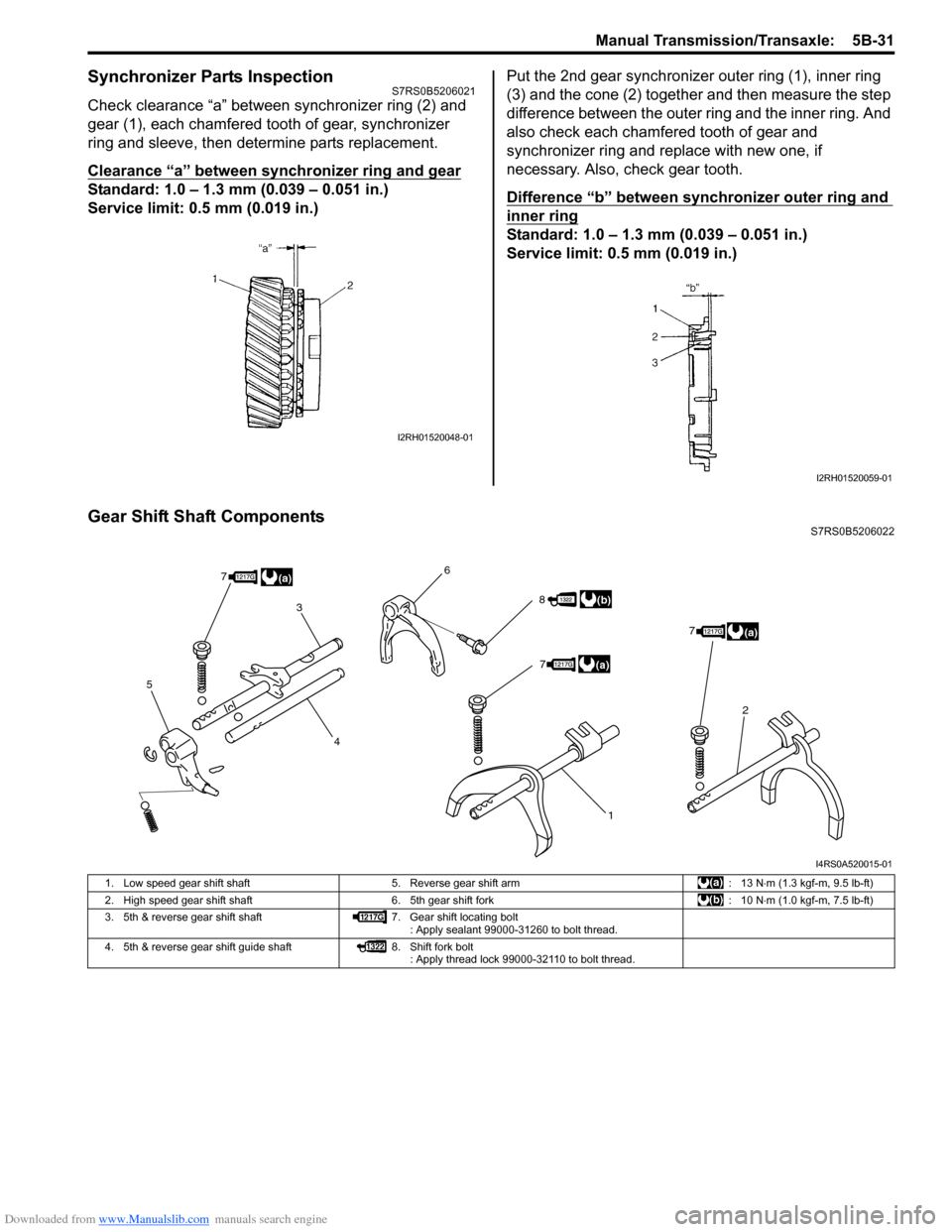
Synchronizer Parts InspectionS7RS0B5206021
Check clearance “a” between synchronizer ring (2) and
gear (1), each chamfered tooth of gear, synchronizer
ring and sleeve, then determine parts replacement.
Clearance “a” between synchronizer ring and gear
Standard: 1.0 – 1.3 mm (0.039 – 0.051 in.)
Service limit: 0.5 mm (0.019 in.)Put the 2nd gear synchronizer outer ring (1), inner ring
(3) and the cone (2) together and then measure the step
difference between the outer ring and the inner ring. And
also check each chamfered tooth of gear and
synchronizer ring and replace with new one, if
necessary. Also, check gear tooth.
Difference “b” between synchronizer outer ring and
inner ring
Standard: 1.0 – 1.3 mm (0.039 – 0.051 in.)
Service limit: 0.5 mm (0.019 in.)
Gear Shift Shaft ComponentsS7RS0B5206022
I2RH01520048-01
I2RH01520059-01
5
3
4 6
1
2
8
7
77
(a)
(b)
(a)
(a)
I4RS0A520015-01
1. Low speed gear shift shaft
5. Reverse gear shift arm : 13 N⋅m (1.3 kgf-m, 9.5 lb-ft)
2. High speed gear shift shaft 6. 5th gear shift fork : 10 N⋅m (1.0 kgf-m, 7.5 lb-ft)
3. 5th & reverse gear shift shaft 7. Gear shift locating bolt
: Apply sealant 99000-31260 to bolt thread.
4. 5th & reverse gear shift guide shaft 8. Shift fork bolt
: Apply thread lock 99000-32110 to bolt thread.
Page 850 of 1496

Downloaded from www.Manualslib.com manuals search engine 5B-36 Manual Transmission/Transaxle:
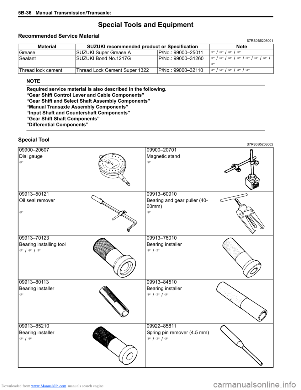
Special Tools and Equipment
Recommended Service MaterialS7RS0B5208001
NOTE
Required service material is also described in the following.
“Gear Shift Control Leve r and Cable Components”
“Gear Shift and Select Shaft Assembly Components”
“Manual Transaxle Assembly Components”
“Input Shaft and Countershaft Components”
“Gear Shift Shaft Components”
“Differential Components”
Special ToolS7RS0B5208002
Material SUZUKI recommended product or Specification Note
Grease SUZUKI Super Grease A P/No.: 99000–25011�) / �) / �) / �)
Sealant SUZUKI Bond No.1217G P/No.: 99000–31260�) / �) / �) / �) / �) / �) / �) /
�)
Thread lock cement Thread Lock Cement Super 1322 P/No.: 99000–32110 �) / �) / �) / �) / �)
09900–20607 09900–20701
Dial gauge Magnetic stand
�)�)
09913–50121 09913–60910
Oil seal remover Bearing and gear puller (40-
60mm)
�)�)
09913–70123 09913–76010
Bearing installing t ool Bearing installer
�) / �) / �)�) / �)
09913–80113 09913–84510
Bearing installer Bearing installer
�)�) / �) / �)
09913–85210 09922–85811
Bearing installer Spring pin remover (4.5 mm)
�) / �)�) / �) / �)
Page 857 of 1496

Downloaded from www.Manualslib.com manuals search engine Clutch: 5C-5
Clutch Pedal Position (CPP) Switch Inspection
and Adjustment
S7RS0B5306005
Inspection
Check for resistance between terminals under each
condition below. If check result is not satisfactory,
replace.
CPP switch resistance
When switch shaft is pushed (1): Continuity
When switch shaft is free (2): No continuityAdjustment
With clutch pedal depressed,
adjust switch (1) position
so that clearance between end of thread and clutch
pedal arm is within specification, and then tighten lock
nut to specified torque.
Clearance between end of thread and clutch pedal
arm
“a”: 3.5 – 4.0 mm (0.14 – 0.16 in.)
Tightening torque
CPP switch lock nut (a): 7.5 N·m (0.75 kgf-m, 5.5 lb-
ft)
Clutch Fluid Pipe and Hose ComponentsS7RS0B5306006
I5JB0A530006-01
(a)
1
“a”
I6RS0C530002-01
6
1
5
2 5
4(a)
3
I6RS0C530003-01
1. Master cylinder
: Apply grease 99000-25100 to push rod end. 5. Clamp
2. Pipe 6. Clutch reservoir hose
3. Operating cylinder : Apply grease 99000-25100 to rod tip. : 23 N
⋅m (2.3 kgf-m, 17.0 lb-ft)
4. Operating cylinder bolt
Page 922 of 1496

Downloaded from www.Manualslib.com manuals search engine 6C-40 Power Assisted Steering System:
Repair Instructions
Steering Gear Case Assembly ComponentsS7RS0B6306001
3(a)
10
(c) 2
3
(a)
2 1
19
(g)
19 18(g) 6
11
8
9
(b) 7
(b)
22 23
24 4
5
14
15
16
(e)
17
(f)
12
(d) 21
(c)
20
4 6
5 7
(b)
9
(b)
8
13
22
23
24
A
A
1322
I7RS0B630013-02
1. Steering gear case 12. Steering gear case mounting No.3 bolt 23. Boot
2. Tie-rod lock washer 13. Gear rack side No.1 bracket 24. split pin
3. Tie-rod 14. Steering rack plunger
: Apply grease 99000-25050 to rack plunger. : 93 N
⋅m (9.3 kgf-m, 67.5 lb-ft)
4. Band 15. Steering rack plunger spring
: Apply grease 99000-25050 to spring end. : 45 N
⋅m (4.5 kgf-m, 32.5 lb-ft)
Refer to “Tie-Rod End Removal and
Installation”.
5. Boot 16. Steering rack damper screw
: Apply thread lock 99000-32110 to all around
thread part of rack damper screw. : 55 N
⋅m (5.5 kgf-m, 40.0 lb-ft)
6. Rack boot clip 17. Steering rack damper lock nut : 40 N⋅m (4.0 kgf-m, 29.0 lb-ft)
7. Tie-rod end lock nut 18. Heat insulator : Refer to “Steering Rack Plunger Removal
and Installation”.
8. Tie-rod end 19. Heat insulator bolt : 64 N⋅m (6.4 kgf-m, 46.5 lb-ft)
Page 923 of 1496

Downloaded from www.Manualslib.com manuals search engine Power Assisted Steering System: 6C-41
Tie-Rod End Boot On-Vehicle InspectionS7RS0B6306002
Check boot for crack and damage.
If any defect is found, replace it with a new one.
Tie-Rod End Removal and InstallationS7RS0B6306003
Removal1) Hoist vehicle, and then remove wheel referring to “Wheel Removal and Installation in Section 2D”.
2) Remove split pin (2) and tie-rod end nut (1) from steering knuckle.
3) Disconnect tie-rod end (1) from knuckle (2) using puller (3). 4) For ease of adjustment after installation, make
marking (1) of tie-rod end lock nut (2) position on tie-
rod end thread. Then, loosen lock nut and remove
tie-rod end (3) from tie-rod (4).
Installation 1) Install tie-rod end lock nut (1) and tie-rod end (2) to tie-rod (3). Align lock nut with mark (4) on tie-rod
thread.
9. Tie-rod end nut 20. Gear rack side No.2 bracket : 9.5 N⋅m (0.95 kgf-m, 7.0 lb-ft)
10. Steering gear case mounting No.1 bolt 21. Steering gear case mounting No.2 bolt : Do not reuse.
11. Steering gear case grommet 22. Clip
I3RM0A630024-01
21
I7RS0A630016-01
2 1
3
I4RS0A630040-01
I4RS0A630041-01
I4RS0A630042-01