2007 SUZUKI SWIFT rear pin
[x] Cancel search: rear pinPage 529 of 1496

Downloaded from www.Manualslib.com manuals search engine Rear Brakes: 4C-5
4) Pass parking brake cable (1) through bracket (3) of caliper.
5) Hang parking brake cable on lever (2) as follows.
NOTE
Make sure that lever (4) contacts pin (5).
6) Install brake pads and caliper referring to “Rear Disc Brake Pad Removal and Installation”.
7) Connect flexible hose (1) with new washers to caliper (2).
WARNING!
Make sure that flexible hose is not twisted
when tightening joint bolt. If it is twisted,
reconnect it using care not to twist it.
Tightening torque
Flexible hose joint bolt (a): 23 N·m (2.3 kgf-m,
17.0 lb-ft) 8) Install brake cable clip (1) securely to bracket (2).
9) After reassembling brake lines, bleed air from them
referring to “Air Bleeding of Brake System in Section
4A”.
10) Check to make sure that system is free from fluid
leakage.
11) Start engine and then depress brake pedal with about 300 N (30 kg, 66 lbs) load 3 times or more so
as to obtain proper disc to pad clearance.
12) Check to make sure that parking brake lever stroke is as specified. Refer to “Parking Brake Inspection
and Adjustment in Section 4D”.
13) Tighten wheel nuts to specified torque.
Tightening torque
Wheel bolt: 85 N·m (8.5 kgf-m, 61.5 lb-ft)
14) Remove vehicle from hoist and perform brake test (foot brake and parking brake).
1
23
45
I6RS0C430010-01
1 (a)2
I6RS0C430011-01
1
2
I6RS0C430012-01
Page 531 of 1496

Downloaded from www.Manualslib.com manuals search engine Rear Brakes: 4C-7
Assembly
CAUTION!
• Wash each part cleanly before installation in the same fluid as the one used in master
cylinder reservoir.
• Never use other fluid or thinner.
• Before installing caliper to brake caliper carrier, install slide pins with grease
applied into carrier hole and check for its
smooth movement in thrust direction.
• Before installing piston seal to cylinder, apply fluid to them.
• Install a piston seal into groove in cylinder securely making sure that it is not twisted.
1) Apply thread lock cement to shaft thread (6) of caliper.
“A”: Thread lock cement 99000–32110 (Thread
Lock Cement Super 1322)
2) Apply grease to inside of new shaft cover (1).
3) Install new shaft cover, leve r (2), washer (3), parking
nut (4) and return spring (5) to caliper.
Tightening torque
Parking nut (a): 27 N·m (2.7 kgf-m, 19.5 lb-ft) 4) Install bleeder plug and cap to caliper.
5) Install new piston seal to caliper.
6) Before inserting piston (2) into cylinder, install boot
(1) onto piston as shown.
7) Fit boot as it is in figure into boot groove in cylinder with fingers.
8) Turn brake caliper piston clockwise to obtain clearance between brake disc and pads.
NOTE
Check that boot is fitted in boot groove
securely all around piston.
Special tool
(A): 09945–16060
5
4, (a)
2
3
1
6, “A”
I6RS0C430016-01
[A]: Cylinder side
[B]: Brake pad side
[A] [B]
I6RS0B431017-01
I6RS0B431033-01
I6RS0B431018-01
Page 532 of 1496

Downloaded from www.Manualslib.com manuals search engine 4C-8 Rear Brakes:
Rear Disc Brake Caliper InspectionS7RS0B4306006
Pin Boot and Cylinder Boot
Check boots (1) for breakage, crack and damage.
If defective, replace.
Disc Brake Piston
Check all around piston for rust, corrosion and any other
damage.
If it is found faulty, replace.
Caliper
Push in adjusting bolt (1) by hand and move lever to
check that adjusting bolt (1) moves smoothly in the
arrow direction.
Also, check adjusting bolt (1) for any damage. If it is
found faulty, replace.
Slide Pin
Check guide pin for smooth movement.
If it is found faulty, correct or replace.
Apply rubber grease to guide pin outer surface. Rubber
grease should be the one whose viscosity is less
affected by such low temperature as –40 °C (–40 ° F).
Rear Flexible Hose Removal and InstallationS7RS0B4306007
Removal
1) Hoist vehicle and remove tire and wheel.
2) Remove caliper (4) assembly referring to “Rear Disc Brake Caliper Disassembly and Assembly”.
3) Loosen brake pipe flare nut (1) using by flare nut wrench.
4) Remove clip (2).
5) Remove brake flexible hose (3) from brake pipe.
Installation
Install reverse order of removal nothing the following.
• Tighten brake pipe flare nut to specified torque.
Tightening torque
Brake pipe flare nut (a): 16 N·m (1.6 kgf-m, 12.0 lb-ft)
1 1
1
I6RS0B431019-01
I6RS0B431020-01
1
I6RS0B431021-01
1
2
3
4
I6RS0C430013-01
Page 534 of 1496

Downloaded from www.Manualslib.com manuals search engine 4C-10 Rear Brakes:
• Using micrometer, measure thickness of brake disc.If limit value is exceeded, replace brake disc.
Rear brake disc thickness
Standard: 9 mm (0.354 in.)
Limit: 8 mm (0.315 in.)
Specifications
Tightening Torque SpecificationsS7RS0B4307001
NOTE
The specified tightening torque is also described in the following.
“Rear Disc Brake Components”
Reference:
For the tightening torque of fastener not specified in this section, refer to “Fasteners Information in Section 0A”.
I6RS0B431032-01
Fastening part Tightening torque
Note
N ⋅mkgf-mlb-ft
Caliper pin bolt 23 2.3 17 �)
Wheel bolt 85 8.5 61.5 �) / �) / �)
Brake caliper carrier bolt 60 6.0 43.5 �)
Flexible hose joint bolt 23 2.3 17.0 �)
Parking nut 27 2.7 19.5 �)
Brake pipe flare nut 16 1.6 12.0 �)
Caliper carrier bolt 60 6.0 43.5 �)
Page 537 of 1496

Downloaded from www.Manualslib.com manuals search engine Parking Brake: 4D-2
Repair Instructions
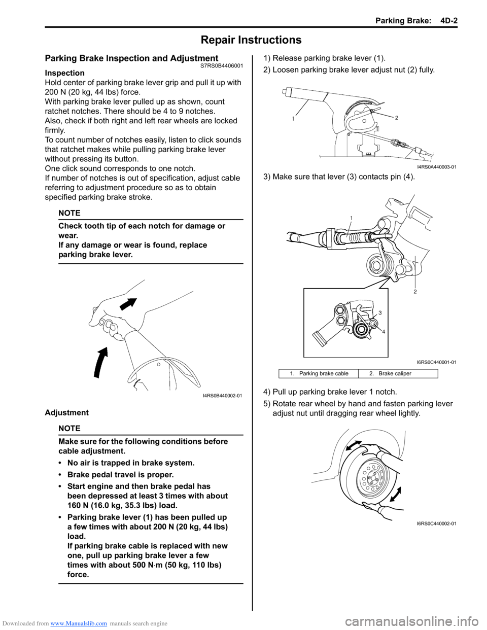
Parking Brake Inspection and AdjustmentS7RS0B4406001
Inspection
Hold center of parking brake lever grip and pull it up with
200 N (20 kg, 44 lbs) force.
With parking brake lever pulled up as shown, count
ratchet notches. There should be 4 to 9 notches.
Also, check if both right and left rear wheels are locked
firmly.
To count number of notches easily, listen to click sounds
that ratchet makes while pulling parking brake lever
without pressing its button.
One click sound corresponds to one notch.
If number of notches is out of specification, adjust cable
referring to adjustment procedure so as to obtain
specified parking brake stroke.
NOTE
Check tooth tip of each notch for damage or
wear.
If any damage or wear is found, replace
parking brake lever.
Adjustment
NOTE
Make sure for the following conditions before
cable adjustment.
• No air is trapped in brake system.
• Brake pedal travel is proper.
• Start engine and then brake pedal has been depressed at least 3 times with about
160 N (16.0 kg, 35.3 lbs) load.
• Parking brake lever (1) has been pulled up a few times with about 200 N (20 kg, 44 lbs)
load.
If parking brake cable is replaced with new
one, pull up parking brake lever a few
times with about 500 N ⋅m (50 kg, 110 lbs)
force.
1) Release parking brake lever (1).
2) Loosen parking brake lever adjust nut (2) fully.
3) Make sure that lever (3) contacts pin (4).
4) Pull up parking brake lever 1 notch.
5) Rotate rear wheel by hand and fasten parking lever adjust nut until dragging rear wheel lightly.
I4RS0B440002-01
1. Parking brake cable 2. Brake caliper
I4RS0A440003-01
I6RS0C440001-01
I6RS0C440002-01
Page 557 of 1496

Downloaded from www.Manualslib.com manuals search engine ABS: 4E-18
DTC C1021, C1022 / C1025, C1026 / C1031, C1032 / C1035, C1036: Right-Front / Left-Front / Right-
Rear / Left-Rear Wheel Speed Sensor Circuit or Sensor Ring
S7RS0B4504012
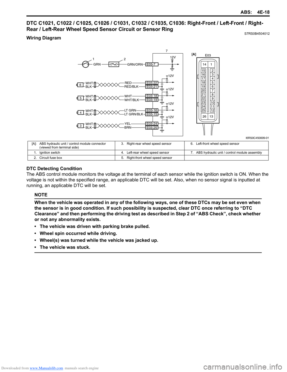
Wiring Diagram
DTC Detecting Condition
The ABS control module monitors the voltage at the terminal of each sensor while the ignition swit ch is ON. When the
voltage is not within the specified range, an applicable DTC will be set. Also, when no sensor signal is inputted at
running, an applicable DTC will be set.
NOTE
When the vehicle was operated in any of the following ways, one of these DTCs may be set even when
the sensor is in good condition. If such possibility is suspected, clear DTC once referring to “DTC
Clearance” and then performing the driving test as described in Step 2 of “ABS Check”, check whether
or not any abnormality exists.
• The vehicle was driven with parking brake pulled.
• Wheel spin occurred while driving.
• Wheel(s) was turned while the vehicle was jacked up.
• The vehicle was stuck.
YELBRN
3E03-24
LT GRN/BLKLT GRN
4
WHTWHT/BLK
5
RED
WHTBLK
WHTBLK
WHTBLK
WHTBLKRED/BLK
6
E03-25
E03-15E03-16
E03-19E03-18
E03-22E03-21
12V
12V
12V
12V
12V
7
GRN/ORNE03-7GRN
1
2
[A]
E03
15
16
17
18
19
20
21
22
23
24
25 2
3
4
5
6
7
8
9
10
11
12
1
13
14
26
I6RS0C450009-01
[A]: ABS hydraulic unit / control module connector
(viewed from terminal side) 3. Right-rear wheel speed sensor 6. Left-front wheel speed sensor
1. Ignition switch 4. Left-rear wheel speed sensor 7. ABS hydraulic unit / control module assembly
2. Circuit fuse box 5. Right-front wheel speed sensor
Page 573 of 1496

Downloaded from www.Manualslib.com manuals search engine ABS: 4E-34
Rear Wheel Speed Sensor InspectionS7RS0B4506009
Refer to “Front Wheel Speed Sensor Inspection” since
rear wheel speed sensor is the same as front wheel
speed sensor.
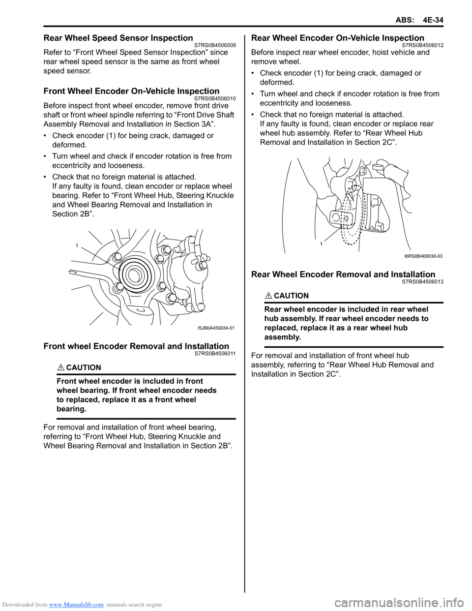
Front Wheel Encoder On-Vehicle InspectionS7RS0B4506010
Before inspect front wheel encoder, remove front drive
shaft or front wheel spindle referring to “Front Drive Shaft
Assembly Removal and Installation in Section 3A”.
• Check encoder (1) for being crack, damaged or deformed.
• Turn wheel and check if encoder rotation is free from eccentricity and looseness.
• Check that no foreign material is attached. If any faulty is found, cl ean encoder or replace wheel
bearing. Refer to “Front Wheel Hub, Steering Knuckle
and Wheel Bearing Removal and Installation in
Section 2B”.
Front wheel Encoder Removal and InstallationS7RS0B4506011
CAUTION!
Front wheel encoder is included in front
wheel bearing. If front wheel encoder needs
to replaced, replace it as a front wheel
bearing.
For removal and installation of front wheel bearing,
referring to “Front Wheel Hub, Steering Knuckle and
Wheel Bearing Removal and Installation in Section 2B”.
Rear Wheel Encoder On-Vehicle InspectionS7RS0B4506012
Before inspect rear wheel encoder, hoist vehicle and
remove wheel.
• Check encoder (1) for being crack, damaged or deformed.
• Turn wheel and check if encoder rotation is free from eccentricity and looseness.
• Check that no foreign material is attached. If any faulty is found, clean encoder or replace rear
wheel hub assembly. Refer to “Rear Wheel Hub
Removal and Installati on in Section 2C”.
Rear Wheel Encoder Removal and InstallationS7RS0B4506013
CAUTION!
Rear wheel encoder is included in rear wheel
hub assembly. If rear wheel encoder needs to
replaced, replace it as a rear wheel hub
assembly.
For removal and installation of front wheel hub
assembly, referring to “Rear Wheel Hub Removal and
Installation in Section 2C”.
1
I5JB0A450034-01
1
I6RS0B460038-03
Page 576 of 1496

Downloaded from www.Manualslib.com manuals search engine 4F-2 Electronic Stability Program:
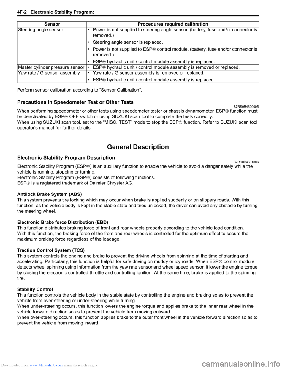
Perform sensor calibration according to “Sensor Calibration”.
Precautions in Speedometer Test or Other TestsS7RS0B4600005
When performing speedometer or other tests using speedometer tester or chassis dynamometer, ESP® function must
be deactivated by ESP ® OFF switch or using SUZUKI scan to ol to complete the tests correctly.
When using SUZUKI scan tool, set to the “MISC. TEST” mode to stop the ESP ® function. Refer to SUZUKI scan tool
operator's manual for further details.
General Description
Electronic Stability Program DescriptionS7RS0B4601006
Electronic Stability Program (ESP ®) is an auxiliary function to enable the vehicle to av oid a danger safely while the
vehicle is running, stopping or turning.
Electronic Stability Program (ESP ®) consists of following functions.
ESP ® is a registered trademark of Daimler Chrysler AG.
Antilock Brake System (ABS)
This system prevents tire locking which may occur when br ake is applied suddenly or on slippery roads. With this
function, as the vehicle body is kept in the stable state an d tires unlocked, the driver can avoid any obstacle by turning
the steering wheel.
Electronic Brake force Distribution (EBD)
This function distributes braking force of front and rear wheels properly according to the vehicle load condition.
With this function, the braking force of the front and rear wheels is controlled for the optimum effect to secure the
maximum braking force regardless of the loadage.
Traction Control System (TCS)
This system controls the engine and brake to prevent the dr iving wheels from spinning at the time of starting and
accelerating. Particularly, this fu nction is helpful for safe driving on muddy or icy roads. When ESP ® control module
detects wheel spinning using information from the yaw rate sensor and wheel speed sensor, it lower the engine torque
by closing the electronic controlled thro ttle and controlling ignition. At the same time, brake is applied to the spinning
tire.
Stability Control
This function controls the vehicle body in the stable state by controlling the engine and braking so as to prevent the
vehicle from over-steering or under-steering while turning.
When under-steering occurs, this function lowers the engine torque and applies brake to the inner rear wheel in the
vehicle forward direction so as to pr event the vehicle from moving outward.
When over-steering occurs, this function applies brake to the outer front wheel in the vehicle forward direction so as to
prevent the vehicle from moving inward. Sensor Procedures required calibration
Steering angle sensor • Power is not su pplied to steering angle sensor. (battery, fuse and/or connector is
removed.)
• Steering angle sensor is replaced.
• Power is not supplied to ESP ® control module. (battery, fuse and/or connector is
removed.)
• ESP® hydraulic unit / control module assembly is replaced.
Master cylinder pressure sensor • ESP® hydraulic unit / control module assembly is removed or replaced.
Yaw rate / G sensor assembly • Yaw rate / G sensor assembly is removed or replaced.
• ESP® hydraulic unit / control module assembly is replaced.