Page 734 of 1496

Downloaded from www.Manualslib.com manuals search engine 5A-90 Automatic Transmission/Transaxle:
A/T Fluid ChangeS7RS0B5106003
CAUTION!
Do not use any fluid other than the specified
ATF. Use of any fluid other than the specified
ATF may cause juddering or some other
faulty condition to occur.
1) Lift up vehicle.
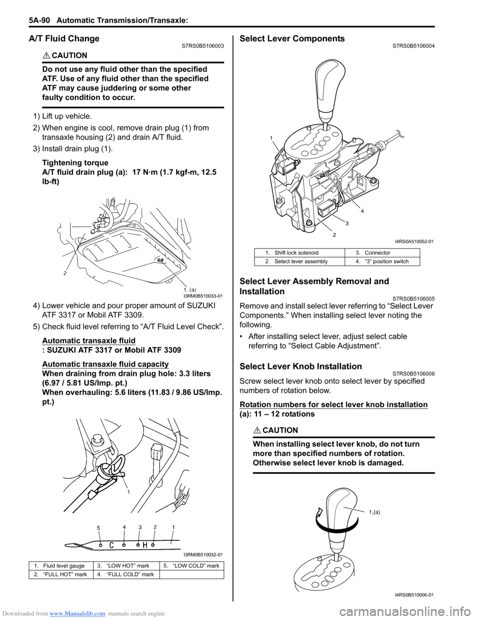
2) When engine is cool, remove drain plug (1) from
transaxle housing (2) and drain A/T fluid.
3) Install drain plug (1).
Tightening torque
A/T fluid drain plug (a): 17 N·m (1.7 kgf-m, 12.5
lb-ft)
4) Lower vehicle and pour proper amount of SUZUKI ATF 3317 or Mobil ATF 3309.
5) Check fluid level referring to “A/T Fluid Level Check”.
Automatic transaxle fluid
: SUZUKI ATF 3317 or Mobil ATF 3309
Automatic transaxle fluid capacity
When draining from drai n plug hole: 3.3 liters
(6.97 / 5.81 US/Imp. pt.)
When overhauling: 5.6 liters (11.83 / 9.86 US/Imp.
pt.)
Select Lever ComponentsS7RS0B5106004
Select Lever Assembly Removal and
Installation
S7RS0B5106005
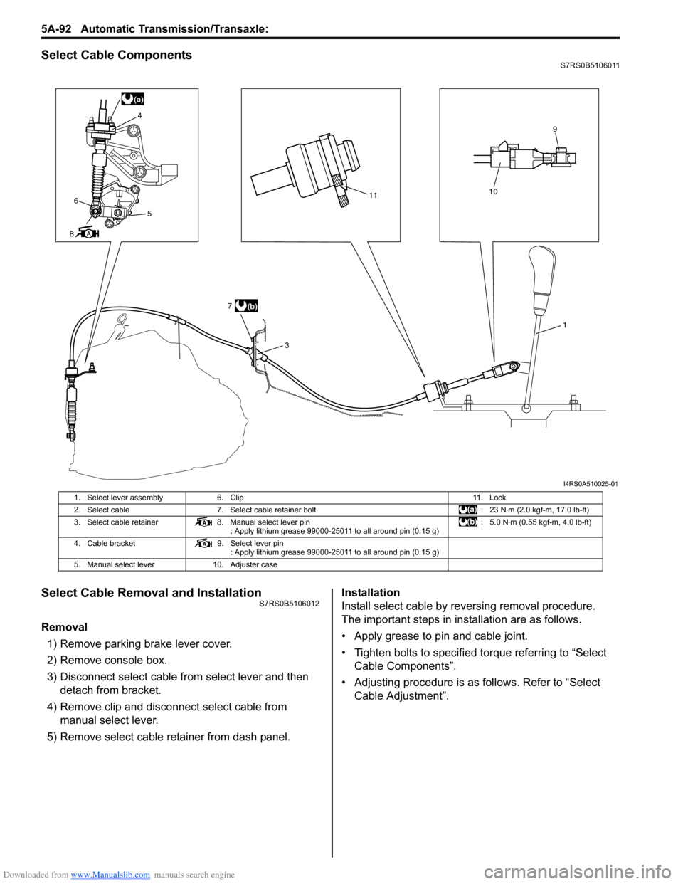
Remove and install select leve r referring to “Select Lever
Components.” When installing select lever noting the
following.
• After installing select lever, adjust select cable referring to “Select Cable Adjustment”.
Select Lever Knob InstallationS7RS0B5106006
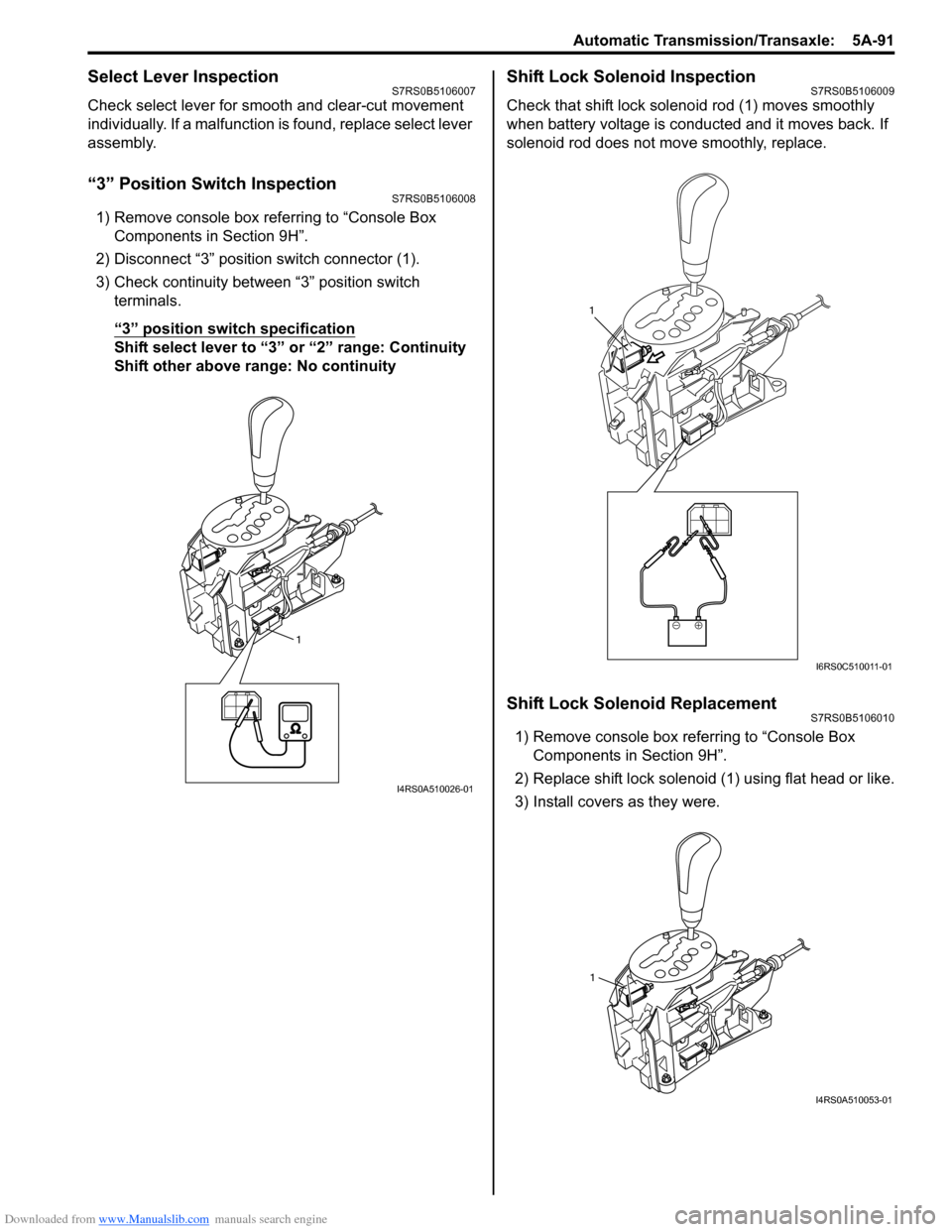
Screw select lever knob onto select lever by specified
numbers of rotation below.
Rotation numbers for select lever knob installation
(a): 11 – 12 rotations
CAUTION!
When installing select lever knob, do not turn
more than specified numbers of rotation.
Otherwise select lever knob is damaged.
1. Fluid level gauge 3. “LOW HOT” mark 5. “LOW COLD” mark
2. “FULL HOT” mark 4. “FULL COLD” mark
I3RM0B510033-01
I3RM0B510032-01
1. Shift lock solenoid 3. Connector
2. Select lever assembly 4. “3” position switch
1
23 4
I4RS0A510052-01
1,(a)
I4RS0B510006-01
Page 735 of 1496

Downloaded from www.Manualslib.com manuals search engine Automatic Transmission/Transaxle: 5A-91
Select Lever InspectionS7RS0B5106007
Check select lever for smooth and clear-cut movement
individually. If a malfunction is found, replace select lever
assembly.
“3” Position Switch InspectionS7RS0B5106008
1) Remove console box referring to “Console Box Components in Section 9H”.
2) Disconnect “3” position switch connector (1).
3) Check continuity between “3” position switch terminals.
“3” position switch specification
Shift select lever to “3 ” or “2” range: Continuity
Shift other above range: No continuity
Shift Lock Solenoid InspectionS7RS0B5106009
Check that shift lock soleno id rod (1) moves smoothly
when battery voltage is conducted and it moves back. If
solenoid rod does not move smoothly, replace.
Shift Lock Solenoid ReplacementS7RS0B5106010
1) Remove console box referring to “Console Box Components in Section 9H”.
2) Replace shift lock solenoid (1) using flat head or like.
3) Install covers as they were.
1
I4RS0A510026-01
1
I6RS0C510011-01
1
I4RS0A510053-01
Page 736 of 1496

Downloaded from www.Manualslib.com manuals search engine 5A-92 Automatic Transmission/Transaxle:
Select Cable ComponentsS7RS0B5106011
Select Cable Removal and InstallationS7RS0B5106012
Removal
1) Remove parking brake lever cover.
2) Remove console box.
3) Disconnect select cable from select lever and then detach from bracket.
4) Remove clip and disconnect select cable from manual select lever.
5) Remove select cable retainer from dash panel. Installation
Install select cable by reversing removal procedure.
The important steps in inst
allation are as follows.
• Apply grease to pin and cable joint.
• Tighten bolts to specified torque referring to “Select Cable Components”.
• Adjusting procedure is as follows. Refer to “Select Cable Adjustment”.
(a)
11
3
10
9
6
8 4
5
(b)
7
1
I4RS0A510025-01
1. Select lever assembly
6. Clip 11. Lock
2. Select cable 7. Select cable retainer bolt : 23 N⋅m (2.0 kgf-m, 17.0 lb-ft)
3. Select cable retainer 8. Manual select lever pin
: Apply lithium grease 99000-25011 to all around pin (0.15 g) :5.0 N
⋅m (0.55 kgf-m, 4.0 lb-ft)
4. Cable bracket 9. Select lever pin
: Apply lithium grease 99000-25011 to all around pin (0.15 g)
5. Manual select lever 10. Adjuster case
Page 752 of 1496
Downloaded from www.Manualslib.com manuals search engine 5A-108 Automatic Transmission/Transaxle:
Automatic Transaxle Assembly ComponentsS7RS0B5106032
I6RS0C510016-04
Page 765 of 1496
Downloaded from www.Manualslib.com manuals search engine Automatic Transmission/Transaxle: 5A-121
74) Remove manual detent spring (1).75) Remove manual shift shaft oil seal (1).
Oil Pump Assembly ComponentsS7RS0B5106034
I2RH0B510146-01I2RH0B510147-01
I2RH0B510148-01
1. Oil seal
: Apply grease 99000-25030 to oil seal lip. 5. Oil pump drive gear : Apply automatic transaxle fluid.
2. O-ring 6. Stator shaft assembly : Tightening torque
3. Oil pump body 7. Oil pump subassembly bolts : Do not reuse.
4. Oil pump driven gear
Page 768 of 1496

Downloaded from www.Manualslib.com manuals search engine 5A-124 Automatic Transmission/Transaxle:
Direct Clutch Assembly ComponentsS7RS0B5106037
Direct Clutch Assembly Preliminary CheckS7RS0B5106038
Install direct clutch assembly (1) to oil pump assembly
(2) blow in air (400 – 800 kPa, 4 – 8 kg/cm2, 57 – 113
psi) through oil hole (3) of oil pump assembly with
special tool attached on uppe r surface of direct clutch
piston, and measure piston stroke of direct clutch.
If piston stroke exceeds sp ecified value, disassemble,
inspect and replace inner parts.
Special tool
(A): 09900–20607
(B): 09900–20701
Direct clutch piston stroke
0.4 – 0.7 mm (0.016 – 0.027 in.)
I2RH0B510160-01
1. Input shaft front thrust bearing 6. Outer O-ring 11. Direct clutch retaining plate
2. Input shaft seal ring 7. Direct clutch return spring subassembly 12. Plate snap ring
3. Input shaft subassembly 8. Shaft snap ring : Apply automatic transaxle fluid.
4. Inner O-ring 9. Direct clutch separator plate : Do not reuse.
5. Direct clutch piston 10. Direct clutch disc
I2RH0B510161-01
Page 772 of 1496
Downloaded from www.Manualslib.com manuals search engine 5A-128 Automatic Transmission/Transaxle:
Forward and Reverse Clutch Assembly ComponentsS7RS0B5106041
I3RM0B510061-01
1. Forward clutch balancer8. Intermediate shaft seal ring15. Forward clutch retaining plate
2. Forward clutch return spring subassembly 9. Reverse clutch plate snap ring 16. Forward clutch disc
3. Forward clutch piston 10. Reverse clutch retaining plate 17. Forward clutch separator plate
4. Forward clutch piston O-ring 11. Reverse clutch separator plate 18. Balancer snap ring
5. Forward clutch drum 12. Reverse clutch disc : Apply automatic transaxle fluid.
6. Forward clutch drum O-ring 13. Reverse clutch cushion plate : Do not reuse.
7. Intermediate shaft subassembly 14. Forward clutch plate snap ring
Page 775 of 1496
Downloaded from www.Manualslib.com manuals search engine Automatic Transmission/Transaxle: 5A-131
Reassembly
Reverse disassembly procedure for assembly, noting the
following points.
• Before assembling, apply automatic transaxle fluid to component parts.
• Replace O-rings and seal ring with new ones.
• Do not damage forward clutch return spring subassembly and balancer (1) by pressing forward
clutch return spring subassembly passing through its
original installing position over 1.5 mm (0.059 in.).
Special tool
(A): 09926–97610
• Apply A/T fluid to forward clutch separator plates (1), discs (2) and retaining plate (3).
• Install forward clutch separator plates (1), discs (2) and retaining plate (3), then snap ring (4) to forward
clutch drum. • Install forward clutch plate snap ring so that its both
ends would be positioned in correct locations as
shown in figure.
I2RH0B510180-01
4
1
2 3
I5RW0C510062-01
[A]: Correct
[B]: Incorrect
I2RH0B510188-01