2007 SUZUKI SWIFT steering general diagnosis
[x] Cancel search: steering general diagnosisPage 872 of 1496

Downloaded from www.Manualslib.com manuals search engine 6B-1 Steering Wheel and Column:
Steeri ng
Steering Wheel and Column
Precautions
Service Precautions of Steering Wheel and
Column
S7RS0B6200001
For service precautions, refer to “Precautions on Service
and Diagnosis of Air Bag System in Section 8B”.
Service and Diagnosis
For diagnosis and servicing, refer to “Precautions on
Service and Diagnosis of Air Bag System in Section 8B”.
Disabling Air Bag System
For disabling air bag system, refer to “Disabling Air Bag
System in Section 8B”. Enabling Air Bag System
For enabling air bag system, refer to “Enabling Air Bag
System in Section 8B”.
Handling and Storage
For handling and storage, refer to “Precautions on
Handling and Storage of Air Bag System Components in
Section 8B”.
Disposal
For disposal, refer to “Prec
autions on Disposal of Air
Bag and Seat Belt Pretensioner in Section 8B”.
General Description
Steering Wheel and Column ConstructionS7RS0B6201001
This double tube type steering column has the following three important features in addition to the steering function:
• The column is energy absorbing, desig ned to compress in a front-end collision.
• The ignition switch and lock are mounted conveniently on this column.
• With the column mounted lock, the ignition and steering op erations can be locked to inhibit theft of the vehicle.
To insure the energy absorbing action, it is important th at only the specified screws, bolts and nuts be used as
designated, and that they are tightened to the specified torque. When the column assembly is removed from the
vehicle, special care must be taken in handling it. Use of a steering wheel puller or a sharp blow on the end of the
steering shaft, leaning on the assembly, or dropping the a ssembly could shear the plastic shear pins which maintain
column length and position.
The driver air bag (inflator) module is one of the supplemental restraint (air bag) system components and is mounted
to the center of the steering wheel. During certain frontal crashes, the air bag system supplements the restraint of the
driver’s and passenger’s seat belts by deploying the air b ags. The air bag (inflator) module should be handled with
care to prevent accidental deployment. When servicing, be sure to observe “Precautions on Service and Diagnosis of
Air Bag System in Section 8B”.
Page 885 of 1496

Downloaded from www.Manualslib.com manuals search engine Power Assisted Steering System: 6C-3
EPS Diagnosis General DescriptionS7RS0B6301002
The P/S system in this vehicle is controlled by the P/S control module. T he P/S control module has an on-board
diagnostic system which detects a malfunction in this system. When diagnosing troubles, be sure to have full
understanding of the outline of “On-Board Diagnostic Sy stem Description” and each item in “Precautions in
Diagnosing Troubles”, and then execute diagnosis according to “EPS System Check”.
On-Board Diagnostic System DescriptionS7RS0B6301003
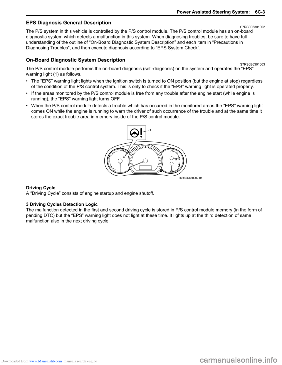
The P/S control module performs the on -board diagnosis (self-diagnosis) on the system and operates the “EPS”
warning light (1) as follows.
• The “EPS” warning light lights when the ignition switch is turned to ON position (but the engine at stop) regardless
of the condition of the P/S co ntrol system. This is only to check if the “EPS” warning light is operated properly.
• If the areas monitored by the P/S control module is free from any trouble after the engine start (while engine is
running), the “EPS” warning light turns OFF.
• When the P/S control module detects a trouble which has occurred in th e monitored areas the “EPS” warning light
comes ON while the engine is running to warn the driver of such occurrence of the trouble and at the same time it
stores the exact trouble area in memory inside of the P/S control module.
Driving Cycle
A “Driving Cycle” consists of en gine startup and engine shutoff.
3 Driving Cycles Detection Logic
The malfunction detected in the first and second driving cycl e is stored in P/S control module memory (in the form of
pending DTC) but the “EPS” wa rning light does not light at these time. It lights up at t he third detection of same
malfunction also in the next driving cycle.
1
I6RS0C630002-01
Page 1402 of 1496

Downloaded from www.Manualslib.com manuals search engine 10-ii Table of Contents
DTC P1615: ID Code Does Not Registered (Vehicle equipped with keyless start system
only) ................................................................10C-9
DTC P1616: Different Registration ID Codes (Vehicle equipped with keyless start system
only) ..............................................................10C-10
DTC P1618: CAN Communication Error (Reception Error for Keyless Start Control
Module) (Vehicle equipped with keyless
start system only) ..........................................10C-11
DTC P1621: Immobilizer Communication Line Error ......................................................10C-12
DTC P1622: EEPROM Reading / Writing Error ..............................................................10C-13
DTC P1623: Unregistered Transponder .........10C-13
DTC P1625: Immobilizer An tenna Error..........10C-14
DTC P1636: Immobilizer Information Registration Failure .......................................10C-14
DTC P1638: Immobilizer Information Mismatched ...................................................10C-15
Inspection of Immobilizer Control Module (ICM) and Its Circuit ....... ...............................10C-16
Repair Instructions ........... ...............................10C-18
Immobilizer Control Mo dule (ICM) Removal
and Installation ..............................................10C-18
Registration of the Ignition Key .......................10C-18
Procedure after ECM Replacement ................10C-18
Special Tools and Equipmen t .........................10C-19
Special Tool ....................................................10C-19
Keyless Start System ....... ......................10E-1
General Description ........................................... 10E-1
Keyless Start System Description ..................... 10E-1
Parts and Functions .......................................... 10E-2
Keyless Engine Start Function .......................... 10E-3
Door Lock Function of Keyless Start System .... 10E-4
Operation Area of Remote Controller................ 10E-5
Alarm Function .................................................. 10E-6
CAN Communication System Description......... 10E-6
Schematic and Routing Diagram ...................... 10E-7 Keyless Start System El ectric Wiring Circuit
Diagram .......................................................... 10E-7
Diagnostic Information and Procedures .......... 10E-8 Precautions in Diagnosing Troubles ................. 10E-8
Self-Diagnosis Function .................................... 10E-8
Keyless Start System Diagn osis Introduction ... 10E-8 Keyless Start System Chec
k ............................. 10E-8
Customer Questionnaire (E xample) .................. 10E-9
Key Indicator Lamp Check .............................. 10E-10
DTC Check...................................................... 10E-10
DTC Table ....................................................... 10E-11
DTC Clearance ............................................... 10E-12
Keyless Start System Symp tom Diagnosis ..... 10E-12
Keyless Start System Operation Inspection .... 10E-13
Door Lock Operation (Keyless Start System) . 10E-14
Inspection of Keyless Start Control Module and Its Circuits .............................................. 10E-14
No DTC Detection After Performing DTC Check ............................................................ 10E-18
Key Indicator Lamp Circuit Check (Key indicator lamp doesn’t light when ignition
knob switch is pushed.) ................................. 10E-20
Keyless Start Control Module Power and Ground Circuit Check .................................... 10E-22
DTC No. 11: Communi cation Error with
Steering Lock Unit ......................................... 10E-23
DTC No. 13 / No. 14: Release Signal Error from Steering Lock Unit / Steering Lock Unit
Malfunction .................................................... 10E-24
DTC No. 21 / No. 22: Internal Error of Keyless Start Control Module (EEPROM reading
error) / (EEPROM writing error) ............ ........ 10E-24
DTC No. 31: Lost Commun ication with BCM .. 10E-25
DTC No. 33: Control Module Communication
Bus Off .......................................................... 10E-27
DTC No. 51 / No. 52 / No. 53: Driver Side / Passenger Side / Rear End Door Request
Switch Failure................................................ 10E-28
Repair Instructions ............ .............................. 10E-30
Antennas and Request Switches Removal and Installation .............................................. 10E-30
Front Door (Driver and Passenger Side), Rear End Door Request Switch Inspection............ 10E-31
Steering Lock Unit Removal and Installation .. 10E-31
Steering Lock Unit Inspection ......................... 10E-31
Front Door Lock Switch In spection ................. 10E-31
Keyless Start Control Module Removal and Installation ..................................................... 10E-32
Remote Controller Inspection.......................... 10E-32
Replacement of Remote Controller Battery .... 10E-32
Registration Procedure for Remote Controller
ID Code ......................................................... 10E-33