Page 322 of 1496

Downloaded from www.Manualslib.com manuals search engine 1D-37 Engine Mechanical:
Valves and Cylinder Head Disassembly and
Assembly
S7RS0B1406025
Disassembly1) For ease in servicing cylinder head, remove intake manifold, injectors, exhaust manifold from cylinder
head.
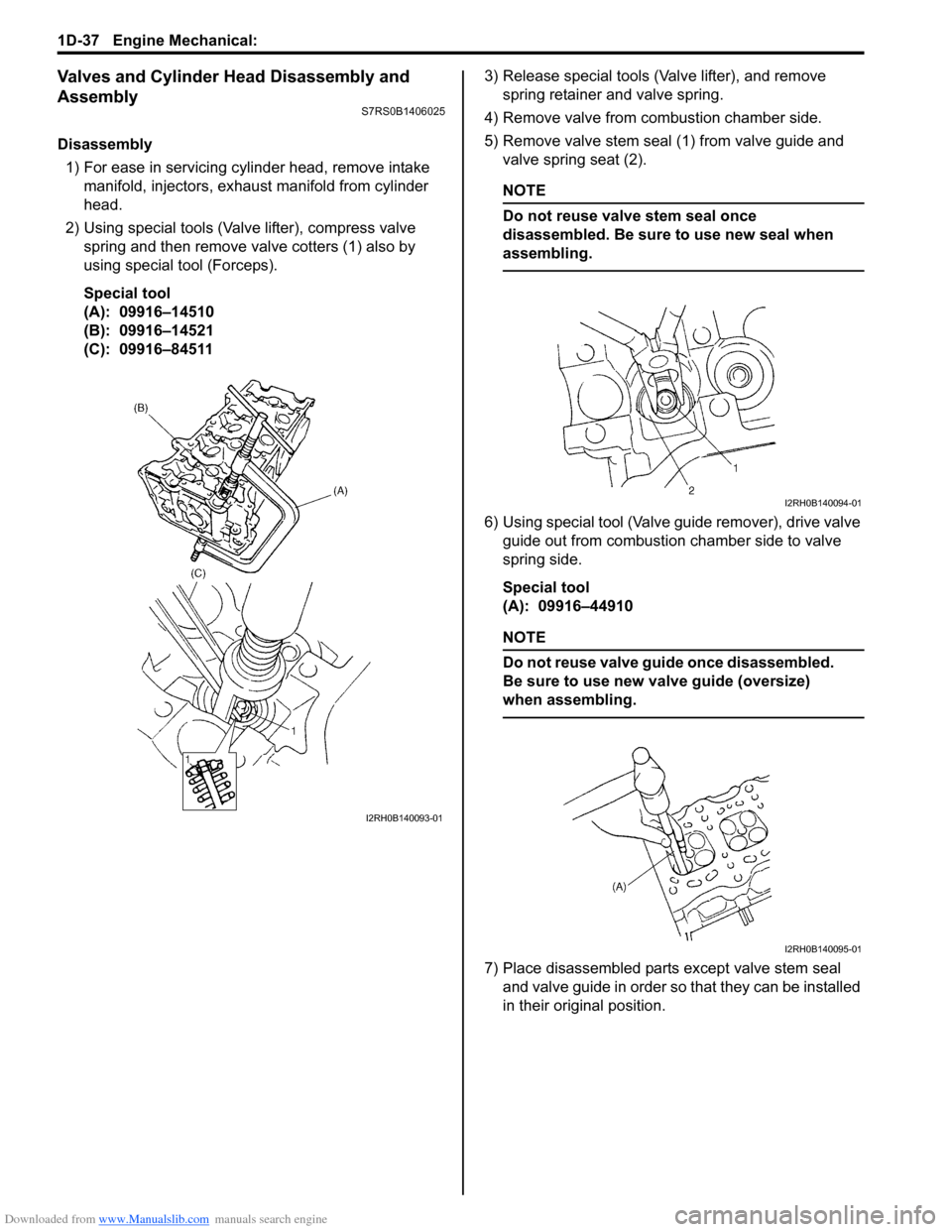
2) Using special tools (Val ve lifter), compress valve
spring and then remove valve cotters (1) also by
using special tool (Forceps).
Special tool
(A): 09916–14510
(B): 09916–14521
(C): 09916–84511 3) Release special tools (Valve lifter), and remove
spring retainer and valve spring.
4) Remove valve from combustion chamber side.
5) Remove valve stem seal (1) from valve guide and valve spring seat (2).
NOTE
Do not reuse valve stem seal once
disassembled. Be sure to use new seal when
assembling.
6) Using special tool (Valve guide remover), drive valve guide out from combustion chamber side to valve
spring side.
Special tool
(A): 09916–44910
NOTE
Do not reuse valve guide once disassembled.
Be sure to use new va lve guide (oversize)
when assembling.
7) Place disassembled parts except valve stem seal
and valve guide in order so that they can be installed
in their original position.
I2RH0B140093-01
I2RH0B140094-01
I2RH0B140095-01
Page 323 of 1496

Downloaded from www.Manualslib.com manuals search engine Engine Mechanical: 1D-38
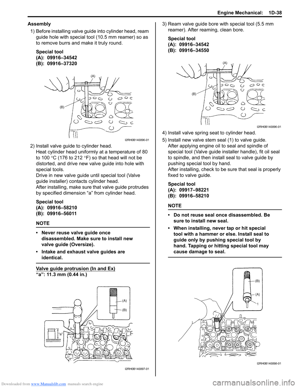
Assembly1) Before installing valve guide into cylinder head, ream
guide hole with special tool (10.5 mm reamer) so as
to remove burrs and make it truly round.
Special tool
(A): 09916–34542
(B): 09916–37320
2) Install valve guide to cylinder head. Heat cylinder head uniformly at a temperature of 80
to 100 °C (176 to 212 °F) so that head will not be
distorted, and drive new valve guide into hole with
special tools.
Drive in new valve guide until special tool (Valve
guide installer) contacts cylinder head.
After installing, ma ke sure that valve guide pr otrudes
by specified dimension “a” from cylinder head.
Special tool
(A): 09916–58210
(B): 09916–56011
NOTE
• Never reuse valve guide once disassembled. Make sure to install new
valve guide (Oversize).
• Intake and exhaust valve guides are identical.
Valve guide protrusion (In and Ex)
“a”: 11.3 mm (0.44 in.) 3) Ream valve guide bore with special tool (5.5 mm
reamer). After reaming, clean bore.
Special tool
(A): 09916–34542
(B): 09916–34550
4) Install valve spring seat to cylinder head.
5) Install new valve stem seal (1) to valve guide. After applying engine oil to seal and spindle of
special tool (Valve guide installer handle), fit oil seal
to spindle, and then install seal to valve guide by
pushing special tool by hand.
After installing, check to be sure that seal is properly
fixed to valve guide.
Special tool
(A): 09917–98221
(B): 09916–58210
NOTE
• Do not reuse seal once disassembled. Be sure to install new seal.
• When installing, never tap or hit special tool with a hammer or else. Install seal to
guide only by pushing special tool by
hand. Tapping or hitting special tool may
cause damage to seal.
I2RH0B140096-01
I2RH0B140097-01
I2RH0B140096-01
I2RH0B140098-01
Page 324 of 1496

Downloaded from www.Manualslib.com manuals search engine 1D-39 Engine Mechanical:
6) Install valve to valve guide.Before installing valve to valve guide, apply engine
oil to stem seal, valve guide bore and valve stem.
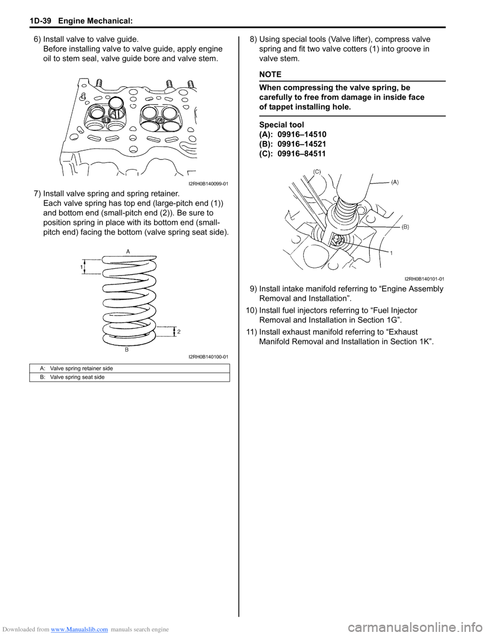
7) Install valve spring and spring retainer. Each valve spring has top end (large-pitch end (1))
and bottom end (small-pitch end (2)). Be sure to
position spring in place with its bottom end (small-
pitch end) facing the bottom (valve spring seat side). 8) Using special tools (Val
ve lifter), compress valve
spring and fit two valve cotters (1) into groove in
valve stem.
NOTE
When compressing the valve spring, be
carefully to free from damage in inside face
of tappet installing hole.
Special tool
(A): 09916–14510
(B): 09916–14521
(C): 09916–84511
9) Install intake manifold referring to “Engine Assembly Removal and Installation”.
10) Install fuel injectors referring to “Fuel Injector Removal and Installati on in Section 1G”.
11) Install exhaust manifold referring to “Exhaust Manifold Removal and Inst allation in Section 1K”.
A: Valve spring retainer side
B: Valve spring seat side
I2RH0B140099-01
I2RH0B140100-01
I2RH0B140101-01
Page 351 of 1496

Downloaded from www.Manualslib.com manuals search engine Engine Mechanical: 1D-66
Special Tools and Equipment
Recommended Service MaterialS7RS0B1408001
NOTE
Required service material is also described in the following.
“Timing Chain Cover Components”
“Timing Chain and Chain Tensioner Components”
“Camshaft, Tappet and Shim Components”
“Valves and Cylinder Head Components”
“Pistons, Piston Rings, Connecting Rods and Cylinders Components”
“Main Bearings, Crankshaft and Cylinder Block Components”
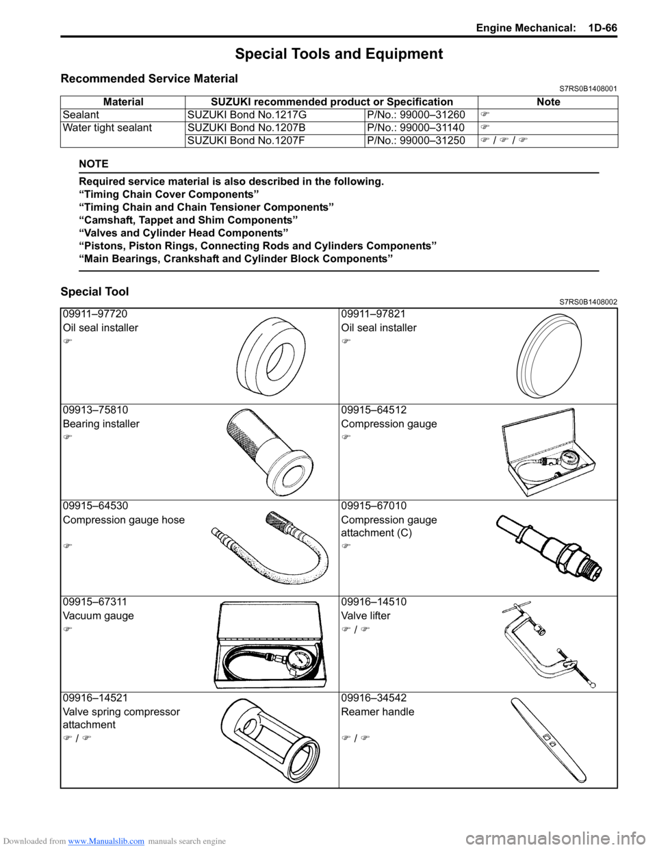
Special ToolS7RS0B1408002
Material SUZUKI recommended product or Specification Note
Sealant SUZUKI Bond No.1217G P/No.: 99000–31260�)
Water tight sealant SUZUKI Bond No.1207B P/No.: 99000–31140�)
SUZUKI Bond No.1207F P/No.: 99000–31250�) / �) / �)
09911–97720 09911–97821
Oil seal installer Oil seal installer
�)�)
09913–75810 09915–64512
Bearing installer Compression gauge
�)�)
09915–64530 09915–67010
Compression gauge hose Compression gauge
attachment (C)
�)�)
09915–67311 09916–14510
Vacuum gauge Valve lifter
�)�) / �)
09916–14521 09916–34542
Valve spring compressor
attachment Reamer handle
�) / �)�) / �)
Page 354 of 1496

Downloaded from www.Manualslib.com manuals search engine 1E-2 Engine Lubrication System:
Diagnostic Information and Procedures
Oil Pressure CheckS7RS0B1504001
WARNING!
To avoid danger of being burned, do not
touch exhaust system when it is still hot.
NOTE
Prior to checking oil pressure, check the
following.
• Oil level in oil pan
If oil level is low, add oil up to Full level
mark (hole) (1) on oil level gauge referring
to “Engine Oil and Filter Change in Section
0B”.
• Oil quality If oil is discolored or deteriorated, change
it. For particular oil to be used, refer to
“Engine Oil and Filter Change in Section
0B”.
• Oil leaks If leak is found, repair it.
1) Remove front bumper referring to “Front Bumper and Rear Bumper Components in Section 9K”.
2) Remove engine front cover (1).
3) Disconnect oil pressure switch coupler (1).
4) Remove oil pressure swit ch (2) from cylinder block.
5) Install special tools (oil pressure gauge) to vacated threaded hole of oil pressure switch.
Special tool
(A): 09915–77310
(B): 09915–78211
2. Low level mark (hole)
I2RH0B150002-01
1
I4RS0A150001-01
I2RH0B150003-01
I2RH0B150004-01
Page 363 of 1496

Downloaded from www.Manualslib.com manuals search engine Engine Lubrication System: 1E-11
Specifications
Tightening Torque SpecificationsS7RS0B1507001
NOTE
The specified tightening torque is also described in the following.
“Heat Exchanger Components”
“Oil Pan and Oil Pump Strainer Components”
“Oil Pump Components”
Reference:
For the tightening torque of fastener not specified in this section, refer to “Fasteners Information in Section 0A”.
Special Tools and Equipment
Recommended Service MaterialS7RS0B1508001
NOTE
Required service material is also described in the following.
“Heat Exchanger Components”
“Oil Pan and Oil Pump Strainer Components”
“Oil Pump Components”
Special ToolS7RS0B1508002
Fastening part Tightening torque
Note
N ⋅mkgf-mlb-ft
Oil pressure switch 13 1.3 9.5 �)
Heat exchanger stand bolt 22 2.2 16.0 �)
Oil pump strainer bolt 11 1.1 8.0 �)
Oil pump strainer bracket bolt 11 1.1 8.0 �)
Oil pan bolt (M6) 11 1.1 8.0 �)
Oil pan bolt (M10) 55 5.5 40.0 �)
Oil pan nut 11 1.1 8.0 �)
Oil pan drain plug 35 3.5 25.5 �)
Transaxle stiffener bolt 55 5.5 40.0 �)
Oil pump rotor plate bolt 11 1.1 8.0 �)
MaterialSUZUKI recommended product or Specification Note
Sealant SUZUKI Bond No.1217G P/No.: 99000–31260�)
09915–77310 09915–78211
Oil pressure gauge (0-10kg/
cm2) Oil pressure gauge
attachment
�)�)
Page 375 of 1496
Downloaded from www.Manualslib.com manuals search engine Engine Cooling System: 1F-12
Specifications
Tightening Torque SpecificationsS7RS0B1607001
NOTE
The specified tightening torque is also described in the following.
“Cooling System Components”
Reference:
For the tightening torque of fastener not specified in this section, refer to “Fasteners Information in Section 0A”.
Special Tools and Equipment
Recommended Service MaterialS7RS0B1608001
Fastening part Tightening torque
Note
N ⋅mkgf-mlb-ft
Water pump bolt and nut 25 2.5 18.0 �)
MaterialSUZUKI recommended product or Specification Note
Water tight sealant SUZUKI Bond No.1207F P/No.: 99000–31250�)
Page 377 of 1496

Downloaded from www.Manualslib.com manuals search engine Fuel System: 1G-2
Fuel Pump DescriptionS7RS0B1701003
The fuel pump (1) is an in-tank type electric pump.
Incorporated in the pump assembly are;
a fuel filter (2) and a fuel pressure regulator (3) are
included and a fuel level gauge (4) is attached.
Addition of the fuel pressure regulator to the fuel pump
makes it possible to mainta in the fuel pressure at
constant level and ECM controls compensation for
variation in the intake manifold pressure.
Schematic and Routing Diagram
Fuel Delivery System DiagramS7RS0B1702001
Diagnostic Information and Procedures
Fuel Pressure InspectionS7RS0B1704001
WARNING!
Before starting the following procedure, be
sure to observe “Precautions on Fuel System
Service” in order to reduce the risk or fire
and personal injury.
1) Relieve fuel pressure in fuel feed line referring to
“Fuel Pressure Relief Procedure”.
2) Disconnect fuel feed hose from fuel delivery pipe.
3) Connect special tools and hose between fuel feed hose (1) and fuel delivery pipe as shown in figure,
and clamp hoses securely in order to ensure that no
leaks occur during checking.
Special tool
(A): 09912–58442
(B): 09912–58432
(C): 09912–58490
1
3
2
4
I6RS0C170001-01
4
6 7
8
12
2 3
11
10
5
1
9
I6RS0C170002-01
1. Fuel tank
5. Fuel injector9. EVAP canister
2. Fuel pump 6. Fuel feed line10. Fuel filter
3. Fuel pressure regulator 7. Fuel vapor line 11. Main fuel level sensor
4. Delivery pipe 8. Intake manifold12. EVAP canister purge valve
1
(C) (B)
(A)
I3RM0A170004-01