2007 SUZUKI SWIFT set time
[x] Cancel search: set timePage 242 of 1496
Downloaded from www.Manualslib.com manuals search engine 1A-192 Engine General Information and Diagnosis:
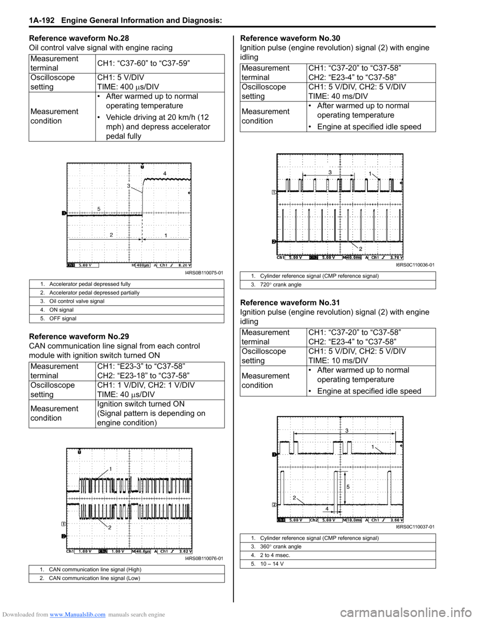
Reference waveform No.28
Oil control valve signal with engine racing
Reference waveform No.29
CAN communication line signal from each control
module with ignition switch turned ONReference waveform No.30
Ignition pulse (engine revolution) signal (2) with engine
idling
Reference waveform No.31
Ignition pulse (engine revolution) signal (2) with engine
idling
Measurement
terminal
CH1: “C37-60” to “C37-59”
Oscilloscope
setting CH1: 5 V/DIV
TIME: 400
µs/DIV
Measurement
condition • After warmed up to normal
operating temperature
• Vehicle driving at 20 km/h (12 mph) and depress accelerator
pedal fully
1. Accelerator pedal depressed fully
2. Accelerator pedal depressed partially
3. Oil control valve signal
4. ON signal
5. OFF signal
Measurement
terminal CH1: “E23-3” to “C37-58”
CH2: “E23-18” to “C37-58”
Oscilloscope
setting CH1: 1 V/DIV, CH2: 1 V/DIV
TIME: 40
µs/DIV
Measurement
condition Ignition switch turned ON
(Signal pattern is depending on
engine condition)
1. CAN communication line signal (High)
2. CAN communication line signal (Low)
I4RS0B110075-01
I4RS0B110076-01
Measurement
terminal
CH1: “C37-20” to “C37-58”
CH2: “E23-4” to “C37-58”
Oscilloscope
setting CH1: 5 V/DIV, CH2: 5 V/DIV
TIME: 40 ms/DIV
Measurement
condition • After warmed up to normal
operating temperature
• Engine at specified idle speed
1. Cylinder reference signal (CMP reference signal)
3. 720 ° crank angle
Measurement
terminal CH1: “C37-20” to “C37-58”
CH2: “E23-4” to “C37-58”
Oscilloscope
setting CH1: 5 V/DIV, CH2: 5 V/DIV
TIME: 10 ms/DIV
Measurement
condition • After warmed up to normal
operating temperature
• Engine at specified idle speed
1. Cylinder reference signal (CMP reference signal)
3. 360 ° crank angle
4. 2 to 4 msec.
5. 10 – 14 V
I6RS0C110036-01
I6RS0C110037-01
Page 243 of 1496
Downloaded from www.Manualslib.com manuals search engine Engine General Information and Diagnosis: 1A-193
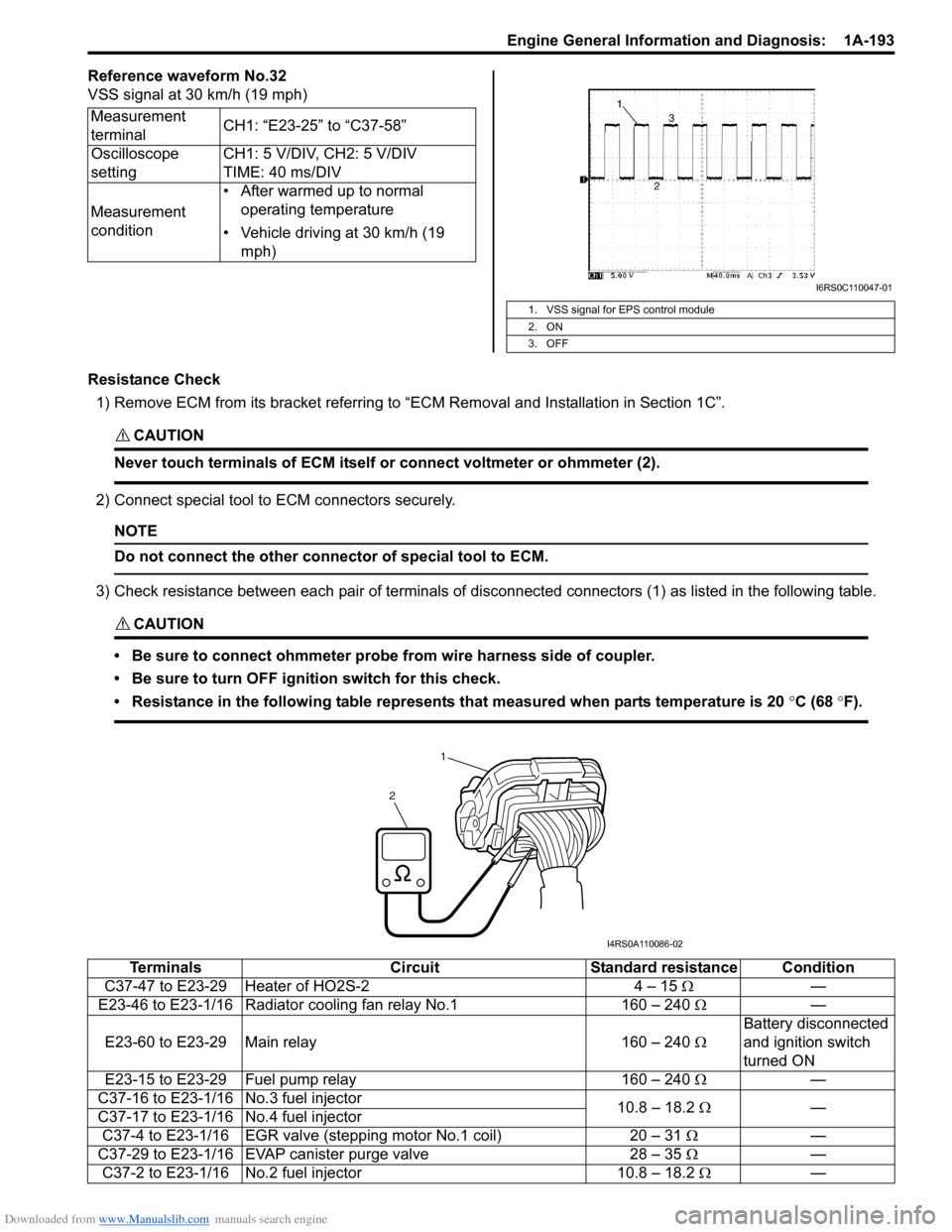
Reference waveform No.32
VSS signal at 30 km/h (19 mph)
Resistance Check1) Remove ECM from its bracket referring to “ECM Removal and Installation in Section 1C”.
CAUTION!
Never touch terminals of ECM itself or connect voltmeter or ohmmeter (2).
2) Connect special tool to ECM connectors securely.
NOTE
Do not connect the other connector of special tool to ECM.
3) Check resistance between each pair of terminals of disconnected connectors (1) as listed in the following table.
CAUTION!
• Be sure to connect ohmmeter probe from wire harness side of coupler.
• Be sure to turn OFF ignition switch for this check.
• Resistance in the following table represents that measured when parts temperature is 20 °C (68 °F).
Measurement
terminal CH1: “E23-25” to “C37-58”
Oscilloscope
setting CH1: 5 V/DIV, CH2: 5 V/DIV
TIME: 40 ms/DIV
Measurement
condition • After warmed up to normal
operating temperature
• Vehicle driving at 30 km/h (19 mph)
1. VSS signal for EPS control module
2. ON
3. OFF
I6RS0C110047-01
1
2
I4RS0A110086-02
Terminals CircuitStandard resistance Condition
C37-47 to E23-29 Heater of HO2S-2 4 – 15 Ω—
E23-46 to E23-1/16 Radiator cooling fan relay No.1 160 – 240 Ω —
E23-60 to E23-29 Main relay 160 – 240 ΩBattery disconnected
and ignition switch
turned ON
E23-15 to E23-29 Fuel pump relay 160 – 240 Ω —
C37-16 to E23-1/16 No.3 fuel injector 10.8 – 18.2 Ω —
C37-17 to E23-1/16 No.4 fuel injector
C37-4 to E23-1/16 EGR valve (st epping motor No.1 coil) 20 – 31 Ω —
C37-29 to E23-1/16 EVAP canister purge valve 28 – 35 Ω —
C37-2 to E23-1/16 No.2 fuel injector 10.8 – 18.2 Ω—
Page 382 of 1496

Downloaded from www.Manualslib.com manuals search engine 1G-7 Fuel System:
Fuel Pressure Relief ProcedureS7RS0B1706003
CAUTION!
This work must not be done when engine is
hot. If done so, it may cause adverse effect to
catalyst.
NOTE
If ECM detects DTC(s) after servicing, clear
DTC(s) referring to “DTC Clearance in
Section 1A”.
1) Make sure that engine is cold.
2) Shift transaxle gear shift lever in “Neutral” (shift select lever in “P” range for A/T model), set parking
brake and block drive wheels.
3) Remove relay / fuse box cover.
4) Disconnect fuel pump relay (1) from relay / fuse box (2).
5) Remove fuel filter cap in order to release fuel vapor pressure in fuel tank, and then reinstall it.
6) Start engine and run it until engine stops for lack of fuel. Repeat cranking engine 2 – 3 times for about 3
seconds each time in order to dissipate fuel pressure
in lines. Fuel connections are now safe for servicing.
7) After servicing, connect fuel pump relay (1) to relay / fuse box and install re lay / fuse box cover.
Fuel Leakage Check ProcedureS7RS0B1706004
After performing any service on fuel system, check to
make sure that there are no fuel leakages as follows.
1) Turn ON ignition switch for 3 seconds (to operate fuel pump) and then turn it OFF.
Repeat this (ON and OFF) 3 or 4 times and apply
fuel pressure to fuel line until fuel pressure is felt by
hand placed on fuel feed hose.
2) In this state, check to see that there are no fuel leakages from any part of fuel system.
Fuel Lines On-Vehicle InspectionS7RS0B1706005
CAUTION!
Due to the fact that fuel feed line (1) is under
high pressure, use special care when
servicing it.
Visually inspect fuel lines for evidence of fuel leakage,
hose crack and deterioration or damage.
Make sure all cl amps are secure.
Replace parts as needed.
Fuel Pipe Removal and InstallationS7RS0B1706006
WARNING!
Before starting the following procedure, be
sure to observe “Precautions on Fuel System
Service” in order to reduce the risk or fire
and personal injury.
Removal
1) Relieve fuel pressure in fuel feed line according to “Fuel Pressure Relief Procedure”.
2) Disconnect negative cable at battery.
3) Disconnect fuel pipe joint and fuel hose (3) from fuel pipe (2) at the front and rear of each fuel pipe
referring to “Fuel Hose Disconnecting and
Reconnecting”.
4) Mark the location of clamps (1) on fuel pipes (2), so that the clamps can be reinstalled to where they
were.
5) Remove pipes (2) with clamp (1) from vehicle.
6) Remove clamp (1) from pipes (2).
1
I4RS0A170004-01
1
I4RS0A170005-01
2
13
I4RS0A170020-01
Page 415 of 1496

Downloaded from www.Manualslib.com manuals search engine Charging System: 1J-5
Generator Test (Undercharged Battery Check)S7RS0B1A04003
This condition, as evidenced by slow cranking or
indicator clear with dark or light yellow dot can be
caused by one or more of the following conditions even
though indicator lamp may be operating normal.
The following procedure also applies to cars with
voltmeter and ammeter.1) Make sure that undercharged condition has not been caused by accessories left on for extended period of
time.
2) Check drive belt for proper tension.
3) If battery defect is suspected, refer to “Battery Description”.
4) Inspect wiring for defects. Check all connections for tightness and cleanliness, battery cable connections
at battery, starting motor, ignition ground cable and
no “C” terminal circuit at ground.
5) Connect switch (6), load (5), battery (4), voltmeter (3) and ammeter (2) to generator (1) as shown in
figure.
Voltmeter: Set between generator “B” terminal
and ground.
Ammeter: Set between generator “B” terminal
and battery (+) terminal.
NOTE
Use fully charged battery.
6) Measure current and voltage.
No-Load Check 1) Run engine from idling up to 2000 rpm and read meters.
NOTE
Turn off switches of all accessories (wiper,
heater etc.).
Specification for undercharged battery (No-load
check)
Current: 10 A
Voltage: 14.2 – 14.8 V (at 20 °C, 68 °F)
NOTE
Consideration should be taken that voltage
will differ somewhat with regulator case
temperature as shown in figure.
2) Using service wire, ground “C” terminal (1) of
generator.
3) Measure voltage between “B” terminal of generator and body ground.
Voltage: 12.5 – 13.1 V (at 20 °C, 68 °F)
• If voltage is higher than standard value
If voltage is higher than standard value, check ground
of brushes.
If brushes are not grounded, replace IC regulator.
If voltage is lower than standard value, proceed to the
following check.
Load Check 1) Run engine at 2000 rpm and turn on head light and blower motor.
2) Measure current. If measure current is less than 30 A, repair or
replace generator.
IYSQ011A0007-01
[A]: Regulated voltage (V)
[B]: Heat sink temperature ( °C)
16.0
15.5
15.0
14.5
14.0
13.5
13.0
-30 0 20
[A]
[B]
68
22120 (˚C)
248 (˚F)
(V)
I6RS0B1A1002-01
I5JB0A1A0011-01
Page 435 of 1496
Downloaded from www.Manualslib.com manuals search engine Front Suspension: 2B-2
Front Wheel Alignment ConstructionS7RS0B2201002
Among factors for front wheel alignment, only toe setting
can be adjusted. Camber and caster are not adjustable.
Therefore, should camber or caster be out of
specification due to the damage caused by hazardous
road conditions or collision, whether the damage is in
body or in suspension should be determined and
damaged body should be repaired or damaged
suspension should be replaced.
Preliminary Checks Prior to Adjustment Front Wheel
Alignment
Steering and vibration complaints are not always the
result of improper wheel alignment. An additional item to
be checked is the possibility of tire lead due to worn or
improperly manufactured tires. “Lead” is the vehicle
deviation from a straight path on a level road without
hand pressure on the steering wheel. Refer to “Radial
Tire Lead / Pull Description in Section 2D” in order to
determine if the vehicle has a tire lead problem. Before
making any adjustment affecting wheel alignment, the
following checks and inspections should be made to
ensure correctness of alignment readings and alignment
adjustments:
• Check all tires for proper inflation pressures and approximately the same tread wear. • Check for loose of ball join
ts. Check tie-rod ends; if
excessive looseness is noted, it must be corrected
before adjusting.
• Check for run-out of wheels and tires.
• Check vehicle trim heights; if it is out of limit and a
correction is needed, it must be done before adjusting
toe.
• Check for loose of suspension control arms.
• Check for loose or missin g stabilizer bar attachments.
• Consideration must be given to excess loads, such as
tool boxes. If this excess load is normally carried in
vehicle, it should remain in vehicle during alignment
checks.
• Consider condition of equipment being used to check alignment and follow manufa cturer’s instructions.
• Regardless of equipment used to check alignment, vehicle must be placed on a level surface.
NOTE
To prevent possible incorrect reading of toe,
camber or caster, vehicle front and rear end
must be moved up and down a few times
before inspection.
Repair Instructions
Front Wheel Alignment Inspection and
Adjustment
S7RS0B2206001
Toe Inspection and Adjustment
Preparation for toe inspection and adjustment.
• Place vehicle in unloaded state on level surface.
• Set steering wheel in straight state.
• Check that inflation pressure of each tire is adjusted properly and wheel is free from deflection.
• Check that each suspension part is free from bend, dent, wear or damage in any other form.
• Check that ground clearance at the right and left is just about the same.
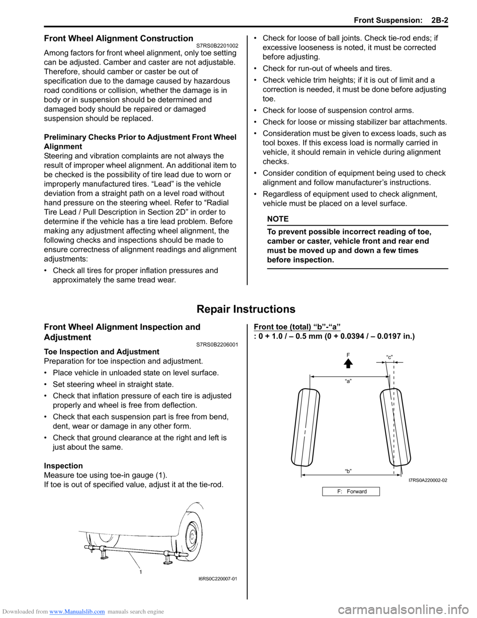
Inspection
Measure toe using toe-in gauge (1).
If toe is out of specified value, adjust it at the tie-rod. Front toe (total) “b”-“a”
: 0 + 1.0 / – 0.5 mm (0 + 0.0394 / – 0.0197 in.)
I6RS0C220007-01
F: Forward
“a”
“c”
“b” F
I7RS0A220002-02
Page 518 of 1496
Downloaded from www.Manualslib.com manuals search engine 4B-2 Front Brakes:
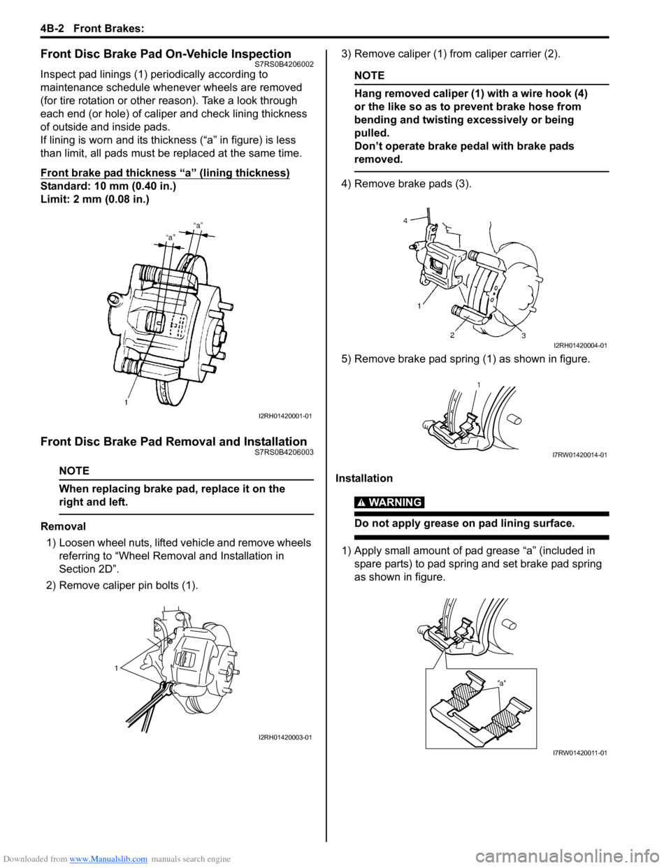
Front Disc Brake Pad On-Vehicle InspectionS7RS0B4206002
Inspect pad linings (1) periodically according to
maintenance schedule whenever wheels are removed
(for tire rotation or other reason). Take a look through
each end (or hole) of caliper and check lining thickness
of outside and inside pads.
If lining is worn and its thic kness (“a” in figure) is less
than limit, all pads must be replaced at the same time.
Front brake pad thickness “a” (lining thickness)
Standard: 10 mm (0.40 in.)
Limit: 2 mm (0.08 in.)
Front Disc Brake Pad Removal and InstallationS7RS0B4206003
NOTE
When replacing brake pad, replace it on the
right and left.
Removal
1) Loosen wheel nuts, lifted vehicle and remove wheels referring to “Wheel Remova l and Installation in
Section 2D”.
2) Remove caliper pin bolts (1). 3) Remove caliper (1) from caliper carrier (2).
NOTE
Hang removed caliper (1) with a wire hook (4)
or the like so as to prevent brake hose from
bending and twisting excessively or being
pulled.
Don’t operate brake pedal with brake pads
removed.
4) Remove brake pads (3).
5) Remove brake pad spring (1) as shown in figure.
Installation
WARNING!
Do not apply grease on pad lining surface.
1) Apply small amount of pad grease “a” (included in spare parts) to pad spring and set brake pad spring
as shown in figure.
I2RH01420001-01
1
I2RH01420003-01
I2RH01420004-01
1
I7RW01420014-01
"a"
I7RW01420011-01
Page 567 of 1496
Downloaded from www.Manualslib.com manuals search engine ABS: 4E-28
Repair Instructions
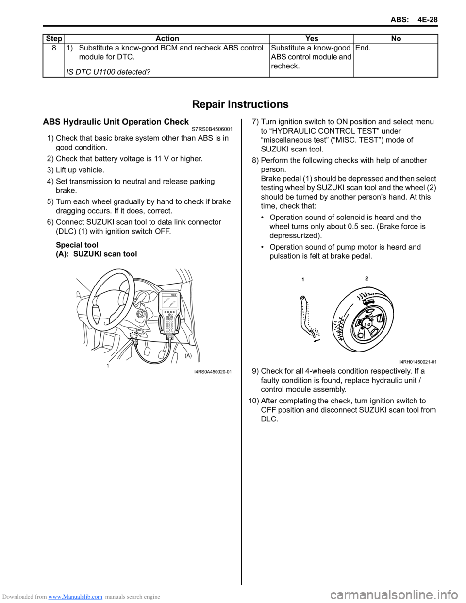
ABS Hydraulic Unit Operation CheckS7RS0B4506001
1) Check that basic brake system other than ABS is in good condition.
2) Check that battery voltage is 11 V or higher.
3) Lift up vehicle.
4) Set transmission to neutral and release parking brake.
5) Turn each wheel gradually by hand to check if brake dragging occurs. If it does, correct.
6) Connect SUZUKI scan tool to data link connector (DLC) (1) with ignition switch OFF.
Special tool
(A): SUZUKI scan tool 7) Turn ignition switch to ON position and select menu
to “HYDRAULIC CONTROL TEST” under
“miscellaneous test” (“MISC. TEST”) mode of
SUZUKI scan tool.
8) Perform the following checks with help of another person.
Brake pedal (1) should be depressed and then select
testing wheel by SUZUKI scan tool and the wheel (2)
should be turned by another person’s hand. At this
time, check that:
• Operation sound of solenoid is heard and the wheel turns only about 0.5 sec. (Brake force is
depressurized).
• Operation sound of pump motor is heard and pulsation is felt at brake pedal.
9) Check for all 4-wheels co ndition respectively. If a
faulty condition is found, replace hydraulic unit /
control module assembly.
10) After completing the check, turn ignition switch to OFF position and disconnect SUZUKI scan tool from
DLC.
8 1) Substitute a know-good BCM and recheck ABS control
module for DTC.
IS DTC U1100 detected? Substitute a know-good
ABS control module and
recheck.
End.
Step Action Yes No
1 (A)I4RS0A450020-01
I4RH01450021-01
Page 570 of 1496
Downloaded from www.Manualslib.com manuals search engine 4E-31 ABS:
2) Bleed air from brake system referring to “Air Bleeding of Brake System in Section 4A”.
3) Check each installed part for fluid leakage and perform “ABS Hydraulic Un it Operation Check”.
NOTE
For new ABS hydraulic unit / control module
assembly, if “ABS Hydraulic Unit Operation
Check” has not been performed, ABS
warning light may flash when ignition switch
is turned ON position.
Accordingly preform “ABS Hydraulic Unit
Operation Check” to stop flashing of ABS
warning light.
Front / Rear Wheel Speed Sensor On-Vehicle
Inspection
S7RS0B4506005
Output Voltage Inspection
1) Disconnect negative cable from battery.
2) Hoist vehicle a little.
3) Disconnect wheel speed sensor connector.
4) Disconnect wheel speed grommet from vehicle body.
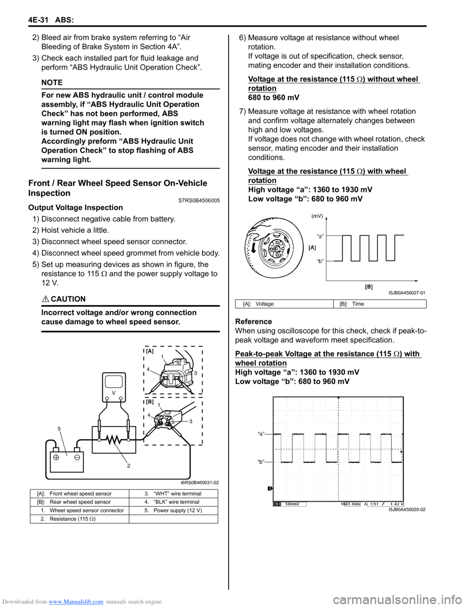
5) Set up measuring devices as shown in figure, the resistance to 115 Ω and the power supply voltage to
12 V.
CAUTION!
Incorrect voltage and/or wrong connection
cause damage to wheel speed sensor.
6) Measure voltage at resistance without wheel rotation.
If voltage is out of specification, check sensor,
mating encoder and their installation conditions.
Voltage at the resistance (115
Ω) without wheel
rotation
680 to 960 mV
7) Measure voltage at resistance with wheel rotation and confirm voltage alternately changes between
high and low voltages.
If voltage does not change with wheel rotation, check
sensor, mating encoder and their installation
conditions.
Voltage at the resistance (115
Ω) with wheel
rotation
High voltage “a”: 1360 to 1930 mV
Low voltage “b”: 680 to 960 mV
Reference
When using oscilloscope for this check, check if peak-to-
peak voltage and waveform meet specification.
Peak-to-peak Voltage at the resistance (115
Ω) with
wheel rotation
High voltage “a”: 1360 to 1930 mV
Low voltage “b”: 680 to 960 mV
[A]: Front wheel speed sensor 3. “WHT” wire terminal
[B]: Rear wheel speed sensor 4. “BLK” wire terminal
1. Wheel speed sensor connector 5. Power supply (12 V)
2. Resistance (115 Ω )
V
2
5
41
3
43
1
[A]
[B]
I6RS0B460031-02
[A]: Voltage [B]: Time
I5JB0A450027-01
I5JB0A450028-02