Page 849 of 1496

Downloaded from www.Manualslib.com manuals search engine Manual Transmission/Transaxle: 5B-35
6) Hold differential assembly with soft jawed vise (3),
install final gear (2) as shown in figure and then
tighten bolts (1) to specified torque.
CAUTION!
Use of any other bolts than specified ones is
prohibited.
Tightening torque
Final gear bolt (a): 90 N·m (9.0 kgf-m, 65.0 lb-ft)
Specifications
Tightening Torque SpecificationsS7RS0B5207001
NOTE
The specified tightening torque is also described in the following.
“Gear Shift Control Leve r and Cable Components”
“Manual Transaxle Unit Components”
“Gear Shift and Select Shaft Assembly Components”
“Manual Transaxle Assembly Components”
“Gear Shift Shaft Components”
“Differential Components”
Reference:
For the tightening torque of fastener not specified in this section, refer to “Fasteners Information in Section 0A”.
I4RS0A520043-01
Fastening part Tightening torque
Note
N ⋅mkgf-mlb-ft
Transaxle oil drain plug 21 2.1 15.5 �)
Transaxle oil level / filler plug 21 2.1 15.5 �)
Back up light switch 23 2.3 17.0 �)
Gear shift guide case bolt 23 2.3 17.0 �)
Select lever bracket bolt 23 2.3 17.0 �)
Gear shift interlock bolt 23 2.3 17.0 �)
5th to reverse interlock guide bolt 23 2.3 17.0 �)
Countershaft nut 100 10.0 72.5 �)
Shift fork bolt 10 1.0 7.5 �)
Side cover bolt 10 1.0 7.5 �)
Reverse gear shift lever bolt 23 2.3 17.0 �)
Reverse shaft bolt 23 2.3 17.0 �)
Transaxle case bolt 23 2.3 17.0 �)
Side bearing retainer bolt 23 2.3 17.0 �)
Gear shift locating bolt 13 1.3 9.5 �)
Left case plate bolt 23 2.3 17.0 �)
Oil gutter bolt 10 1.0 7.5 �)
Final gear bolt 90 9.0 65.0 �)
Page 970 of 1496

Downloaded from www.Manualslib.com manuals search engine 7B-22 Air Conditioning System: Manual Type
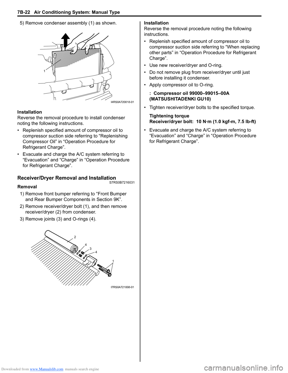
5) Remove condenser assembly (1) as shown.
Installation
Reverse the removal procedure to install condenser
noting the following instructions.
• Replenish specified amount of compressor oil to compressor suction side referring to “Replenishing
Compressor Oil” in “Operation Procedure for
Refrigerant Charge”.
• Evacuate and charge the A/C system referring to “Evacuation” and “Charge” in “Operation Procedure
for Refrigerant Charge”.
Receiver/Dryer Removal and InstallationS7RS0B7216031
Removal
1) Remove front bumper referring to “Front Bumper and Rear Bumper Components in Section 9K”.
2) Remove receiver/dryer bolt (1), and then remove receiver/dryer (2) from condenser.
3) Remove joints (3) and O-rings (4). Installation
Reverse the removal procedure noting the following
instructions.
• Replenish specified amount of compressor oil to
compressor suction side referring to “When replacing
other parts” in “Operation Procedure for Refrigerant
Charge”.
• Use new receiver/dryer and O-ring.
• Do not remove plug from receiver/dryer until just before installin g it condenser.
• Apply compressor oil to O-ring.
: Compressor oil 99000–99015–00A
(MATSUSHITADENKI GU10)
• Tighten receiver/dryer bolts to the specified torque. Tightening torque
Receiver/dryer bolt: 10 N· m (1.0 kgf-m, 7.5 lb-ft)
• Evacuate and charge the A/C system referring to “Evacuation” and “Charge” in “Operation Procedure
for Refrigerant Charge”.
1
I4RS0A720018-01
1
4
4
3
2
I7RS0A721008-01
Page 1287 of 1496

Downloaded from www.Manualslib.com manuals search engine Lighting Systems: 9B-5
Interior Light Symptom DiagnosisS7RS0B9204008
NOTE
• Use of SUZUKI scan tool makes it easy to check whether a faulty condition is on the input side or
output side of BCM. For checking procedure, re fer to “Diagnosis Using Output Test Function of
SUZUKI Scan Tool” under “Scan Tool Data in Section 10B”.
• Check each part in the order from the top of the following list.
Repair Instructions
Headlight Housing Removal and InstallationS7RS0B9206001
Removal 1) Disconnect negative (–) cable at battery.
2) Remove front bumper. Refer to “Front Bumper and Rear Bumper Componen ts in Section 9K”.
3) Remove headlight mounting bolts.
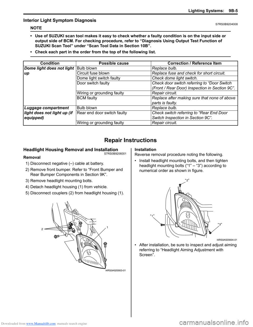
4) Detach headlight housing (1) from vehicle.
5) Disconnect couplers (2) from headlight housing (1). Installation
Reverse removal procedure noting the following.
• Install headlight mounting bolts, and then tighten
headlight mounting bolts (“1” – “3”) according to
numerical order as shown in figure.
• After installation, be sure to inspect and adjust aiming referring to “Headlight Aiming Adjustment with
Screen”.
Condition Possible cause Correction / Reference Item
Dome light does not light
up Bulb blown
Replace bulb.
Circuit fuse blown Replace fuse and check for short circuit.
Dome light switch faulty Check dome light switch.
Door switch faulty Check door switch referring to “Door Switch
(Front / Rear Door) Inspection in Section 9C”.
Wiring or grounding faulty Repair circuit.
BCM faulty Replace after making sure that none of above
parts is faulty.
Luggage compartment
light does not light up (if
equipped) Bulb blown
Replace bulb.
Rear end door switch faulty Check switch referring to “Rear End Door
Switch Inspection in Section 9C”.
Wiring or grounding faulty Repair circuit.
2 1
I4RS0A920003-01
2
1 3
I4RS0A920004-01
Page:
< prev 1-8 9-16 17-24