Page 857 of 1496

Downloaded from www.Manualslib.com manuals search engine Clutch: 5C-5
Clutch Pedal Position (CPP) Switch Inspection
and Adjustment
S7RS0B5306005
Inspection
Check for resistance between terminals under each
condition below. If check result is not satisfactory,
replace.
CPP switch resistance
When switch shaft is pushed (1): Continuity
When switch shaft is free (2): No continuityAdjustment
With clutch pedal depressed,
adjust switch (1) position
so that clearance between end of thread and clutch
pedal arm is within specification, and then tighten lock
nut to specified torque.
Clearance between end of thread and clutch pedal
arm
“a”: 3.5 – 4.0 mm (0.14 – 0.16 in.)
Tightening torque
CPP switch lock nut (a): 7.5 N·m (0.75 kgf-m, 5.5 lb-
ft)
Clutch Fluid Pipe and Hose ComponentsS7RS0B5306006
I5JB0A530006-01
(a)
1
“a”
I6RS0C530002-01
6
1
5
2 5
4(a)
3
I6RS0C530003-01
1. Master cylinder
: Apply grease 99000-25100 to push rod end. 5. Clamp
2. Pipe 6. Clutch reservoir hose
3. Operating cylinder : Apply grease 99000-25100 to rod tip. : 23 N
⋅m (2.3 kgf-m, 17.0 lb-ft)
4. Operating cylinder bolt
Page 858 of 1496
Downloaded from www.Manualslib.com manuals search engine 5C-6 Clutch:
Clutch Fluid Pipe Removal and InstallationS7RS0B5306007
Removal
CAUTION!
Do not allow fluid to get on painted surface. It
may cause painted surface damage.
1) Remove dust and dirt from each joint of pipe to be disconnected and clean around brake master
cylinder reservoir cap.
2) Take out fluid with syringe or such from brake master cylinder reservoir.
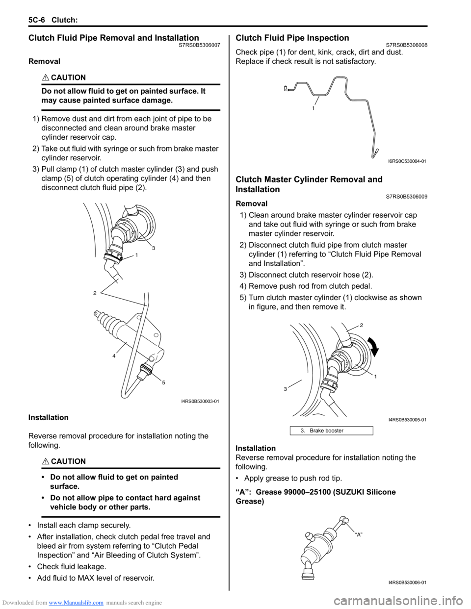
3) Pull clamp (1) of clutch master cylinder (3) and push clamp (5) of clutch operating cylinder (4) and then
disconnect clutch fluid pipe (2).
Installation
Reverse removal procedure for installation noting the
following.
CAUTION!
• Do not allow fluid to get on painted surface.
• Do not allow pipe to contact hard against vehicle body or other parts.
• Install each clamp securely.
• After installation, check clutch pedal free travel and bleed air from system referring to “Clutch Pedal
Inspection” and “Air Blee ding of Clutch System”.
• Check fluid leakage.
• Add fluid to MAX level of reservoir.
Clutch Fluid Pipe InspectionS7RS0B5306008
Check pipe (1) for dent, kink, crack, dirt and dust.
Replace if check result is not satisfactory.
Clutch Master Cylinder Removal and
Installation
S7RS0B5306009
Removal 1) Clean around brake master cylinder reservoir cap and take out fluid with syringe or such from brake
master cylinder reservoir.
2) Disconnect clutch fluid pipe from clutch master cylinder (1) referring to “C lutch Fluid Pipe Removal
and Installation”.
3) Disconnect clutch reservoir hose (2).
4) Remove push rod from clutch pedal.
5) Turn clutch master cylinder (1) clockwise as shown in figure, and then remove it.
Installation
Reverse removal procedure for installation noting the
following.
• Apply grease to push rod tip.
“A”: Grease 99000–25100 (SUZUKI Silicone
Grease)
31
2
5
4
I4RS0B530003-01
3. Brake booster
1
I6RS0C530004-01
1
2
3
I4RS0B530005-01
“A”
I4RS0B530006-01
Page 859 of 1496
Downloaded from www.Manualslib.com manuals search engine Clutch: 5C-7
Clutch Operating Cylinder Removal and
Installation
S7RS0B5306010
Removal1) Clean around brake master cylinder reservoir cap and take out fluid with syringe or such from brake
master cylinder reservoir.
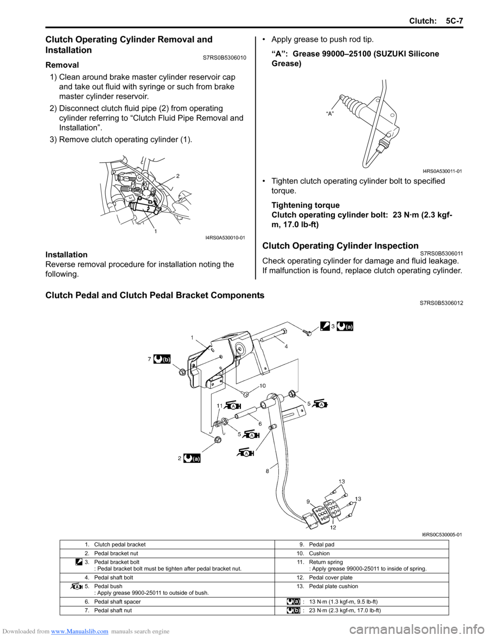
2) Disconnect clutch fluid pipe (2) from operating cylinder referring to “Clutch Fluid Pipe Removal and
Installation”.
3) Remove clutch operating cylinder (1).
Installation
Reverse removal procedure for installation noting the
following. • Apply grease to push rod tip.
“A”: Grease 99000–25100 (SUZUKI Silicone
Grease)
• Tighten clutch operating cylinder bolt to specified torque.
Tightening torque
Clutch operating cylinder bolt: 23 N·m (2.3 kgf-
m, 17.0 lb-ft)
Clutch Operating Cylinder InspectionS7RS0B5306011
Check operating cylinder for damage and fluid leakage.
If malfunction is found, repl ace clutch operating cylinder.
Clutch Pedal and Clutch Pedal Bracket ComponentsS7RS0B5306012
2
1I4RS0A530010-01
“A”
I4RS0A530011-01
I6RS0C530005-01
1. Clutch pedal bracket 9. Pedal pad
2. Pedal bracket nut 10. Cushion
3. Pedal bracket bolt : Pedal bracket bolt must be tighten after pedal bracket nut. 11. Return spring
: Apply grease 99000-25011 to inside of spring.
4. Pedal shaft bolt 12. Pedal cover plate
5. Pedal bush : Apply grease 9900-25011 to outside of bush. 13. Pedal plate cushion
6. Pedal shaft spacer : 13 N⋅m (1.3 kgf-m, 9.5 lb-ft)
7. Pedal shaft nut : 23 N⋅m (2.3 kgf-m, 17.0 lb-ft)
Page 860 of 1496
Downloaded from www.Manualslib.com manuals search engine 5C-8 Clutch:
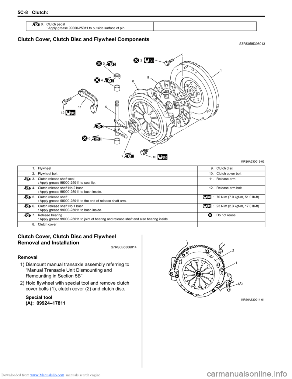
Clutch Cover, Clutch Disc and Flywheel ComponentsS7RS0B5306013
Clutch Cover, Clutch Disc and Flywheel
Removal and Installation
S7RS0B5306014
Removal1) Dismount manual transaxle assembly referring to “Manual Transaxle Unit Dismounting and
Remounting in Section 5B”.
2) Hold flywheel with specia l tool and remove clutch
cover bolts (1), clutch cover (2) and clutch disc.
Special tool
(A): 09924–17811
8. Clutch pedal : Apply grease 99000-25011 to outside surface of pin.
(a)
(b)
(b)
A
A
A
12
115
6
A3
A4
710
2
98
1
I4RS0A530013-02
1. Flywheel 9. Clutch disc
2. Flywheel bolt 10. Clutch cover bolt
3. Clutch release shaft seal : Apply grease 99000-25011 to seal lip. 11. Release arm
4. Clutch release shaft No.2 bush : Apply grease 99000-25011 to bush inside. 12. Release arm bolt
5. Clutch release shaft : Apply grease 99000-25011 to the end of release shaft arm. :70 N
⋅m (7.0 kgf-m, 51.0 lb-ft)
6. Clutch release shaft No.1 bush : Apply grease 99000-25011 to bush inside. :23 N
⋅m (2.3 kgf-m, 17.0 lb-ft)
7. Release bearing : Apply grease 99000-25011 to joint of bearing and release shaft and also bearing inside. Do not reuse.
8. Clutch cover
I4RS0A530014-01
Page 865 of 1496
Downloaded from www.Manualslib.com manuals search engine Clutch: 5C-13
Clutch Release System InspectionS7RS0B5306017
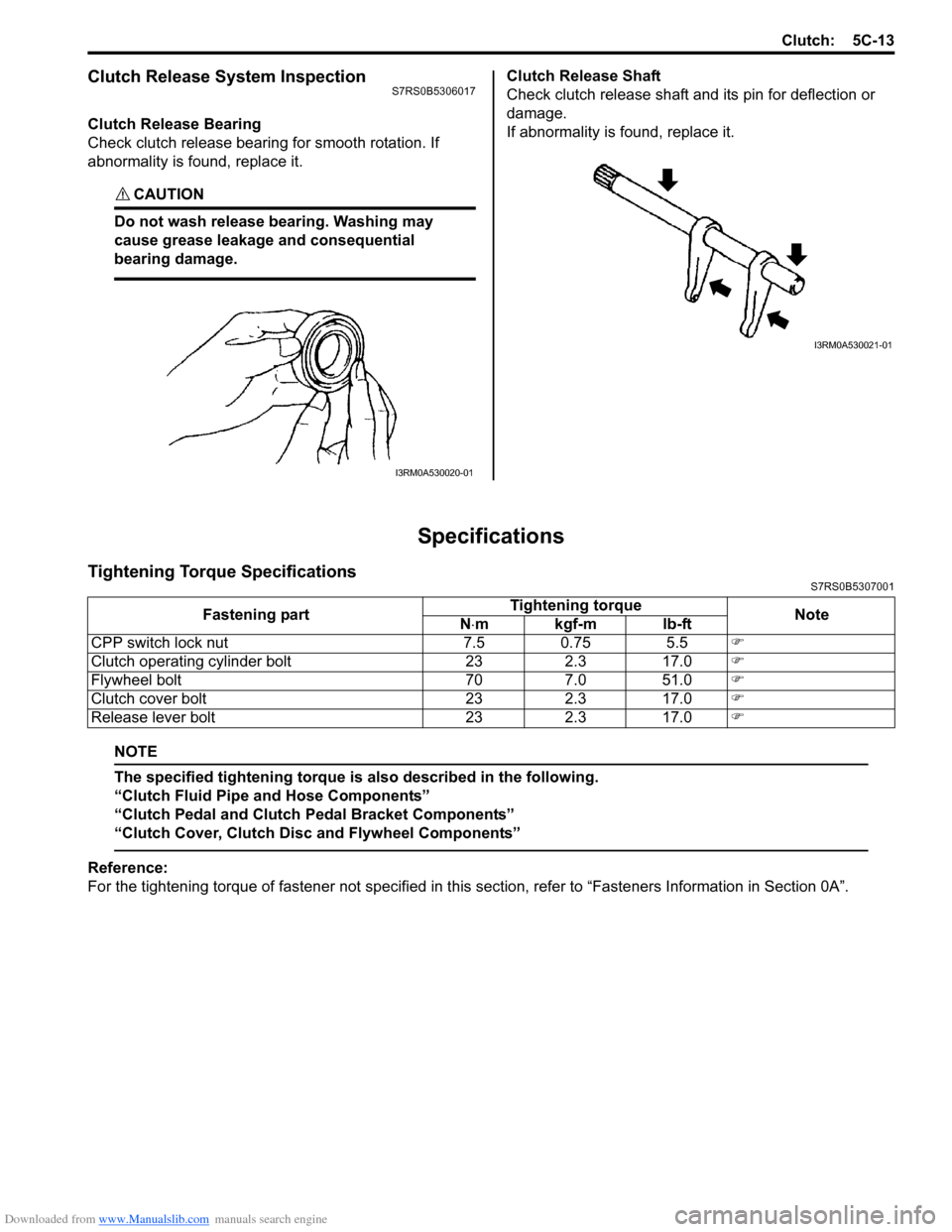
Clutch Release Bearing
Check clutch release bearing for smooth rotation. If
abnormality is found, replace it.
CAUTION!
Do not wash release bearing. Washing may
cause grease leakage and consequential
bearing damage.
Clutch Release Shaft
Check clutch release shaft and its pin for deflection or
damage.
If abnormality is found, replace it.
Specifications
Tightening Torque SpecificationsS7RS0B5307001
NOTE
The specified tightening torque is also described in the following.
“Clutch Fluid Pipe and Hose Components”
“Clutch Pedal and Clutch Pedal Bracket Components”
“Clutch Cover, Clutch Disc and Flywheel Components”
Reference:
For the tightening torque of fastener not specified in this section, refer to “Fasteners Information in Section 0A”.
I3RM0A530020-01
I3RM0A530021-01
Fastening part Tightening torque
Note
N ⋅mkgf-mlb-ft
CPP switch lock nut 7.5 0.75 5.5 �)
Clutch operating cylinder bolt 23 2.3 17.0 �)
Flywheel bolt 70 7.0 51.0 �)
Clutch cover bolt 23 2.3 17.0 �)
Release lever bolt 23 2.3 17.0 �)
Page 866 of 1496
Downloaded from www.Manualslib.com manuals search engine 5C-14 Clutch:
Special Tools and Equipment
Recommended Service MaterialS7RS0B5308001
NOTE
Required service material is also described in the following.
“Clutch Fluid Pipe and Hose Components”
“Clutch Pedal and Clutch Pedal Bracket Components”
“Clutch Cover, Clutch Disc and Flywheel Components”
Special ToolS7RS0B5308002
Material SUZUKI recommended product or Specification Note
Grease SUZUKI Super Grease A P/No.: 99000–25011�) / �) / �) / �)
SUZUKI Silicone Grease P/No.: 99000–25100�) / �)
SUZUKI Super Grease I P/No.: 99000–25210�) / �)
09921–26020 09922–46010
Bearing remover Clutch bush remover
�)�) / �)
09923–36320 09923–46020
Clutch center guide (15 mm) Joint pipe
�)�)
09923–46030 09924–17811
Joint pipe Flywheel holder
�)�) / �) / �) / �)
09925–98210 09925–98221
Input shaft bearing inst aller Bearing installer
�)�)
09930–30104 09943–88211
Sliding shaft Pinion bearing installer
�) / �)�)
Page 1187 of 1496
Downloaded from www.Manualslib.com manuals search engine Wiring Systems: 9A-16
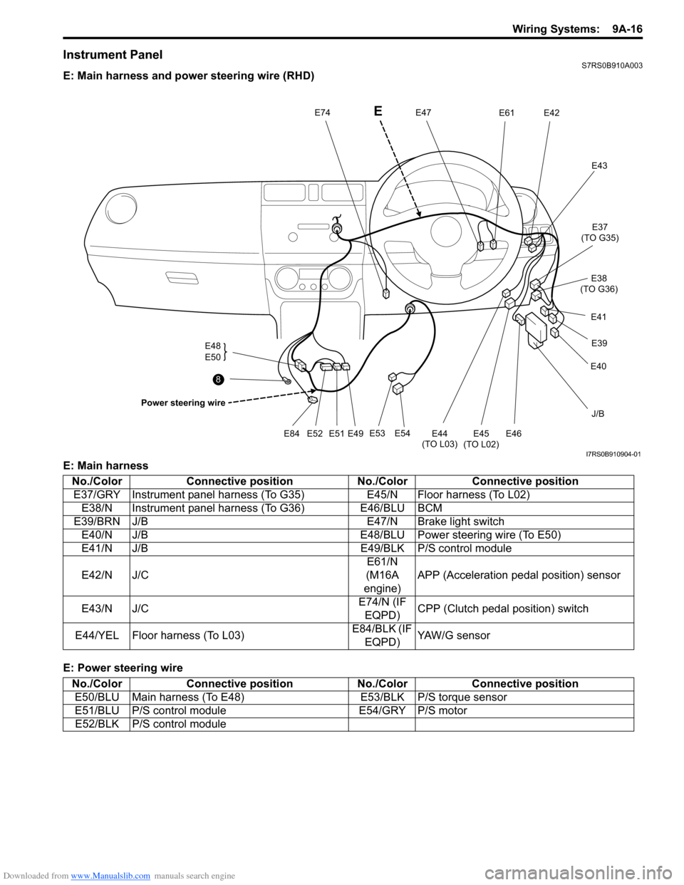
Instrument PanelS7RS0B910A003
E: Main harness and power steering wire (RHD)
E: Main harness
E: Power steering wire
J/B
E54
E53
E49
E51E52E84
E48
E50
Power steering wire
E47E74E42E61
E43
E45
(TO L02)
E44
(TO L03)E46
E40 E39
E41 E37
(TO G35)
E38
(TO G36)
8
E
I7RS0B910904-01
No./Color Connective position No./ColorConnective position
E37/GRY Instrument panel harness (To G35) E45/N Floor harness (To L02)
E38/N Instrument panel harness (To G36) E46/BLU BCM
E39/BRN J/B E47/N Brake light switch
E40/N J/B E48/BLU Power steering wire (To E50)
E41/N J/B E49/BLK P/S control module
E42/N J/C E61/N
(M16A
engine) APP (Acceleration pedal position) sensor
E43/N J/C E74/N (IF
EQPD) CPP (Clutch pedal position) switch
E44/YEL Floor harness (To L03) E84/BLK (IF
EQPD) YAW/G sensor
No./Color Connective position No./ColorConnective position
E50/BLU Main harness (To E48) E53/BLK P/S torque sensor
E51/BLU P/S control module E54/GRY P/S motor
E52/BLK P/S control module
Page:
< prev 1-8 9-16 17-24