2007 SUZUKI SWIFT Tail light
[x] Cancel search: Tail lightPage 1216 of 1496

Downloaded from www.Manualslib.com manuals search engine 9A-45 Wiring Systems:
System Circuit Diagram
System Circuit DiagramS7RS0B910E001
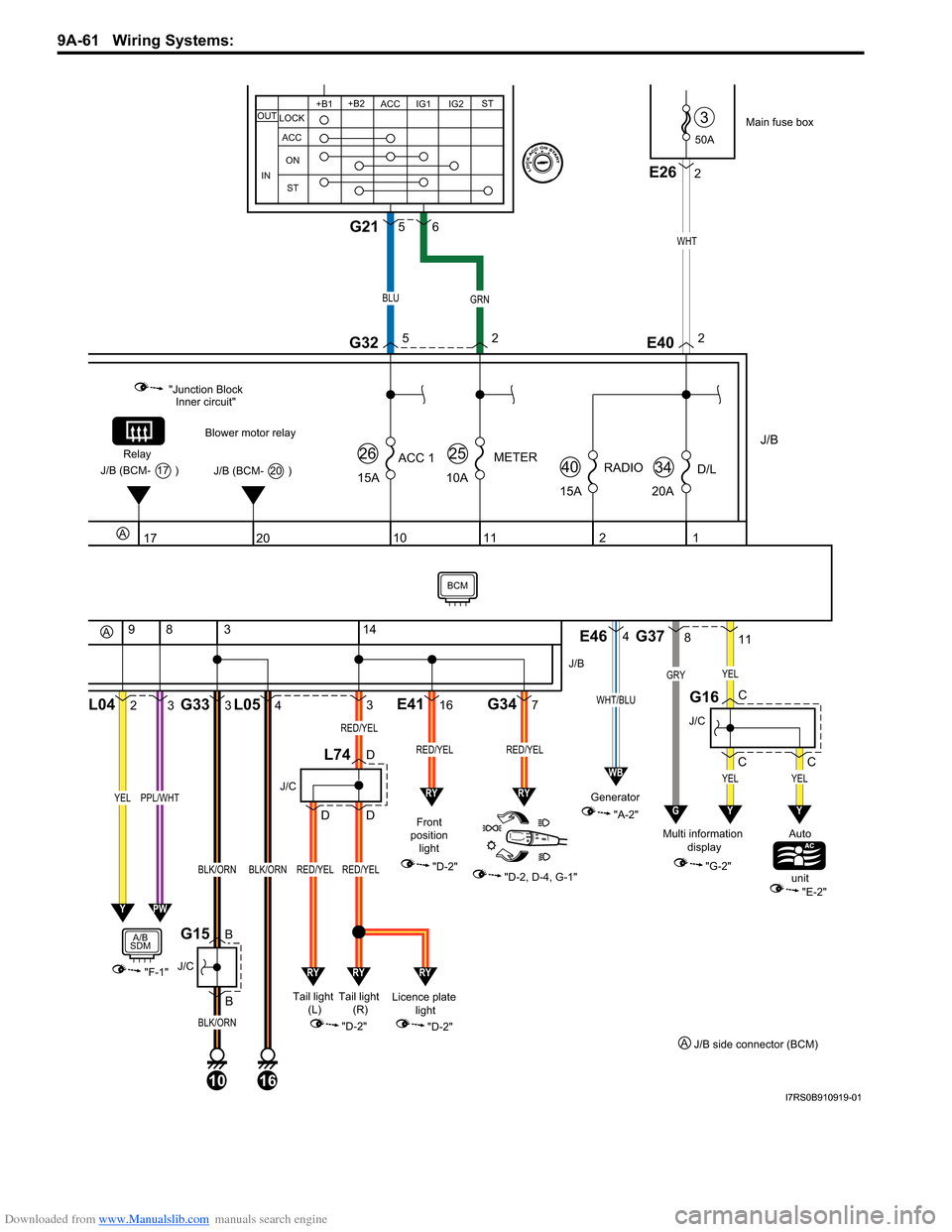
Refer to “A-1 Cranking System Circuit Diagram”.
Refer to “A-2 Charging System Circuit Diagram”.
Refer to “A-3 Ignition System Circuit Diagram”.
Refer to “A-4 Cooling System Circuit Diagram”.
Refer to “A-5 Engine and A/C Control System Circuit Diagram”.
Refer to “A-6 A/T Control System Circuit Diagram”.
Refer to “A-7 Immobilizer System Circuit Diagram”.
Refer to “A-8 Body Control System Circuit Diagram”.
Refer to “B-1 Windshield Wiper and Washer Circuit Diagram”.
Refer to “B-2 Rear Wiper and Washer Circuit Diagram”.
Refer to “B-3 Rear Defogger Circuit Diagram”.
Refer to “B-4 Power Window Circuit Diagram”.
Refer to “B-5 Power Door Lock Circuit Diagram”.
Refer to “B-6 Power Mi rror Circuit Diagram”.
Refer to “B-7 Horn Circuit Diagram”.
Refer to “B-8 Seat Heater Circuit Diagram”.
Refer to “B-9 Keyless Star t System Circuit Diagram”.
Refer to “C-1 Combination Me ter Circuit Diagram (Meter)”.
Refer to “C-2 Combination Mete r Circuit Diagram (Indicator)”.
Refer to “C-3 Combination Meter Circuit Diagram (Warning Light)”.
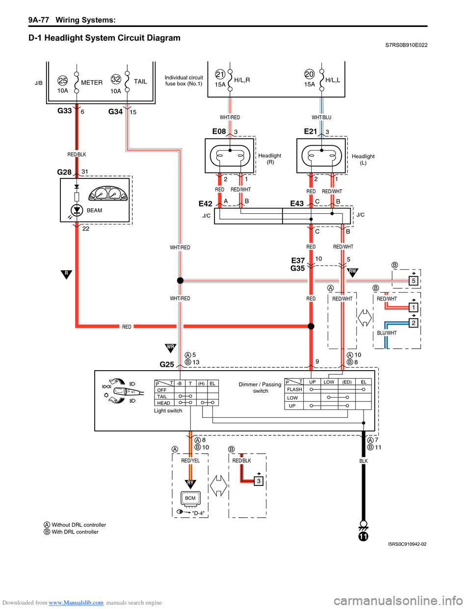
Refer to “D-1 Headlight System Circuit Diagram”.
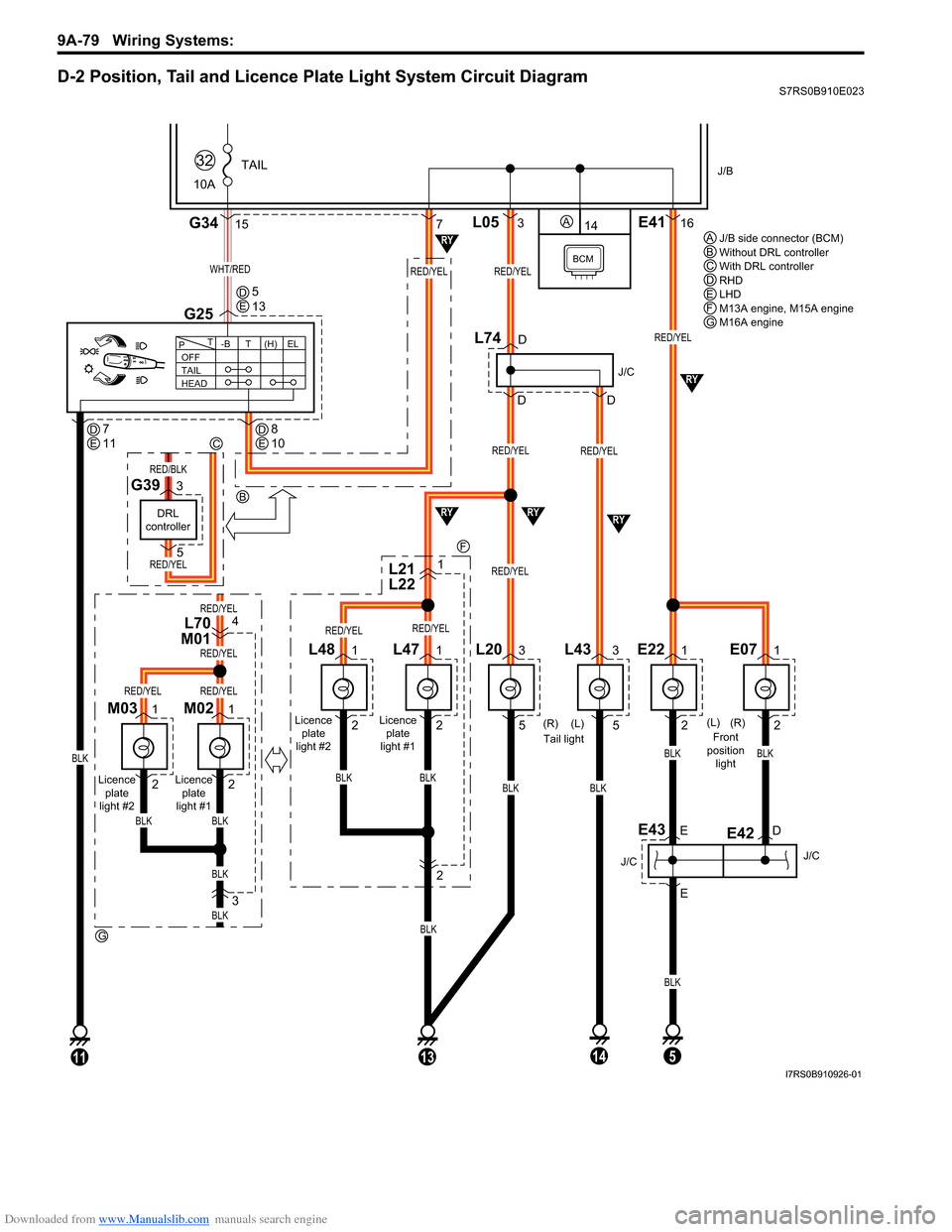
Refer to “D-2 Position, Tail and Licence Plate Light System Circuit Diagram”.
Refer to “D-3 Front Fog Light System Circuit Diagram”.
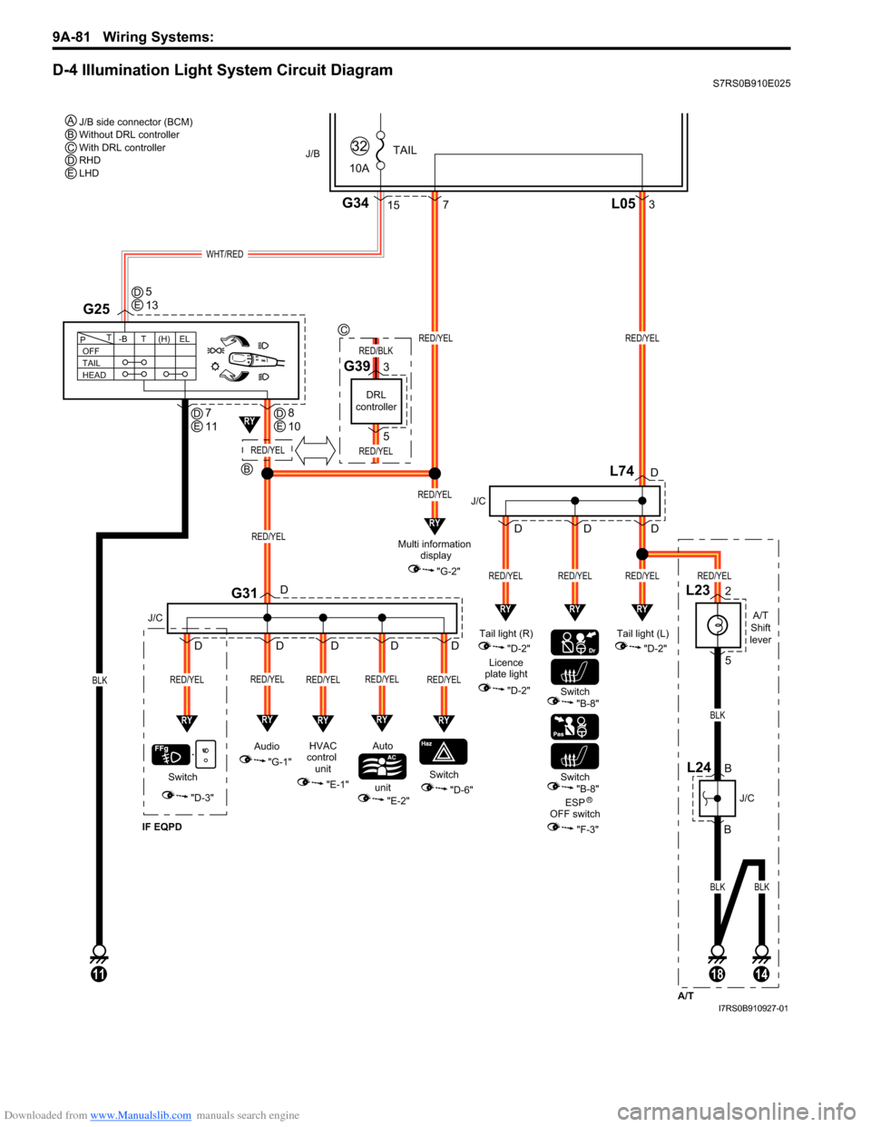
Refer to “D-4 Illumination Light System Circuit Diagram”.
Refer to “D-5 Interior Li ght System Circuit Diagram”.
Refer to “D-6 Turn Signal and Hazard Warning Light System Circuit Diagram”.
Refer to “D-7 Brake Light System Circuit Diagram”.
Refer to “D-8 Back-Up Light System Circuit Diagram”.
Refer to “D-9 Headlight Beam Leveling System Circuit Diagram”.
Refer to “D-10 Rear Fog Light Circuit Diagram”.
Refer to “E-1 Heater System Circuit Diagram”.
Refer to “E-2 Auto A/C System Circuit Diagram”.
Refer to “F-1 Air-Bag System Circuit Diagram”.
Refer to “F-2 Anti-Lock Brake System Circuit Diagram”.
Refer to “F-3 Electronic Stabilit y Program System Circuit Diagram”.
Refer to “F-4 Power Steeri ng System Circuit Diagram”.
Refer to “G-1 Audio Sy stem Circuit Diagram”.
Refer to “G-2 Multi Information Display / Accessory Socket System Circuit Diagram”.
Page 1232 of 1496
Downloaded from www.Manualslib.com manuals search engine 9A-61 Wiring Systems:
50A
3
J/B
15ARADIO
40
2
15A
ACC 1
26
10
1
20AD/L
34
11
10A
METER
25
Main fuse box
WHT
E402
20
Blower motor relay
"Junction Block Inner circuit"
Relay
J/B (BCM- 20 )J/B (BCM- 17 )
17
2L04
9
3
83
B BG33
3
4L05
10
J/C
G15
BLK/ORN
BLK/ORN
16
BLK/ORN
"F-1"
YELPPL/WHT
A/B
SDM
14
316E417G34
Front
position light
"D-2"
"D-2, D-4, G-1"
J/B
RED/YELRED/YEL
J/C
L74D
DD
Licence plate light
"D-2"
YPW
"A-2"
Generator
E464
WHT/BLU
WB
RYRY
RYRYRY
Tail light
(R)
Tail light
(L)
"D-2"
RED/YEL
RED/YEL
RED/YEL
811
C CG37
J/C
G16
YEL
GRYYEL
GY
C
YEL
Y
"G-2"
Multi information
display Auto
unit
"E-2"
A
A
J/C
2E26
+B1
LOCK
ACC
ON
ST ACC IG1 IG2
STOUT
IN
+B2
BLUGRN
G3252
56G21
J/B side connector (BCM)
A
BCM
I7RS0B910919-01
Page 1248 of 1496
Downloaded from www.Manualslib.com manuals search engine 9A-77 Wiring Systems:
D-1 Headlight System Circuit DiagramS7RS0B910E022
1
Headlight (R) Headlight
(L)
WHT/BLU
RED
Dimmer / Passing switch
Light switch
2
2
BA BC
B
C
33
15
1
22G28
E08
G34
E21
G336
31
RED/BLK
WHT/RED
WHT/RED
10A
25METER
WHT/RED
9
BLK
11
G25
15A
21
15A
20H/L,R H/L,L
RED/WHTRED
10
RED
RED
J/B
10ATAIL
32
RED/WHTRED/WHT
BLU/WHT
5
RED/WHT
E37
G35
E42
J/C
REDRED/WHT
BEAM
FLASH UPLOW
T
P(ED)EL
UP
LOW
OFF
TAIL
HEAD -BT
T
P(H) EL
RY
RED/YEL
"D-4"
BCM
R
WR
RW
E43
J/C
Individual circuit
fuse box (No.1)
Without DRL controller
AWith DRL controller
B
A
5
1
2
3
AB
B
RED/BLK
B
AB5
13AB10
8
AB7
11AB8
10
I5RS0C910942-02
Page 1250 of 1496
Downloaded from www.Manualslib.com manuals search engine 9A-79 Wiring Systems:
D-2 Position, Tail and Licence Plate Light System Circuit DiagramS7RS0B910E023
G
12M0212M03
BLKBLK
BLK
BLK
RED/YEL
RED/YEL
RED/YELRED/YEL
4
3L70
M01
3
5L431
2L47
(L) (R)
(R) (L)
BLK
RED/YELRED/YEL
RED/YEL
7
J/C
L74
E42
15G34
BLK
G25
10A TAIL
32
1
2E071
D
DD
2
ED EE22
BLK
BLK
RED/YEL
J/B
L053E4116
BLK
BLK
E43
J/C
Licence plate
light #1
3
5L20
BLK
BCM
14
11513
WHT/RED
OFF
TAIL
HEAD -BT
T
P(H) EL
A
Front
position light
RED/YEL
Tail light
RY
14
RY
RY
RY
J/C
J/B side connector (BCM)
Without DRL controller
With DRL controller
RHD
LHD
M13A engine, M15A engine
M16A engine
A
BCDEFG
L21
L22
RY
BLK
RED/YEL
RED/YEL
1
2L48
Licence plate
light #2
Licence plate
light #1
Licence
plate
light #2
RED/YEL
RED/BLK
RED/YEL
BLK
3
5G39
DRL
controller
1
2
DE5
13
DE7
11DE
B
F
C8
10
I7RS0B910926-01
Page 1252 of 1496
Downloaded from www.Manualslib.com manuals search engine 9A-81 Wiring Systems:
D-4 Illumination Light System Circuit DiagramS7RS0B910E025
WHT/RED
A/T
Shift
lever
L23
L742
5
BLK
BLKBLK
10A
TAIL
32J/B
15G34
BLK
G25
111814
A/T
B
B
J/C
L24
RED/YEL
RED/YEL
L053
"D-3"
IF EQPD
RY
Switch
J/C J/C
G31
RED/YEL
RY
RED/YEL
Switch
RY
RED/YEL
HVAC
control unit Auto
unit
"E-1"
"E-2""D-6"
OFF
TAIL
HEAD -BT
T
P(H) ELRED/YEL
7
RY
RED/YEL
Audio
"G-1"
D
D
D
D
D
D
D
RY
RED/YEL
D
D
RY
RY
RED/YEL
Multi information
display
"G-2"RED/YEL
RED/YEL
RED/YEL
RY
Tail light (L) "D-2"
RED/YEL
RY
Tail light (R) "D-2"
Licence
plate light
"D-2"
J/B side connector (BCM)
Without DRL controller
With DRL controller
RHD
LHD
A
R
BCDE
Switch
"B-8"
Switch"B-8"
ESP
OFF switch
"F-3"
DE5
13
DE7
11DE
B
C
8
10
DRL
controller
G393
5
RED/YEL
RED/BLK
RED/YEL
D
RY
I7RS0B910927-01
Page 1285 of 1496
Downloaded from www.Manualslib.com manuals search engine Lighting Systems: 9B-3
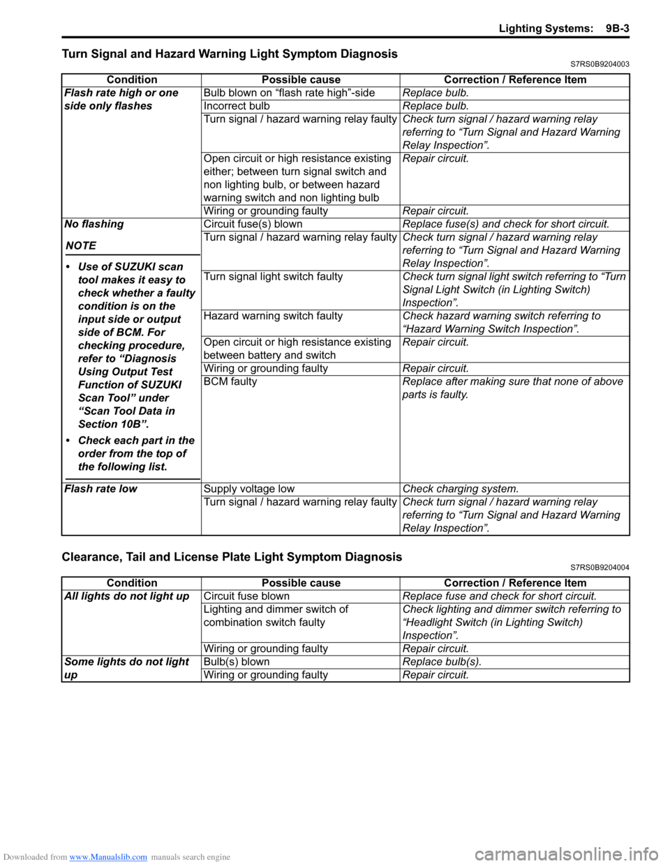
Turn Signal and Hazard Warning Light Symptom DiagnosisS7RS0B9204003
Clearance, Tail and License Plate Light Symptom DiagnosisS7RS0B9204004
ConditionPossible cause Correction / Reference Item
Flash rate high or one
side only flashes Bulb blown on “flash rate high”-side
Replace bulb.
Incorrect bulb Replace bulb.
Turn signal / hazard warning relay faulty Check turn signal / hazard warning relay
referring to “Turn Signal and Hazard Warning
Relay Inspection”.
Open circuit or high resistance existing
either; between turn signal switch and
non lighting bulb, or between hazard
warning switch and non lighting bulb Repair circuit.
Wiring or grounding faulty Repair circuit.
No flashing
NOTE
• Use of SUZUKI scan tool makes it easy to
check whether a faulty
condition is on the
input side or output
side of BCM. For
checking procedure,
refer to “Diagnosis
Using Output Test
Function of SUZUKI
Scan Tool” under
“Scan Tool Data in
Section 10B”.
• Check each part in the order from the top of
the following list.
Circuit fuse(s) blown Replace fuse(s) and check for short circuit.
Turn signal / hazard warning relay faulty Check turn signal / hazard warning relay
referring to “Turn Signal and Hazard Warning
Relay Inspection”.
Turn signal light switch faulty Check turn signal light switch referring to “Turn
Signal Light Switch (in Lighting Switch)
Inspection”.
Hazard warning switch faulty Check hazard warning switch referring to
“Hazard Warning Switch Inspection”.
Open circuit or high resistance existing
between battery and switch Repair circuit.
Wiring or grounding faulty Repair circuit.
BCM faulty Replace after making sure that none of above
parts is faulty.
Flash rate low Supply voltage low Check charging system.
Turn signal / hazard warning relay faulty Check turn signal / hazard warning relay
referring to “Turn Signal and Hazard Warning
Relay Inspection”.
ConditionPossible cause Correction / Reference Item
All lights do not light up Circuit fuse blown Replace fuse and check for short circuit.
Lighting and dimmer switch of
combination switch faulty Check lighting and dimmer switch referring to
“Headlight Switch (in Lighting Switch)
Inspection”.
Wiring or grounding faulty Repair circuit.
Some lights do not light
up Bulb(s) blown
Replace bulb(s).
Wiring or grounding faulty Repair circuit.
Page 1367 of 1496
Downloaded from www.Manualslib.com manuals search engine Interior Trim: 9H-1
Body, Cab and Accessories
Interior Trim
Repair Instructions
Floor Carpet Removal and InstallationS7RS0B9806001
WARNING!
Refer to “Air Bag Warning in Section 00”
before starting service work.
Removal1) Remove front seats and rear seats referring to “Front Seat Removal and Installa tion in Section 9G” and
“Rear Seat Removal and Installation in Section 9G”.
2) Remove seat belt lower anchor bolt.
3) Remove dash side trims, fr ont side sill scuffs, center
pillar inner lower trims, qu arter inner front trims and
rear side sill scuffs.
4) Remove console box.
5) Remove floor carpet.
Installation
Reverse removal sequence to install floor carpet, noting
the following instruction.
• For tightening torque of rear seat mounting bolt, refer to “Rear Seat Components in Section 9G”.
• For tightening torque of front seat mounting bolt, refer to “Front Seat Components in Section 9G”.
Head Lining Removal and InstallationS7RS0B9806002
WARNING!
Refer to “Air Bag Warning in Section 00”
before starting service work.
Removal
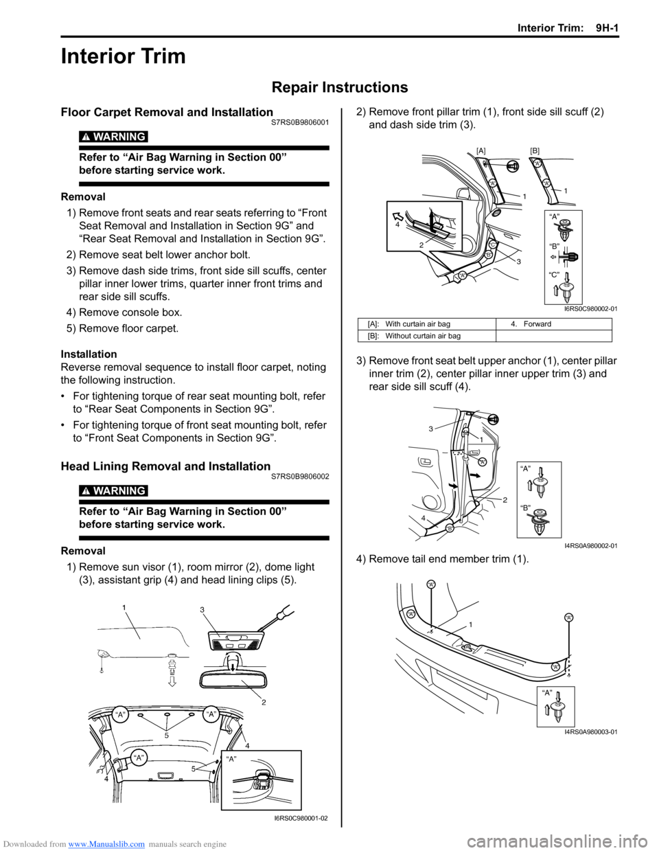
1) Remove sun visor (1), room mirror (2), dome light (3), assistant grip (4) and head lining clips (5). 2) Remove front pillar trim (1
), front side sill scuff (2)
and dash side trim (3).
3) Remove front seat belt u pper anchor (1), center pillar
inner trim (2), center pillar inner upper trim (3) and
rear side sill scuff (4).
4) Remove tail end member trim (1).
I6RS0C980001-02
[A]: With curtain air bag 4. Forward
[B]: Without curtain air bag
“A”“A”
“A”
2
4
1
3
“A”
“A”
1
[B]
[A]
“B”“B”
“C”“C”
I6RS0C980002-01
“A”
“B”
“A”
“B”
1
3
2
4
I4RS0A980002-01
“A”
“A”
“A”
“A”“A”1
I4RS0A980003-01
Page 1404 of 1496
Downloaded from www.Manualslib.com manuals search engine 10B-1 Body Electrical Control System:
Control Systems
Body Electrical Control System
Precautions
Precautions in Diagnosing TroubleS7RS0BA200001
• Diagnostic information stored in BCM memory can be cleared as well as checked by using SUZUKI scan tool.
Before using scan tool, read its Operator ’s (Instruction) Manual carefully to have good understanding as to what
functions are available and how to use it.
• Be sure to read “Precautions for Electrical Circuit Serv ice in Section 00” before inspection and observe what is
written there.
• Communication of ECM, TCM (if equipped), ABS/ESP ® control module, steering angle sensor (ESP ® model),
keyless start control module (if equipped), combinatio n meter and BCM is established by CAN (Controller Area
Network). For detail of CAN communication for BCM, refer to “CAN Communication System Description”.
Therefore, handle CAN communication line with care referr ing to “Precaution for CAN Communication System in
Section 00”.
General Description
BCM General DescriptionS7RS0BA201001
The Body electrical Control Module (BCM) is incorporated in junction block assembly. Do not attempt removal of BCM
from junction block assembly as it may cause contact failure.
The BCM incorporates relays and controllers which are used for the following systems and controls them.
• Power door lock
• Keyless entry (if equipped)
• Door lock function of keyle ss start system (if equipped)
• Rear wiper
• Combination meter
• Interior light
• Warning buzzer
• Rear end door window defogger and door mirror heater (if equipped)
• Rear end door opener
• Theft deterrent light
Also, the BCM has a function to cause the interior light and open door warning lamp in the combination meter to turn
off when any door is left open for longer than 15 minutes to reduce wasteful battery consumption.
In addition, it is possible to check operation of actuator whic h is controlled by BCM by using the output test function of
SUZUKI scan tool to operate actuator simulatively.