2007 SUZUKI SWIFT Output speed sensor
[x] Cancel search: Output speed sensorPage 228 of 1496
Downloaded from www.Manualslib.com manuals search engine 1A-178 Engine General Information and Diagnosis:
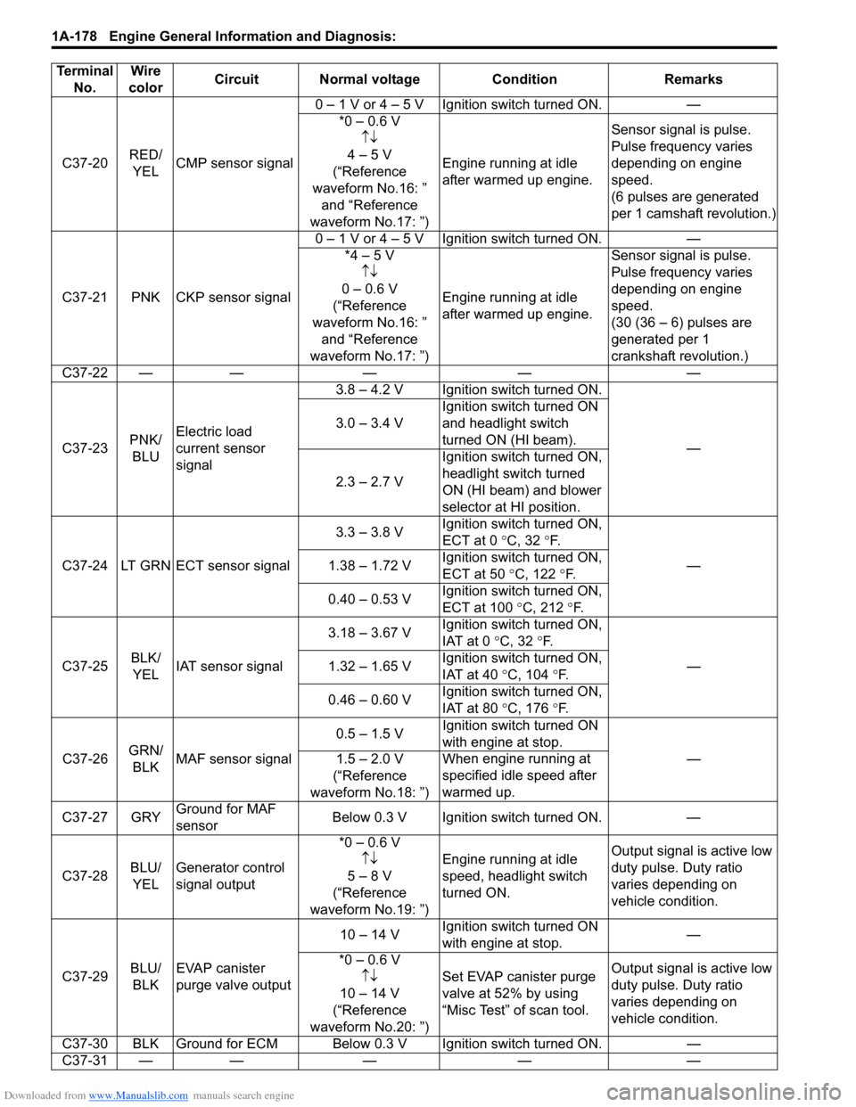
C37-20RED/
YEL CMP sensor signal 0 – 1 V or 4 – 5 V Ignition switch turned ON. —
*0 – 0.6 V↑↓
4 – 5 V
(“Reference
waveform No.16: ” and “Reference
waveform No.17: ”) Engine running at idle
after warmed up engine.
Sensor signal is pulse.
Pulse frequency varies
depending on engine
speed.
(6 pulses are generated
per 1 camshaft revolution.)
C37-21 PNK CKP sensor signal 0 – 1 V or 4 – 5 V Ignition switch turned ON. —
*4 – 5 V↑↓
0 – 0.6 V
(“Reference
waveform No.16: ” and “Reference
waveform No.17: ”) Engine running at idle
after warmed up engine. Sensor signal is pulse.
Pulse frequency varies
depending on engine
speed.
(30 (36 – 6) pulses are
generated per 1
crankshaft revolution.)
C37-22 — — — — —
C37-23 PNK/
BLU Electric load
current sensor
signal 3.8 – 4.2 V Ignition switch turned ON.
—
3.0 – 3.4 V
Ignition switch turned ON
and headlight switch
turned ON (HI beam).
2.3 – 2.7 V Ignition switch turned ON,
headlight switch turned
ON (HI beam) and blower
selector at HI position.
C37-24 LT GRN ECT sensor signal 3.3 – 3.8 V
Ignition switch turned ON,
ECT at 0
°C, 32 °F.
—
1.38 – 1.72 V Ignition switch turned ON,
ECT at 50
°C, 122 °F.
0.40 – 0.53 V Ignition switch turned ON,
ECT at 100
°C, 212 °F.
C37-25 BLK/
YEL IAT sensor signal 3.18 – 3.67 V
Ignition switch turned ON,
IAT at 0
°C, 32 °F.
—
1.32 – 1.65 V Ignition switch turned ON,
IAT at 40
°C, 104 °F.
0.46 – 0.60 V Ignition switch turned ON,
IAT at 80
°C, 176 °F.
C37-26 GRN/
BLK MAF sensor signal 0.5 – 1.5 V
Ignition switch turned ON
with engine at stop.
—
1.5 – 2.0 V
(“Reference
waveform No.18: ”) Wh
en engine running at
specified idle speed after
warmed up.
C37-27 GRY Ground for MAF
sensor Below 0.3 V Ignition switch turned ON.
—
C37-28 BLU/
YEL Generator control
signal output *0 – 0.6 V
↑↓
5 – 8 V
(“Reference
waveform No.19: ”) Engine running at idle
speed, headlight switch
turned ON.
Output signal is active low
duty pulse. Duty ratio
varies depending on
vehicle condition.
C37-29 BLU/
BLK EVAP canister
purge valve output 10 – 14 V
Ignition switch turned ON
with engine at stop. —
*0 – 0.6 V ↑↓
10 – 14 V
(“Reference
waveform No.20: ”) Set EVAP canister purge
valve at 52% by using
“Misc Test” of scan tool.
Output signal is active low
duty pulse. Duty ratio
varies depending on
vehicle condition.
C37-30 BLK Ground for ECM Below 0.3 V Ignition switch turned ON. —
C37-31 — —— — —
Terminal
No. Wire
color Circuit Normal voltage
ConditionRemarks
Page 230 of 1496
Downloaded from www.Manualslib.com manuals search engine 1A-180 Engine General Information and Diagnosis:
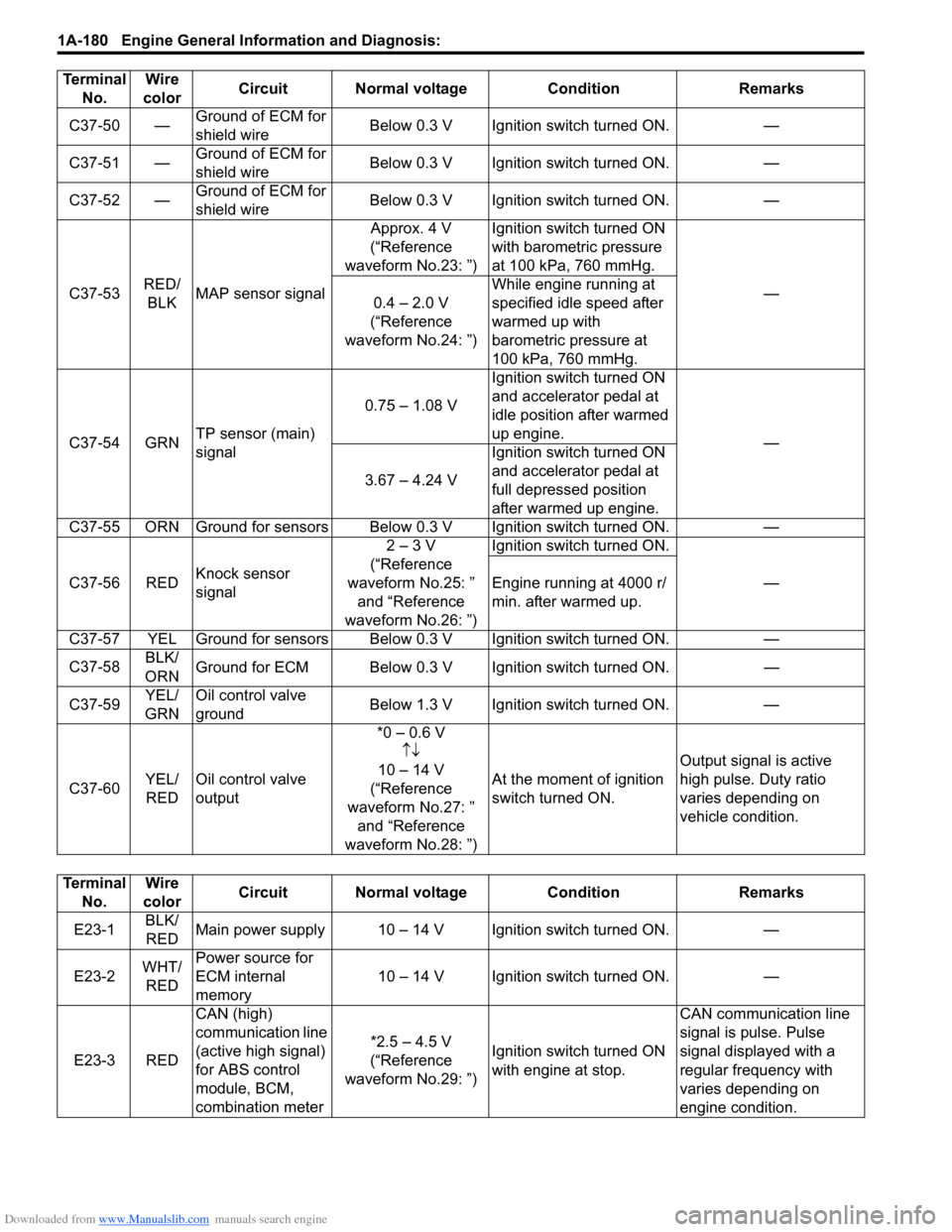
C37-50 —Ground of ECM for
shield wire Below 0.3 V Ignition switch turned ON. —
C37-51 — Ground of ECM for
shield wire Below 0.3 V Ignition switch turned ON. —
C37-52 — Ground of ECM for
shield wire Below 0.3 V Ignition switch turned ON. —
C37-53 RED/
BLK MAP sensor signal Approx. 4 V
(“Reference
waveform No.23: ”) Ignition switch turned ON
with barometric pressure
at 100 kPa, 760 mmHg.
—
0.4 – 2.0 V
(“Reference
waveform No.24: ”) While engine running at
specified idle speed after
warmed up with
barometric pressure at
100 kPa, 760 mmHg.
C37-54 GRN TP sensor (main)
signal 0.75 – 1.08 V
Ignition switch turned ON
and accelerator pedal at
idle position after warmed
up engine.
—
3.67 – 4.24 V Ignition switch turned ON
and accelerator pedal at
full depressed position
after warmed up engine.
C37-55 ORN Ground for sensors Below 0.3 V Ignition switch turned ON. —
C37-56 RED Knock sensor
signal 2 – 3 V
(“Reference
waveform No.25: ” and “Reference
waveform No.26: ”) Ignition switch turned ON.
—
Engine running at 4000 r/
min. after warmed up.
C37-57 YEL Ground for sensors Below 0.3 V Ignition switch turned ON. —
C37-58 BLK/
ORN Ground for ECM Below 0.3 V Ignition switch turned ON.
—
C37-59 YEL/
GRN Oil control valve
ground
Below 1.3 V Ignition switch turned ON.
—
C37-60 YEL/
RED Oil control valve
output *0 – 0.6 V
↑↓
10 – 14 V
(“Reference
waveform No.27: ” and “Reference
waveform No.28: ”) At the moment of ignition
switch turned ON.
Output signal is active
high pulse. Duty ratio
varies depending on
vehicle condition.
Terminal
No. Wire
color Circuit Normal voltage
ConditionRemarks
Terminal
No. Wire
color Circuit Normal voltage Condition Remarks
E23-1 BLK/
RED Main power supply 10 – 14 V Ignition switch turned ON. —
E23-2 WHT/
RED Power source for
ECM internal
memory
10 – 14 V Ignition switch turned ON. —
E23-3 RED CAN (high)
communication line
(active high signal)
for ABS control
module, BCM,
combination meter *2.5 – 4.5 V
(“Reference
waveform No.29: ”) Ignition switch turned ON
with engine at stop. CAN communication line
signal is pulse. Pulse
signal displayed with a
regular frequency with
varies depending on
engine condition.
Page 232 of 1496
Downloaded from www.Manualslib.com manuals search engine 1A-182 Engine General Information and Diagnosis:
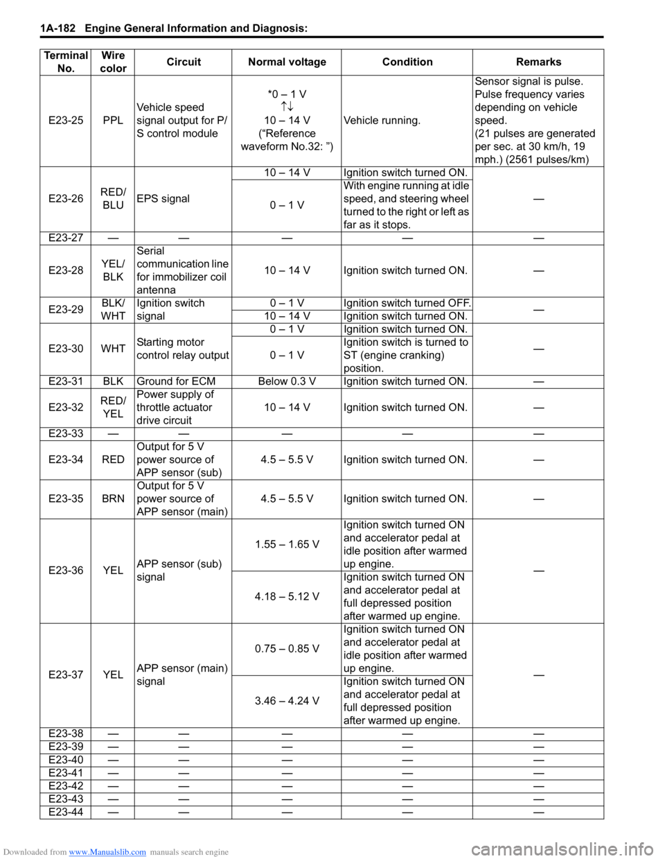
E23-25 PPLVehicle speed
signal output for P/
S control module *0 – 1 V
↑↓
10 – 14 V
(“Reference
waveform No.32: ”) Vehicle running. Sensor signal is pulse.
Pulse frequency varies
depending on vehicle
speed.
(21 pulses are generated
per sec. at 30 km/h, 19
mph.) (2561 pulses/km)
E23-26 RED/
BLU EPS signal 10 – 14 V Ignition switch turned ON.
—
0 – 1 V With engine running at idle
speed, and steering wheel
turned to the right or left as
far as it stops.
E23-27 — — — — —
E23-28 YEL/
BLK Serial
communication line
for immobilizer coil
antenna
10 – 14 V Ignition switch turned ON. —
E23-29 BLK/
WHT Ignition switch
signal 0 – 1 V Ignition switch turned OFF.
—
10 – 14 V Ignition switch turned ON.
E23-30 WHT Starting motor
control relay output 0 – 1 V Ignition switch turned ON.
—
0 – 1 V Ignition switch is turned to
ST (engine cranking)
position.
E23-31 BLK Ground for ECM Below 0.3 V Ignition switch turned ON. —
E23-32 RED/
YEL Power supply of
throttle actuator
drive circuit
10 – 14 V Ignition switch turned ON. —
E23-33 — — — — —
E23-34 RED Output for 5 V
power source of
APP sensor (sub) 4.5 – 5.5 V Ignition switch turned ON. —
E23-35 BRN Output for 5 V
power source of
APP sensor (main) 4.5 – 5.5 V Ignition switch turned ON. —
E23-36 YEL APP sensor (sub)
signal 1.55 – 1.65 V
Ignition switch turned ON
and accelerator pedal at
idle position after warmed
up engine.
—
4.18 – 5.12 V Ignition switch turned ON
and accelerator pedal at
full depressed position
after warmed up engine.
E23-37 YEL APP sensor (main)
signal 0.75 – 0.85 V
Ignition switch turned ON
and accelerator pedal at
idle position after warmed
up engine.
—
3.46 – 4.24 V Ignition switch turned ON
and accelerator pedal at
full depressed position
after warmed up engine.
E23-38 — — — — —
E23-39 — — — — —
E23-40 — — — — —
E23-41 — — — — —
E23-42 — — — — —
E23-43 — — — — —
E23-44 — — — — —
Terminal
No. Wire
color Circuit Normal voltage Condition Remarks
Page 234 of 1496
Downloaded from www.Manualslib.com manuals search engine 1A-184 Engine General Information and Diagnosis:
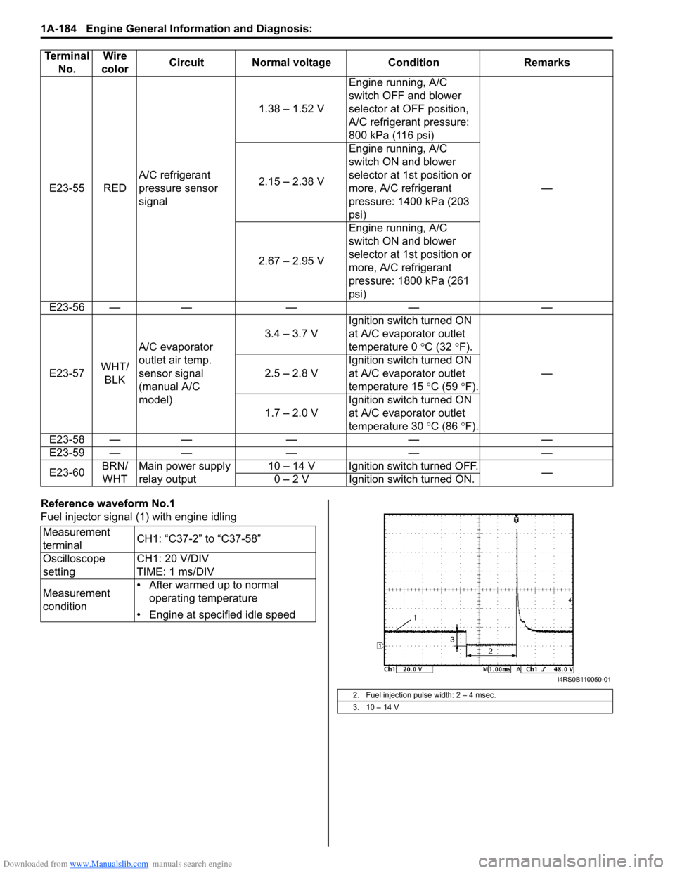
Reference waveform No.1
Fuel injector signal (1) with engine idling
E23-55 RED
A/C refrigerant
pressure sensor
signal 1.38 – 1.52 V
Engine running, A/C
switch OFF and blower
selector at OFF position,
A/C refrigerant pressure:
800 kPa (116 psi)
—
2.15 – 2.38 V Engine running, A/C
switch ON and blower
selector at 1st position or
more, A/C refrigerant
pressure: 1400 kPa (203
psi)
2.67 – 2.95 V Engine running, A/C
switch ON and blower
selector at 1st position or
more, A/C refrigerant
pressure: 1800 kPa (261
psi)
E23-56 — — — — —
E23-57 WHT/
BLK A/C evaporator
outlet air temp.
sensor signal
(manual A/C
model) 3.4 – 3.7 V
Ignition switch turned ON
at A/C evaporator outlet
temperature 0
°C (32 °F).
—
2.5 – 2.8 V Ignition switch turned ON
at A/C evaporator outlet
temperature 15
°C (59 °F).
1.7 – 2.0 V Ignition switch turned ON
at A/C evaporator outlet
temperature 30
°C (86 °F).
E23-58 — — — — —
E23-59 — — — — —
E23-60 BRN/
WHT Main power supply
relay output 10 – 14 V Ignition switch turned OFF.
—
0 – 2 V Ignition switch turned ON.
Terminal
No. Wire
color Circuit Normal voltage Condition Remarks
Measurement
terminal CH1: “C37-2” to “C37-58”
Oscilloscope
setting CH1: 20 V/DIV
TIME: 1 ms/DIV
Measurement
condition • After warmed up to normal
operating temperature
• Engine at specified idle speed
2. Fuel injection pulse width: 2 – 4 msec.
3. 10 – 14 V
I4RS0B110050-01
Page 284 of 1496
Downloaded from www.Manualslib.com manuals search engine 1C-12 Engine Electrical Devices:
MAF and IAT Sensor InspectionS7RS0B1306020
CAUTION!
Do not heat up MAF and IAT sensor more
than 100 °C (212 °F). Otherwise, MAF and IAT
sensor will be damaged.
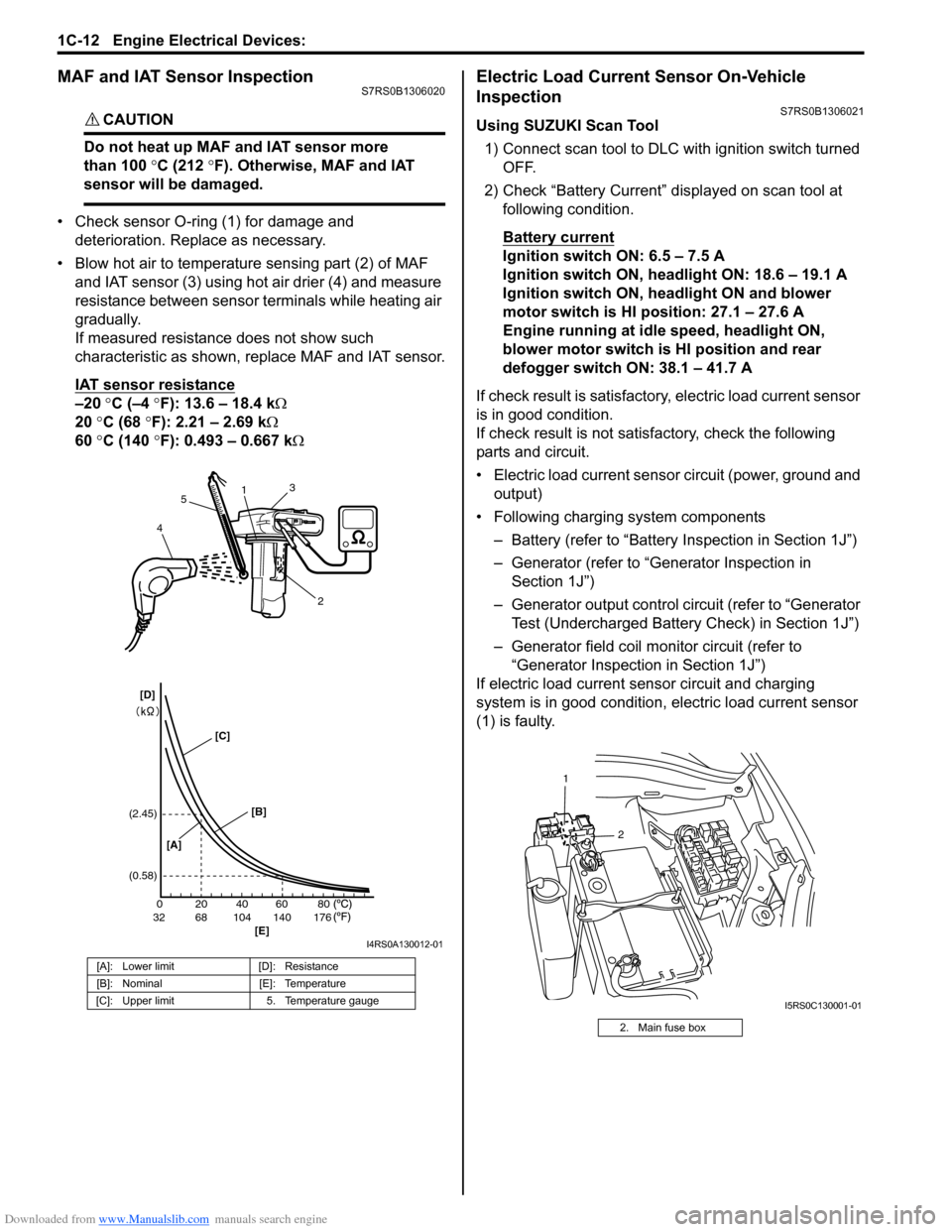
• Check sensor O-ring (1) for damage and deterioration. Replace as necessary.
• Blow hot air to temperature sensing part (2) of MAF and IAT sensor (3) using hot air drier (4) and measure
resistance between sensor terminals while heating air
gradually.
If measured resistance does not show such
characteristic as shown, replace MAF and IAT sensor.
IAT sensor resistance
–20 °C (–4 °F): 13.6 – 18.4 k Ω
20 °C (68 °F): 2.21 – 2.69 k Ω
60 °C (140 °F): 0.493 – 0.667 k Ω
Electric Load Current Sensor On-Vehicle
Inspection
S7RS0B1306021
Using SUZUKI Scan Tool
1) Connect scan tool to DLC with ignition switch turned OFF.
2) Check “Battery Current” displayed on scan tool at following condition.
Battery current
Ignition switch ON: 6.5 – 7.5 A
Ignition switch ON, headlight ON: 18.6 – 19.1 A
Ignition switch ON, headlight ON and blower
motor switch is HI position: 27.1 – 27.6 A
Engine running at idle speed, headlight ON,
blower motor switch is HI position and rear
defogger switch ON: 38.1 – 41.7 A
If check result is satisfactory, electric load current sensor
is in good condition.
If check result is not satisf actory, check the following
parts and circuit.
• Electric load current sensor circuit (power, ground and output)
• Following charging system components
– Battery (refer to “Battery Inspection in Section 1J”)
– Generator (refer to “Generator Inspection in Section 1J”)
– Generator output control ci rcuit (refer to “Generator
Test (Undercharged Battery Check) in Section 1J”)
– Generator field coil monitor circuit (refer to “Generator Inspection in Section 1J”)
If electric load current sensor circuit and charging
system is in good condition, electric load current sensor
(1) is faulty.
[A]: Lower limit [D]: Resistance
[B]: Nominal [E]: Temperature
[C]: Upper limit 5. Temperature gauge
200
6832104 140 17640 60 80
(2.45)
(0.58)
1
2
3
4 5
[A] [B]
[E]
[C]
[D]
I4RS0A130012-01
2. Main fuse box
2
1
I5RS0C130001-01
Page 302 of 1496

Downloaded from www.Manualslib.com manuals search engine 1D-17 Engine Mechanical:
Engine Assembly Removal and InstallationS7RS0B1406011
NOTE
After replacing electric throttle body
assembly, perform calibration of throttle
valve referring to “Electric Throttle Body
System Calibration in Section 1C”.
Removal1) Relieve fuel pressure according to “Fuel Pressure Relief Procedure in Section 1G”.
2) Disconnect negative and pos itive cable at battery.
3) Remove battery and tray.
4) Remove engine hood after disconnecting windshield washer hose.
5) Remove right and left side engine under covers.
6) Remove A/C compressor belt by referring to “Compressor Drive Belt Remo val and Installation in
Section 7B” or “Compressor Drive Belt Removal and
Installation in Section 7B”.
7) Drain engine oil, transaxle oil and coolant.
8) Remove cowl top plate referring to “Cowl Top Components in Section 9K”.
9) Remove air cleaner assembly referring to “Air Cleaner Components”.
10) With hose connected, detach A/C compressor from its bracket (A/C model) referring to “Compressor
Assembly Removal and Installation in Section 7B” or
“Compressor Assembly Removal and Installation in
Section 7B”.
CAUTION!
Suspend removed A/C compressor at a place
where no damage will be caused during
removal and installation of engine assembly.
11) Remove intake manifold rear stiffener (1) from intake manifold and cylinder block. 12) Disconnect the following electric wires:
• MAP sensor (1)
• ECT sensor (2)
•EGR valve (3)
• CMP sensor (4)
• Electric throttle body assembly (5)
• Ignition coil assembly (6)
• Injectors (7)
• Heated oxygen sensor No. 2 (8) and No. 1 (9)
• Oil control valve (10)
• Engine oil pressure switch (11)
• CKP sensor (12)
• Knock sensor (13)
• Back up light switch (14)
• Generator (15)
• Starting motor (16)
• Ground terminal (17) from intake manifold
• Battery ground terminal (18) from exhaust manifold
• Battery ground cable (19) from transaxle
• Magnet clutch switch of A/C compressor (A/C model)
• Each wire harness clamps
• Output shaft speed sensor (VSS) (34) (A/T model)
• Solenoid valve (33) (A/T model)
• Transmission range sensor (32) (A/T model)
• Input shaft speed sensor (31) (A/T model)
13) Remove fuse box from its bracket.
14) Disconnect the following cables: • Gear select control cable (23) (M/T model)
• Gear shift control cable (24) (M/T model)
• A/T select cable (A/T model)
15) Disconnect the following hoses: • Brake booster hose (26) from intake manifold
• Radiator inlet and outlet hoses (20) from each pipe
• Heater inlet and outlet hoses (21) from each pipe
• Fuel feed hoses (22) from fuel feed pipe
• EVAP canister purge valve hose (30) from purge pipe
• A/T fluid cooler hoses (A/T model)
16) With hose connected, detach clutch operating cylinder (25). (M/T model)
CAUTION!
Suspend removed clutch operating cylinder
at a place where no damage will be caused
during removal and installation of engine
assembly.
1
I6RS0B141014-01
Page 541 of 1496
Downloaded from www.Manualslib.com manuals search engine ABS: 4E-2
General Description
ABS DescriptionS7RS0B4501001
The ABS (Antilock Brake System) controls the fluid
pressure applied to the wheel cylinder of each brake
from the master cylinder so that each wheel is not locked
even when hard braking is applied.
This ABS has also the following function.
While braking is applied, but before ABS control
becomes effective, braking force is distributed between
the front and rear so as to prevent the rear wheels from
being locked too early for better stability of the vehicle.
The main component parts of this ABS include the
following parts in addition to those of the conventional
brake system.
• Wheel speed sensor which senses revolution speed of each wheel and outputs its signal.
• ABS warning light which light s to inform abnormality
when system fails to operate properly.
• ABS hydraulic unit / cont rol module assembly is
incorporated ABS co ntrol module, ABS hydraulic unit
(actuator assembly), solenoid valve power supply
driver (transistor), solenoid valve driver (transistor),
pump motor driver (transistor).
– ABS control module which sends operation signal to ABS hydraulic unit to control fluid pressure
applied to each wheel cylinder based on signal
from each wheel speed sensor so as to prevent
wheel from locking.
– ABS hydraulic unit which operates according to signal from ABS control module to control fluid
pressure applied to wheel cylinder of each 4
wheels.
– Solenoid valve power supp ly driver (transistor)
which supplies power to solenoid valve in ABS
hydraulic unit.
– Solenoid valve driver (transistor) which controls each solenoid valves in ABS hydraulic unit.
– Pump motor driver (transistor) which supplies power to pump motor in ABS hydraulic unit.
This ABS is equipped with Electronic Brake force
Distribution (EBD) system that controls a fluid pressure
of rear wheels to best condition, which is the same
function as that of proportion ing valve, by the signal from
wheel sensor independently of change of load due to
load capacity and so on. An d if the EBD system fails to
operate properly, the brake warning light lights to inform
abnormality.
ABS Hydraulic Unit / Control Module Assembly
Description
S7RS0B4501002
ABS control module is a component of ABS hydraulic
unit / control module asse mbly and has the following
functions.
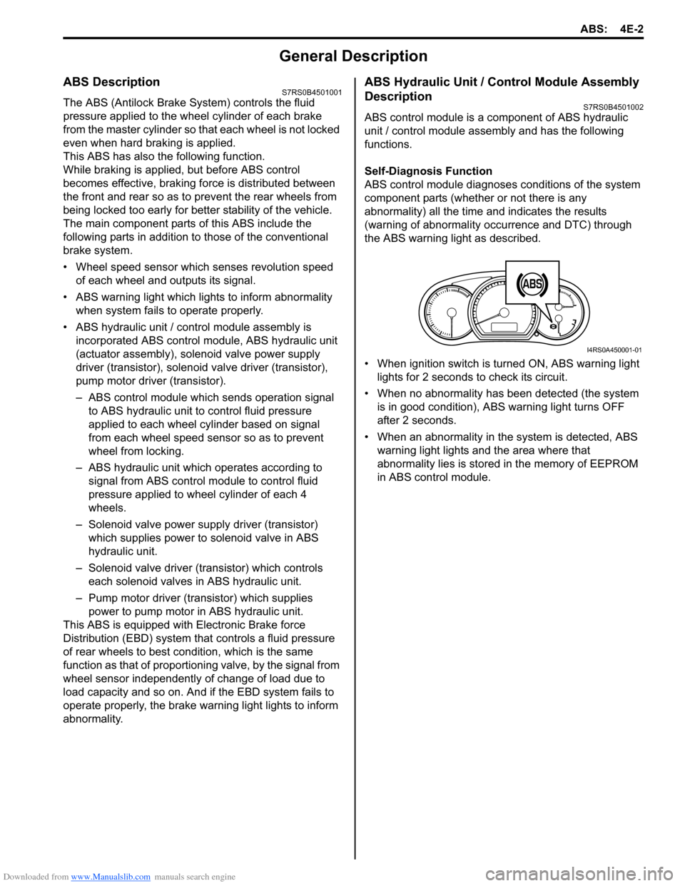
Self-Diagnosis Function
ABS control module diagnose s conditions of the system
component parts (whether or not there is any
abnormality) all the time and indicates the results
(warning of abnormality occurrence and DTC) through
the ABS warning light as described.
• When ignition switch is turned ON, ABS warning light lights for 2 seconds to check its circuit.
• When no abnormality has been detected (the system is in good condition), ABS warning light turns OFF
after 2 seconds.
• When an abnormality in th e system is detected, ABS
warning light lights and the area where that
abnormality lies is stored in the memory of EEPROM
in ABS control module.
1
I4RS0A450001-01
Page 543 of 1496
Downloaded from www.Manualslib.com manuals search engine ABS: 4E-4
Schematic and Routing Diagram
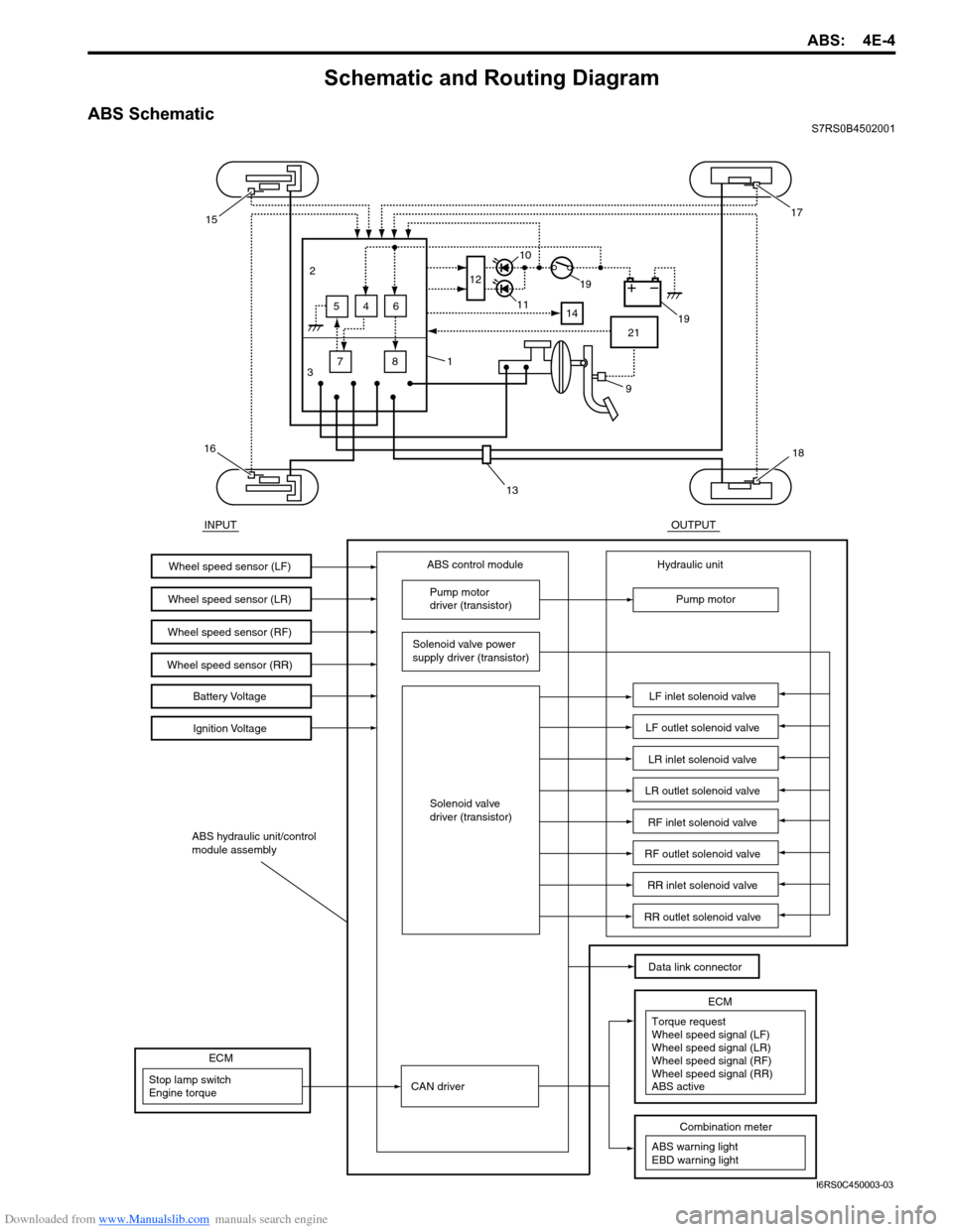
ABS SchematicS7RS0B4502001
INPUTOUTPUT
ABS control moduleWheel speed sensor (LF)
Wheel speed sensor (LR)
Wheel speed sensor (RF)Battery Voltage
Ignition Voltage
Pump motor
driver (transistor)
Solenoid valve power
supply driver (transistor)
Solenoid valve
driver (transistor) Hydraulic unit
Pump motor
LF inlet solenoid valve
LF outlet solenoid valve
LR inlet solenoid valve
LR outlet solenoid valve
RF inlet solenoid valve
RF outlet solenoid valve
RR inlet solenoid valve
RR outlet solenoid valve
Data link connector
ABS hydraulic unit/control
module assembly
Wheel speed sensor (RR)
3 7
2
645
8 12
14
21
15
16
1
13
18
17
19
19
11
10
9
CAN driverStop lamp switch
Engine torque
ECM
ABS warning light
EBD warning light
Combination meter
Torque request
ECMWheel speed signal (LF)
Wheel speed signal (LR)
Wheel speed signal (RF)
Wheel speed signal (RR)
ABS active
I6RS0C450003-03