2007 SUZUKI SWIFT Fuse box connector
[x] Cancel search: Fuse box connectorPage 246 of 1496

Downloaded from www.Manualslib.com manuals search engine 1A-196 Engine General Information and Diagnosis:
5Main relay circuit check
1) Connect connectors to ECM with ignition switch turned
OFF.
2) Turn ignition switch to ON position.
3) Measure voltage between “E23-60” terminal of ECM connector and body ground.
Is voltage 0 – 1 V? Go to Step 7. Go to Step 6.
6 ECM ground circuit check
1) Turn ignition switch to OFF position.
2) Disconnect connectors from ECM.
3) Measure resistance between each “E23-31”, “C37-58”,
“C37-15” and “C37-30” terminals of ECM connector and
body ground.
Is resistance 1
Ω or less? Substitute a known-
good ECM and recheck.
“BLK/ORN” or “BLK”
wire is open or high
resistance circuit.
7 Main relay circuit check
1) Disconnect connectors from ECM with ignition switch
turned OFF.
2) Using service wire, ground “E23-60” terminal of ECM connector and measure voltage between each “E23-1”
and “E23-16” terminals of ECM connector and body
ground.
Is voltage 10 – 14 V? Go to Step 11. Go to Step 8.
8 Main relay circuit check
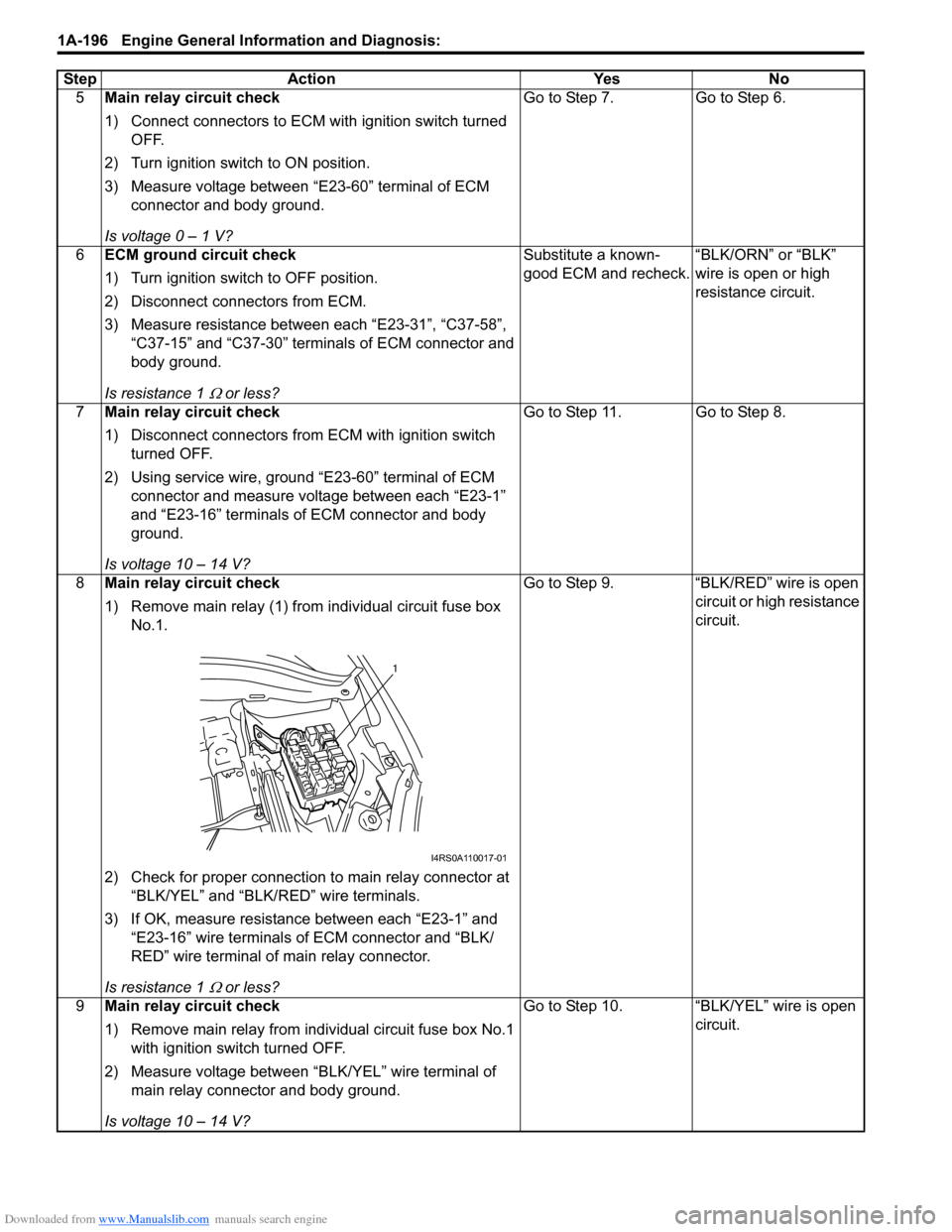
1) Remove main relay (1) from individual circuit fuse box
No.1.
2) Check for proper connection to main relay connector at “BLK/YEL” and “BLK/RED” wire terminals.
3) If OK, measure resistance between each “E23-1” and “E23-16” wire terminals of ECM connector and “BLK/
RED” wire terminal of main relay connector.
Is resistance 1
Ω or less? Go to Step 9. “BLK/RED” wire is open
circuit or high resistance
circuit.
9 Main relay circuit check
1) Remove main relay from individual circuit fuse box No.1
with ignition swit ch turned OFF.
2) Measure voltage between “BLK/YEL” wire terminal of main relay connector and body ground.
Is voltage 10 – 14 V? Go to Step 10. “BLK/YEL” wire is open
circuit.
Step Action Yes No
1
I4RS0A110017-01
Page 251 of 1496

Downloaded from www.Manualslib.com manuals search engine Engine General Information and Diagnosis: 1A-201
Troubleshooting
NOTE
When measuring circuit voltage, resistance and/or pulse signal at ECM connector, connect the special
tool to ECM and/or the ECM connectors referri ng to “Inspection of ECM and Its Circuits”.
StepAction YesNo
1 Fuel pump control system check for operation
Is fuel pump heard to operate 2 sec. after ignition switch is
turned ON? Fuel pump circuit is in
good condition.
Go to Step 2.
2 Fuel pump relay po wer supply check
1) Disconnect fuel pump relay from individual circuit fuse box No.1 with ignition switch turned OFF.
2) Check for proper connection to fuel pump relay at each terminal.
3) If OK, turn ON ignition switch, measure voltage between “BLK/WHT” wire terminal of fuel pump relay connector
and engine ground.
Is voltage 10 – 14 V? Go to Step 3.
“BLK/WHT” wire is open
or shorted to ground
circuit.
3 Fuel pump relay po wer supply check
1) Turn ON ignition switch, measure voltage between “BLK/ RED” wire terminal of fuel pump relay connector and
engine ground.
Is voltage 10 – 14 V? Go to Step 4.
“BLK/RED” wire is open
circuit.
4 Fuel pump relay check
1) Check fuel pump relay referring to “Main Relay, Fuel
Pump Relay and Starting Moto r Control Relay Inspection
in Section 1C”.
Is relay in good condition? Go to Step 5.
Faulty relay.
5 Fuel pump relay drive signal check
1) Connect fuel pump relay to individual circuit fuse box
No.1.
2) Connect voltmeter between “E23-15” terminal of ECM connector and vehicle body ground.
3) Measure voltage 2 second after ignition switch is turned ON.
Is voltage 10 – 14 V? Go to Step 6.
“GRN/WHT” wire is
open circuit or shorted
to ground circuit.
I2RH01110132-01
Page 259 of 1496

Downloaded from www.Manualslib.com manuals search engine Engine General Information and Diagnosis: 1A-209
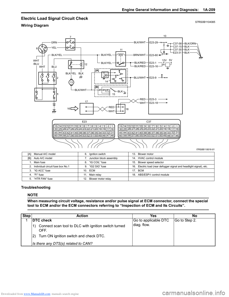
Electric Load Signal Circuit CheckS7RS0B1104085
Wiring Diagram
Troubleshooting
NOTE
When measuring circuit voltage, resistance and/or pulse signal at ECM connector, connect the special
tool to ECM and/or the ECM connectors referri ng to “Inspection of ECM and Its Circuits”.
BLK/WHT
BLK/RED
WHT
BRN/WHT
12V5V
11
BLK/YELBLK/YEL
BLK/YEL
BLKBLKBLK
BLK/ORN
10
18
17
BLU/WHT
15
WHTRED
43
YEL
5
13
BLK/WHT
BLKBLK/YEL
GRN
WHT
/BLU
BLU
16
2
6
7
12
8
9
BLK
WHT
RED
E23-29
E23-60
E23-1E23-16
E23-9
E23-3E23-18
C37-58C37-15
E23-31C37-30
BLK/RED
[A]
[B]
E23 C37
34
1819
567
10
11
17
20
47 46
495051
2122
52 16
25 9
24
14
29
5557 54 53
59
60 58 2
262728
15
30
56 4832 31
34353637
4042 39 38
44
45 43 41 331
1213
238
34
1819
567
10
11
17
20
47 46
495051
2122
52 16
25 9
24
14
29
5557 54 53
59
60 58 2
262728
15
30
56 4832 31
34353637
4042 39 38
44
45 43 41 331
12
13
238
1
14
I7RS0B110016-01
[A]: Manual A/C model
6. Ignition switch13. Blower motor
[B]: Auto A/C model 7. Junction block assembly14. HVAC control module
1. Main fuse 8. “IG COIL” fuse15. Blower speed selector
2. Individual circuit fuse box No.1 9. “IG2 SIG” fuse16. Electric load (rear defogger signal and headlight signal), etc.
3. “IG ACC” fuse 10. ECM17. BCM
4. “FI” fuse 11. Main relay18. ABS/ESP® control module
5. “HTR FAN” fuse 12. Blower motor relay
StepAction YesNo
1 DTC check
1) Connect scan tool to DLC with ignition switch turned
OFF.
2) Turn ON ignition switch and check DTC.
Is there any DTS(s) related to CAN? Go to applicable DTC
diag. flow.
Go to Step 2.
Page 262 of 1496

Downloaded from www.Manualslib.com manuals search engine 1A-212 Engine General Information and Diagnosis:
Troubleshooting
WARNING!
Keep hands, tools, and clothing away from engine cooling fan to help prevent personal injury. This fan
is electric and can come on whether or not the engi ne is running. The fan can start automatically in
response to the ECT sensor with the ig nition switch at the “ON” position.
NOTE
When measuring circuit voltage, resistance and/or pulse signal at ECM connector, connect the special
tool to ECM and/or the ECM connectors referri ng to “Inspection of ECM and Its Circuits”.
StepAction YesNo
1 Is there DTC(s) of ECT sensor circuit (DTC P0116 / P0117 /
P0118) and/or radiator cooling fan circuit (DTC P0480)? Go to corresponding
DTC flow.Go to Step 2.
2 Low speed radiator cooling fan control circuit check
1) Connect scan tool to DLC with ignition switch turned
OFF.
2) Start engine and select “DATA LIST” mode on scan tool.
3) Warm up engine until coolant temp. is 97.5 °C, 207.5 °F
or higher and A/C switch turns OFF (if equipped with A/
C). (If engine coolant temp. dose not rise, check engine
cooling system or ECT sensor.)
Is radiator cooling fan started at low speed when engine
coolant temp. reached above temp.? Radiator cooling fan low
speed control system is
in good condition.
Perform from Step 2 to
Step 8 in DTC P0480
diag. flow. If OK, Go to
Ste p 3.
3 Radiator cooling fan control check
1) Disconnect radiator cooling fan control relays No. 2, and
No. 3 from individual circuit fuse box No.1 with ignition
switch turned OFF.
2) Run engine when ECT is over 97.5 °C, 207.5 °F.
3) Measure voltage between vehicle body ground and “BLU/RED” wire terminal of disconnected radiator
cooling fan motor connector.
Is voltage 10 – 14 V? Go to Step 4.
“BLU/RED” wire is open
or high resistance
circuit.
4 Check radiator cooling fan wire circuit check
1) Turn ignition switch to OFF position.
2) Measure resistance between “BLK” wire terminal of
disconnected radiator coolin g fan motor connector and
vehicle body ground.
Is resistance below 1
Ω? Go to Step 5. “BLK” wire is open or
high resistance circuit.
5 Radiator cooling fan check
1) Check radiator cooling fan referring to “Radiator Cooling
Fan Motor On-Vehicle Inspection in Section 1F”.
Is it in good condition? Substitute a known-
good ECM and recheck.
Faulty radiator cooling
fan.
Page 265 of 1496

Downloaded from www.Manualslib.com manuals search engine Engine General Information and Diagnosis: 1A-215
7Radiator cooling fan No. 2 wire circuit check
1) Turn ON ignition switch.
2) Measure voltage between “BLU/BLK” wire terminal of
disconnected radiator cooling fan control relay No. 2
connector and vehicle body ground.
Is voltage 0 V? Go to Step 8. “BLU/BLK” wire is
shorted to power supply
circuit.
8 Radiator cooling fan control No. 2 check
1) Connect radiator cooling fan control relay No. 2 to
individual circuit fuse box No.1 with ignition switch
turned OFF.
2) Run engine when ECT is over 102.5 °C, 216.5 °F.
3) Measure voltage between vehicle body ground and “BLU/BLK” wire terminal of disconnected radiator
cooling fan motor connector.
Is voltage 10 – 14 V? Go to Step 10. Go to Step 9.
9 Radiator cooling fan control relay No.2 check
1) Remove radiator cooling fan control relay No.2 with
ignition switch turned OFF.
2) Check radiator cooling fan control relay No.2 referring to “Radiator Cooling Fan Relay Inspection in Section 1F”.
Is it in good condition? “BLU/BLK” wire is open
or high resistance
circuit.
Faulty radiator cooling
fan control relay No.2.
10 Radiator cooling fan No. 3 wire circuit check
1) Remove radiator cooling fan control relay No.3 with
ignition switch turned OFF.
2) Measure resistance between vehicle body ground and “BLK” wire terminal of disconnected radiator cooling fan
control relay No. 3 connector in individual circuit fuse
box No.1.
Is resistance below 1
Ω? Go to Step 11. “BLK” wire is open or
high resistance circuit.
11 Radiator cooling fan control No. 3 check
1) Connect radiator cooling fan control relay No. 3 to
individual circuit fuse box No.1 with ignition switch
turned OFF.
2) Run engine when ECT is over 102.5 °C, 216.5 °F.
3) Measure resistance between vehicle body ground and “BLU/WHT” wire terminal of disconnected radiator
cooling fan motor connector.
Is resistance below 2
Ω? Go to Step 13. Go to Step 12.
12 Radiator cooling fan control relay No. 3 check
1) Remove radiator cooling fan control relay No.3 with
ignition switch turned OFF.
2) Check radiator cooling fan control relay No.3 referring to “Radiator Cooling Fan Relay Inspection in Section 1F”.
Is it in good condition? “BLU/WHT” wire is open
or high resistance
circuit.
Faulty radiator cooling
fan control relay No.3.
13 Radiator cooling fan check
1) Check radiator cooling fan referring to “Radiator Cooling
Fan Motor On-Vehicle Inspection in Section 1F”.
Is it in good condition? Substitute a known-
good ECM and recheck.
Faulty radiator cooling
fan.
Step
Action YesNo
Page 282 of 1496

Downloaded from www.Manualslib.com manuals search engine 1C-10 Engine Electrical Devices:
Knock Sensor Removal and InstallationS7RS0B1306016
Removal1) Disconnect negative (–) cable at battery.
2) Hoist vehicle.
3) Remove right side drive shaft referring to “Front Drive Shaft Assembly Removal and Installation in
Section 3A”.
4) Disconnect knock sensor connector (1).
5) Remove knock sensor (2) from cylinder block.
Installation
Reverse removal procedure for installation.
Tightening torque
Knock sensor (a): 22 N· m (2.2 kgf-m, 16.0 lb-ft)
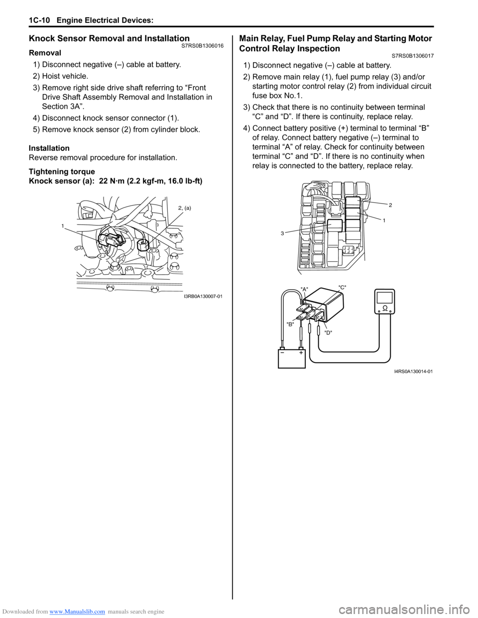
Main Relay, Fuel Pump Relay and Starting Motor
Control Relay Inspection
S7RS0B1306017
1) Disconnect negative (–) cable at battery.
2) Remove main relay (1), fuel pump relay (3) and/or
starting motor control relay (2) from individual circuit
fuse box No.1.
3) Check that there is no continuity between terminal “C” and “D”. If there is continuity, replace relay.
4) Connect battery positive (+ ) terminal to terminal “B”
of relay. Connect battery negative (–) terminal to
terminal “A” of relay. Ch eck for continuity between
terminal “C” and “D”. If t here is no continuity when
relay is connected to the battery, replace relay.
1 2, (a)
I3RB0A130007-01
"D"
"B" "A"
"C"
2
1
3
I4RS0A130014-01
Page 285 of 1496

Downloaded from www.Manualslib.com manuals search engine Engine Electrical Devices: 1C-13
Without Using SUZUKI Scan Tool1) Measure sensor voltage between “C37-23” terminal of ECM connector and vehicle body ground referring
to “Inspection of ECM and Its Circuits in Section 1A”.
If check result is satisfactory, electric load current
sensor is in good condition.
If check result is not satisfactory, check the following
parts and circuit.
• Electric load current sensor circuit (power, ground and output)
• Following charging system components – Battery (refer to “Battery Inspection in Section
1J”)
– Generator (refer to “Generator Inspection in Section 1J”)
– Generator output control circuit (refer to “Generator Test (Undercharged Battery Check)
in Section 1J”)
– Generator field coil monitor circuit (refer to “Generator Inspection in Section 1J”) If electric load current sensor circuit and charging
system is in good condition,
electric load current sensor
(1) is faulty.
Specifications
Tightening Torque SpecificationsS7RS0B1307001
Reference:
For the tightening torque of fastener not specified in this section, refer to “Fasteners Information in Section 0A”.
2. Main fuse box
2
1
I5RS0C130001-01
Fastening part
Tightening torque
Note
N ⋅mkgf-mlb-ft
ECM mounting bolt 8 0.8 6.0 �)
APP sensor assembly nut 5.5 0.55 4.0 �)
ECT sensor 15 1.5 11.0 �)
Heated oxygen sensor 45 4.5 32.5 �)
CMP sensor bolt 10 1.0 7.5 �)
CKP sensor bolt 10 1.0 7.5 �)
Knock sensor 22 2.2 16.0 �)
MAF and IAT sensor screw 1.5 0.15 1.1 �)
Page 395 of 1496

Downloaded from www.Manualslib.com manuals search engine Ignition System: 1H-3
Component Location
Ignition System Components LocationS7RS0B1803001
NOTE
The figure shows left-hand steering vehicle. For right-hand steering vehicle, parts with (*) are installed
at the opposite side.
16*
1
2
14
7
5 12 11
410
6
89
3 13*
15
17
I6RS0C180001-01
1. ECM 7. ECT sensor13. Data link connector
2. Ignition coil assembly for No.1 and No.4 spark plugs 8. MAF and IAT sensor 14. Battery fuse box
3. Ignition coil assembly for No.2 and No.3 spark plugs 9. Electric throttle body 15. Relay box
4. CMP sensor 10. Wheel speed sensor (VSS) 16. Junction block assembly
5. CKP sensor 11. High-tension cords
6. MAP sensor 12. Knock sensor