2007 SUZUKI SWIFT CAN junction connector
[x] Cancel search: CAN junction connectorPage 908 of 1496
Downloaded from www.Manualslib.com manuals search engine 6C-26 Power Assisted Steering System:
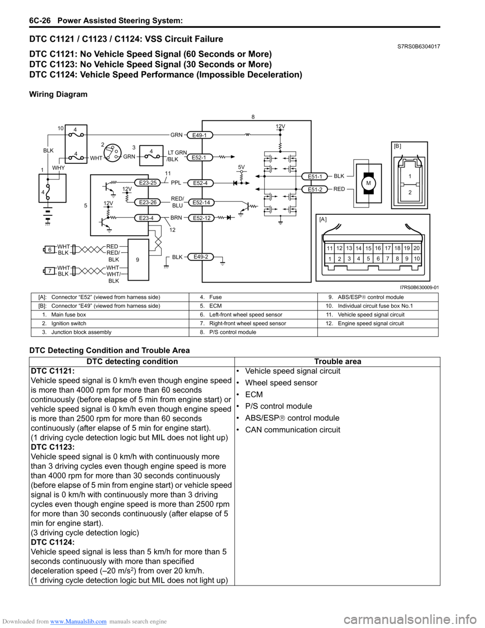
DTC C1121 / C1123 / C1124: VSS Circuit FailureS7RS0B6304017
DTC C1121: No Vehicle Speed Signal (60 Seconds or More)
DTC C1123: No Vehicle Speed Signal (30 Seconds or More)
DTC C1124: Vehicle Speed Performance (Impossible Deceleration)
Wiring Diagram
DTC Detecting Condition and Trouble Area
M
BRNRED/
BLU
BLK
RED
E52-14
E52-12
E23-4
E23-26
E23-25 E51-1
E51-2
[A ]
12
3
4 5 67
89
11
10
12 13
141516
17 18 19 20
5V
PPL
E52-4
8
5
12V
E49-2BLK
12V
12V
6REDRED/ BLKWHT
7WHTWHT/BLKWHTBLK BLK
111
2
[B ]
9
LT GRN
/BLKE52-1 E49-1
GRNGRNWHTBLK
WHY
10
3
4
4
4
4
1 2
12
I7RS0B630009-01
[A]: Connector “E52” (viewed from harness side)
4. Fuse9. ABS/ESP® control module
[B]: Connector “E49” (viewed from harness si de)5. ECM 10. Individual circuit fuse box No.1
1. Main fuse box 6. Left-front wheel speed sensor11. Vehicle speed signal circuit
2. Ignition switch 7. Right-front wheel speed sensor 12. Engine speed signal circuit
3. Junction block assembly 8. P/S control module
DTC detecting condition Trouble area
DTC C1121:
Vehicle speed signal is 0 km/h even though engine speed
is more than 4000 rpm for more than 60 seconds
continuously (before elapse of 5 min from engine start) or
vehicle speed signal is 0 km/h even though engine speed
is more than 2500 rpm for more than 60 seconds
continuously (after elapse of 5 min for engine start).
(1 driving cycle detection logic but MIL does not light up)
DTC C1123:
Vehicle speed signal is 0 km/h with continuously more
than 3 driving cycles even though engine speed is more
than 4000 rpm for more than 30 seconds continuously
(before elapse of 5 min from engine start) or vehicle speed
signal is 0 km/h with continuously more than 3 driving
cycles even though engine speed is more than 2500 rpm
for more than 30 seconds continuously (after elapse of 5
min for engine start).
(3 driving cycle detection logic)
DTC C1124:
Vehicle speed signal is less than 5 km/h for more than 5
seconds continuously with more than specified
deceleration speed (–20 m/s
2) from over 20 km/h.
(1 driving cycle detection logic but MIL does not light up) • Vehicle speed signal circuit
• Wheel speed sensor
•ECM
• P/S control module
• ABS/ESP®
control module
• CAN communication circuit
Page 1010 of 1496
Downloaded from www.Manualslib.com manuals search engine 7B-62 Air Conditioning System: Automatic Type
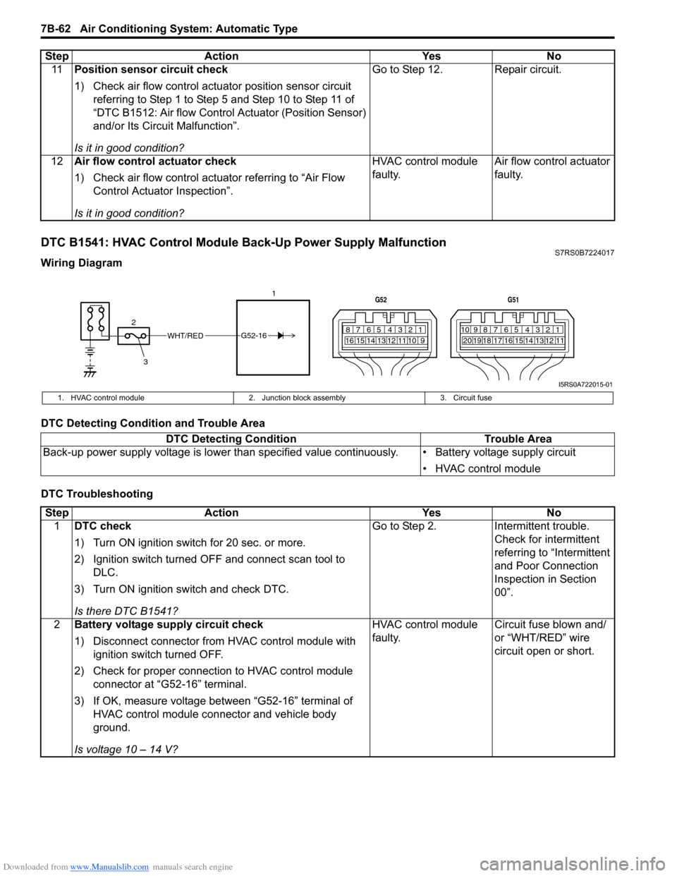
DTC B1541: HVAC Control Module Back-Up Power Supply MalfunctionS7RS0B7224017
Wiring Diagram
DTC Detecting Condition and Trouble Area
DTC Troubleshooting11
Position sensor circuit check
1) Check air flow control actuator position sensor circuit
referring to Step 1 to Step 5 and Step 10 to Step 11 of
“DTC B1512: Air flow Control Actuator (Position Sensor)
and/or Its Circuit Malfunction”.
Is it in good condition? Go to Step 12. Repair circuit.
12 Air flow control actuator check
1) Check air flow control actuator referring to “Air Flow
Control Actuator Inspection”.
Is it in good condition? HVAC control module
faulty.
Air flow control actuator
faulty.
Step Action Yes No
WHT/RED
2 17812910
65 431516 14 13 12 11
G52
789101920121112
65 431718 16 15 14 13
G51
3
G52-16
I5RS0A722015-01
1. HVAC control module
2. Junction block assembly 3. Circuit fuse
DTC Detecting Condition Trouble Area
Back-up power supply voltage is lo wer than specified value continuously. • Battery voltage supply circuit
• HVAC control module
StepAction YesNo
1 DTC check
1) Turn ON ignition switch for 20 sec. or more.
2) Ignition switch turned OF F and connect scan tool to
DLC.
3) Turn ON ignition switch and check DTC.
Is there DTC B1541? Go to Step 2.
Intermittent trouble.
Check for intermittent
referring to “Intermittent
and Poor Connection
Inspection in Section
00”.
2 Battery voltage supply circuit check
1) Disconnect connector from HVAC control module with
ignition switch turned OFF.
2) Check for proper connection to HVAC control module connector at “G52-16” terminal.
3) If OK, measure voltage between “G52-16” terminal of HVAC control module connector and vehicle body
ground.
Is voltage 10 – 14 V? HVAC control module
faulty.
Circuit fuse blown and/
or “WHT/RED” wire
circuit open or short.
Page 1012 of 1496
Downloaded from www.Manualslib.com manuals search engine 7B-64 Air Conditioning System: Automatic Type
DTC Detecting Condition and Trouble Area
DTC Troubleshooting
DTC B1552: Serial Communication Signal MalfunctionS7RS0B7224020
DTC Detecting Condition and Trouble AreaDTC detecting condition Trouble area
Serial communication signal is higher than or lower than specified value for
specified time continuously. • Serial communication line of BCM
• BCM (included in junction block
assembly)
• Information display
• HVAC control module
Step Action YesNo
1 DTC check
1) Connect scan tool to DLC with ignition switch turned
OFF.
2) Disconnect connector from information display.
3) Turn ignition switch ON and check DTC.
Is there DTC B1551? Go to Step 2.
Information display
faulty.
2 Wire harness check
1) Disconnect connectors from BCM and HVAC control
module.
2) Measure resistance between “G37-11” terminal of BCM connector and “G51-7” terminal of HVAC control module
connector.
Is resistance below 5
Ω? Go to Step 3. “YEL” wire open or high
resistance circuit.
3 Wire harness check
1) Measure resistance between “G51-7” terminal of HVAC
control module connector and vehicle body ground.
Is resistance infinity? Go to Step 4. “YEL” wire shorted to
ground circuit.
4 Wire harness check
1) Measure voltage between “G51-7” terminal of HVAC
control module connector and vehicle body ground with
ignition switch turned ON.
Is voltage 0 V? Go to Step 5. “YEL” wire shorted to
other circuit.
5 Serial communication signal check
1) Connect connectors to BCM and HVAC control module.
2) Using oscilloscope, check that serial communication
signal is outputted referring to “Reference waveform
No.8” of “Inspection of BCM and its Circuits in Section
10B”.
Is serial communication signal outputted at “G37-11”
terminal of BCM connector? HVAC control module
faulty.
BCM (included in
junction block
assembly) faulty.
DTC detecting condition
Trouble area
Data received by HVAC control module from BCM is erroneous continuously. • BCM (included in junction block assembly)
• HVAC control module
Page 1013 of 1496
Downloaded from www.Manualslib.com manuals search engine Air Conditioning System: Automatic Type 7B-65
DTC Troubleshooting
DTC B1553: CAN Communication Signal MalfunctionS7RS0B7224021
DTC Detecting Condition and Trouble Area
DTC Troubleshooting
DTC B1557: Vehicle Speed Sensor Signal MalfunctionS7RS0B7224022
DTC Detecting Condition and Trouble Area
DTC TroubleshootingStep Action Yes No
1 Serial communication signal data check
1) Connect scan tool to DLC with ignition switch turned
OFF.
2) Start engine and select “DATA LIST” mode on scan tool.
3) Check “Refrigerant Pressure”, “Vehicle Speed”, “Coolant Temp” and “Outside Air Temp” varies displayed on scan
tool.
Is displayed each va ries described varies in “Scan Tool
Data”? Intermittent trouble.
Check for intermittent
referring to “Intermittent
and Poor Connection
Inspection in Section
00”.
Go to Step 2.
2 Serial communication signal check
1) Connect connectors to BCM and HVAC control module.
2) Using oscilloscope, check that serial communication
signal is outputted referring to “Reference waveform
No.8” of “Inspection of BCM and its Circuits in Section
10B”.
Is serial communication signal outputted at “G37-11”
terminal of BCM connector? HVAC control module
faulty.
BCM (included in
junction block
assembly) faulty.
DTC detecting condition
Trouble area
HVAC control module receives error code fr om BCM continuously.• CAN communication circuit
• BCM (included in junction block assembly)
•ECM
• HVAC control module
Step Action YesNo
1 DTC check
1) Connect scan tool to DLC with ignition switch turned
OFF.
2) Check ECM and BCM for DTC.
Is there DTC(s)? Go to applicable DTC
diag. flow.
Substitute a known-
good HVAC control
module and recheck.
DTC detecting condition
Trouble area
HVAC control module receives error code from BCM continuously. • VSS circuit
• VSS
• HVAC control module
Step Action YesNo
1 DTC check
1) Connect scan tool to DLC with ignition switch turned
OFF.
2) Check ECM for DTC.
Is there DTC P0500? Go to “DTC P0480: Fan
1 (Radiator Cooling
Fan) Control Circuit in
Section 1A”.
Substitute a known-
good HVAC control
module and recheck.
Page 1055 of 1496
Downloaded from www.Manualslib.com manuals search engine Air Bag System: 8B-17
CAUTION!
• Be sure to perform “Air Bag Diagnostic System Check” before starting diagnosis according to flow.
• When measurement of resistance or voltage is required in this flow, use a tester along with a correct terminal adapter from special tool (Connector test adapter kit).
• When a check for proper connection is required, refer to “Inspection of Intermittent and Poor Connections”.
• If there is open circuit in the air bag wire harnes s, connector or terminal is found damaged, replace
the wire harness, connector and terminal as an assembly.
Flow Test Description
Check for short circuit between diag nosis switch circuit and ground.
Troubleshooting
NOTE
Upon completion of inspection and repair work, perform the following items.
• Reconnect all air bag system components and ensure all components are properly mounted.
• Repeat “Air Bag Diagnostic System Check” to confirm that the trouble has been corrected.
DTC B1013: SDM faultS7RS0B8204010
DTC Will Set when
An internal SDM fault is detected by SDM.
NOTE
DTC B1013 can never be cleared once it has been set.
DTC Troubleshooting 1) Turn ignition switch OFF.
2) Replace SDM.
3) Repeat “Air Bag Diagnostic System Check”.
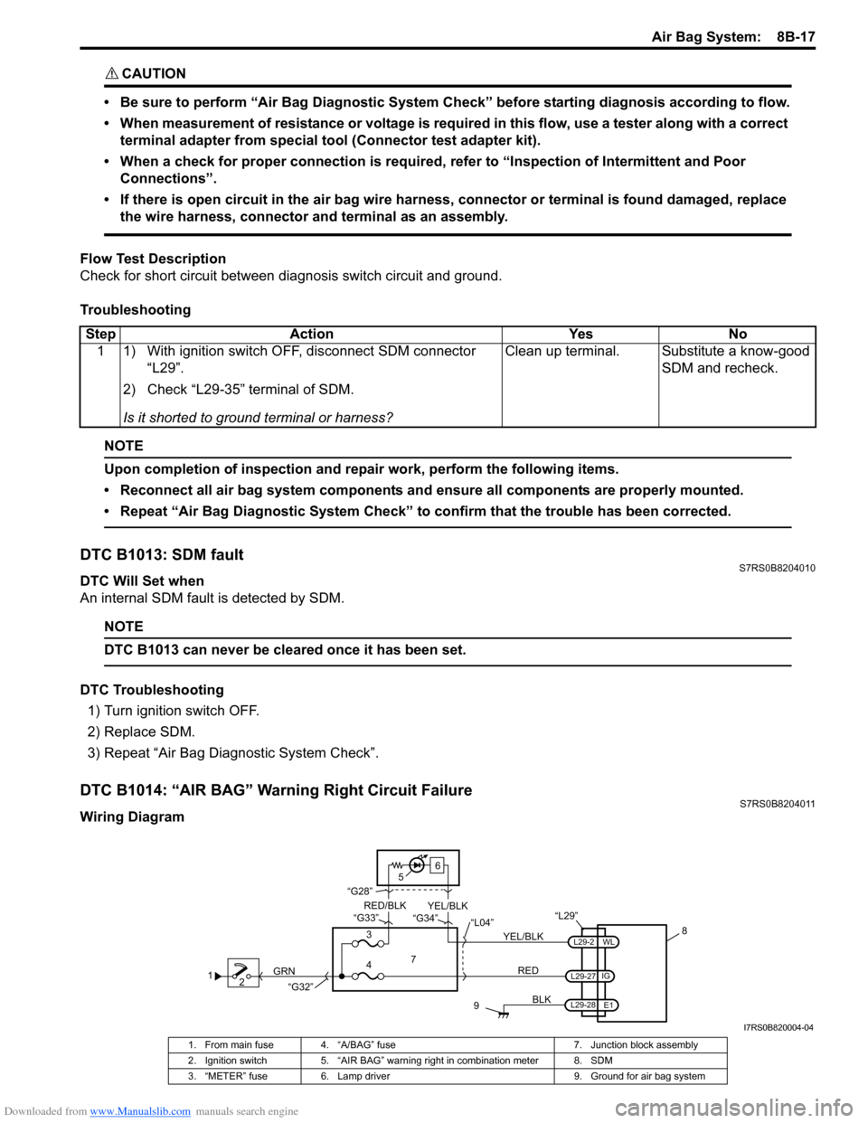
DTC B1014: “AIR BAG” Warning Right Circuit FailureS7RS0B8204011
Wiring DiagramStep Action Yes No
1 1) With ignition switch OFF, disconnect SDM connector “L29”.
2) Check “L29-35” terminal of SDM.
Is it shorted to ground terminal or harness? Clean up terminal. Substitute a know-good
SDM and recheck.
12 GRN
9
BLK
L29-2
L29-27
L29-28 IG
E1
WL
8
“L29”
RED
7
3
4 “L04”
“G34”
“G33”
“G28”
“G32”
5 6
YEL/BLK
YEL/BLK
RED/BLK
I7RS0B820004-04
1. From main fuse 4. “A/BAG” fuse
7. Junction block assembly
2. Ignition switch 5. “AIR BAG” warning right in combination meter 8. SDM
3. “METER” fuse 6. Lamp driver 9. Ground for air bag system
Page 1062 of 1496
Downloaded from www.Manualslib.com manuals search engine 8B-24 Air Bag System:
DTC B1027: Reusable Number ExceededS7RS0B8204017
DTC Will Set when
The SDM has not been replaced though the side-air bag developed several times in the past.
NOTE
DTC B1027 can never be cleared once it has been set.
DTC Trouble shooting1) Turn ignition switch OFF.
2) Replace SDM.
3) Repeat “Air Bag Diagnostic System Check”.
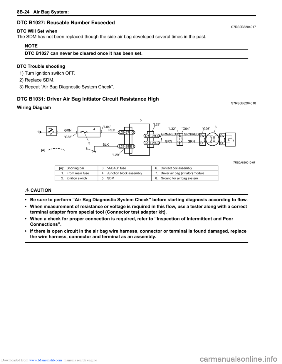
DTC B1031: Driver Air Bag Initiator Circuit Resistance HighS7RS0B8204018
Wiring Diagram
CAUTION!
• Be sure to perform “Air Bag Diagnostic System Check” before starting diagnosis according to flow.
• When measurement of resistance or voltage is required in this flow, use a tester along with a correct terminal adapter from special tool (Connector test adapter kit).
• When a check for proper connection is required, refer to “Inspection of Intermittent and Poor Connections”.
• If there is open circuit in the air bag wire harnes s, connector or terminal is found damaged, replace
the wire harness, connector and terminal as an assembly.
1 2
3
GRN
RED
8
BLK
L29-27
L29-28 IG
E1
4
“L29”
“L04”
“G32”
“L29”
L29-4
D+
L29-3
D-GRN
GRN/RED
GRN
GRN/RED 6
57
“G26”
“L32” “G04”
[A]
I7RS0A820010-07
[A]: Shorting bar 3. “A/BAG” fuse 6. Contact coil assembly
1. From main fuse 4. Junction block assembly 7. Driver air bag (inflator) module
2. Ignition switch 5. SDM 8. Ground for air bag system
Page 1172 of 1496
Downloaded from www.Manualslib.com manuals search engine 9A-1 Wiring Systems:
Body, Cab and Accessories
Wiring Systems
Precautions
Cautions in Body Electrical System ServicingS7RS0B9100001
When servicing the electric systems, observe the cautions described in “Precautions for Electrical Circuit Service in
Section 00” to protect electrical parts and to prevent a fire.
General Description
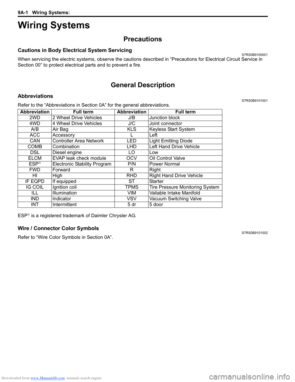
AbbreviationsS7RS0B9101001
Refer to the “Abbreviations in Sect ion 0A” for the general abbreviations.
ESP
® is a registered trademark of Daimler Chrysler AG.
Wire / Connector Color SymbolsS7RS0B9101002
Refer to “Wire Color Sy mbols in Section 0A”.
Abbreviation Full term Abbreviation Full term
2WD 2 Wheel Drive Vehicles J/B Junction block
4WD 4 Wheel Drive Vehicles J/C Joint connectorA/B Air Bag KLS Keyless Start System
ACC Accessory L Left
CAN Controller Area Network LED Light Emitting Diode
COMB Combination LHD Left Hand Drive Vehicle DSL Diesel engine LO Low
ELCM EVAP leak check module OCV Oil Control Valve ESP
®Electronic Stability Program P/N Power Normal
FWD Forward R Right HI High RHD Right Hand Drive Vehicle
IF EQPD If equipped ST Starter IG COIL Ignition coil TPMS Tire Pressure Monitoring System ILL Illumination VIM Valiable Intake Manifold
IND Indicator VSV Vacuum Switching Valve INT Intermittent 5 dr 5 door
Page 1320 of 1496
Downloaded from www.Manualslib.com manuals search engine 9D-3 Wipers / Washers:
Washer Tank and Washer Pump Removal and
Installation
S7RS0B9406002
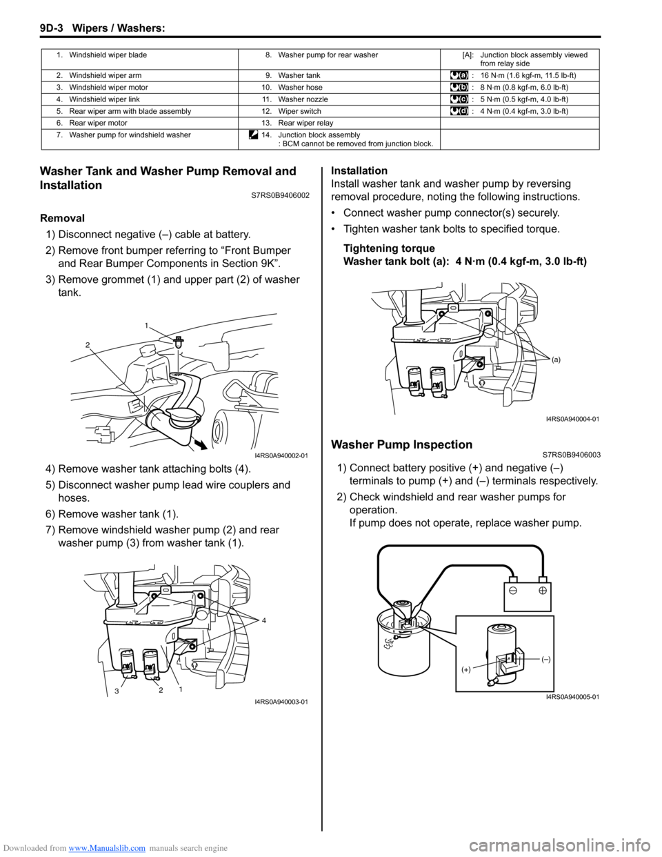
Removal1) Disconnect negative (–) cable at battery.
2) Remove front bumper referring to “Front Bumper and Rear Bumper Components in Section 9K”.
3) Remove grommet (1) and upper part (2) of washer tank.
4) Remove washer tank attaching bolts (4).
5) Disconnect washer pump lead wire couplers and hoses.
6) Remove washer tank (1).
7) Remove windshield washer pump (2) and rear washer pump (3) from washer tank (1). Installation
Install washer tank and washer pump by reversing
removal procedure, noting the following instructions.
• Connect washer pump connector(s) securely.
• Tighten washer tank bolts to specified torque.
Tightening torque
Washer tank bolt (a): 4 N·m (0.4 kgf-m, 3.0 lb-ft)
Washer Pump InspectionS7RS0B9406003
1) Connect battery positive (+) and negative (–) terminals to pump (+) and (–) terminals respectively.
2) Check windshield and rear washer pumps for
operation.
If pump does not operate, replace washer pump.
1. Windshield wiper blade 8. Washer pump for rear washer[A]: Junction block assembly viewed
from relay side
2. Windshield wiper arm 9. Washer tank: 16 N⋅m (1.6 kgf-m, 11.5 lb-ft)
3. Windshield wiper motor 10. Washer hose : 8 N⋅m (0.8 kgf-m, 6.0 lb-ft)
4. Windshield wiper link 11. Washer nozzle : 5 N⋅m (0.5 kgf-m, 4.0 lb-ft)
5. Rear wiper arm with blade assembly 12. Wiper switch : 4 N⋅m (0.4 kgf-m, 3.0 lb-ft)
6. Rear wiper motor 13. Rear wiper relay
7. Washer pump for windshield washer 14. Junction block assembly
: BCM cannot be removed from junction block.
1
2
I4RS0A940002-01
2 1 4
3
I4RS0A940003-01
(a)
I4RS0A940004-01
(–)
(+)
I4RS0A940005-01