2007 SUZUKI SWIFT engine wiring
[x] Cancel search: engine wiringPage 1119 of 1496
Downloaded from www.Manualslib.com manuals search engine Air Bag System: 8B-81
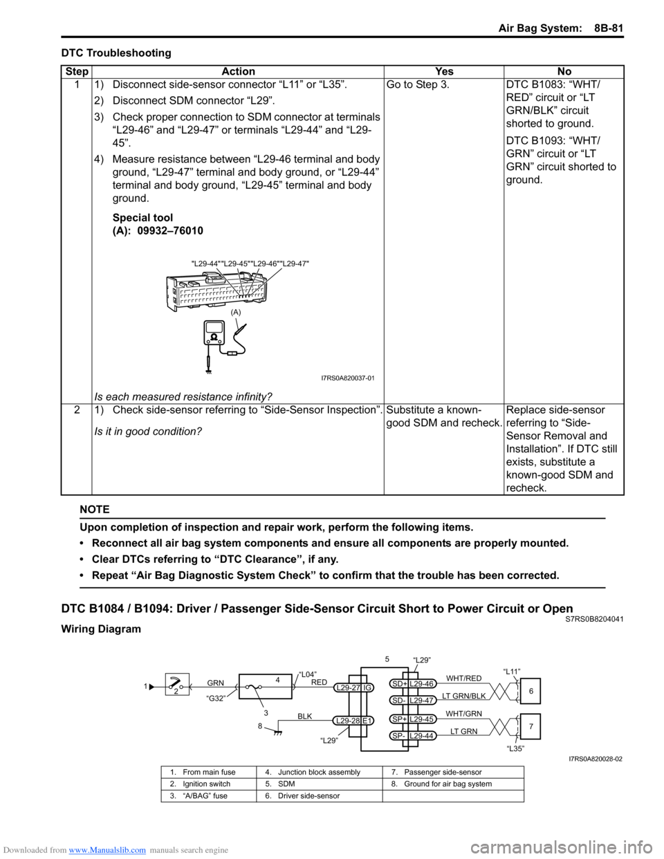
DTC Troubleshooting
NOTE
Upon completion of inspection and repair work, perform the following items.
• Reconnect all air bag system components and ensure all components are properly mounted.
• Clear DTCs referring to “DTC Clearance”, if any.
• Repeat “Air Bag Diagnostic System Check” to confirm that the trouble has been corrected.
DTC B1084 / B1094: Driver / Passenger Side-Sensor Circuit Short to Power Circuit or OpenS7RS0B8204041
Wiring DiagramStep Action Yes No
1 1) Disconnect side-sensor connector “L11” or “L35”.
2) Disconnect SDM connector “L29”.
3) Check proper connection to SDM connector at terminals “L29-46” and “L29-47” or terminals “L29-44” and “L29-
45”.
4) Measure resistance between “L29-46 terminal and body ground, “L29-47” terminal and body ground, or “L29-44”
terminal and body ground, “L29-45” terminal and body
ground.
Special tool
(A): 09932–76010
Is each measured resistance infinity? Go to Step 3. DTC B1083: “WHT/
RED” circuit or “LT
GRN/BLK” circuit
shorted to ground.
DTC B1093: “WHT/
GRN” circuit or “LT
GRN” circuit shorted to
ground.
2 1) Check side-sensor referring to “Side-Sensor Inspection”. Is it in good condition? Substitute a known-
good SDM and recheck.
Replace side-sensor
referring to “Side-
Sensor Removal and
Installation”. If DTC still
exists, substitute a
known-good SDM and
recheck.
"L29-45""L29-46""L29-47"
"L29-44"
(A)
I7RS0A820037-01
12
3
GRN
RED
8
BLK
L29-27
L29-28 IG
E1
4
“L29”
“L04”
“G32”
“L29”5
WHT/RED
LT GRN/BLKL29-46
SD+
L29-47
SD-6
“L11”
WHT/GRN
LT GRNL29-45
SP+
L29-44
SP-7
“L35”
I7RS0A820028-02
1. From main fuse 4. Junction blo ck assembly 7. Passenger side-sensor
2. Ignition switch 5. SDM 8. Ground for air bag system
3. “A/BAG” fuse 6. Driver side-sensor
Page 1122 of 1496
Downloaded from www.Manualslib.com manuals search engine 8B-84 Air Bag System:
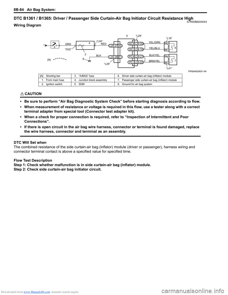
DTC B1361 / B1365: Driver / Passenger Side Curtain-Air Bag Initiator Circuit Resistance HighS7RS0B8204043
Wiring Diagram
CAUTION!
• Be sure to perform “Air Bag Diagnostic System Check” before starting diagnosis according to flow.
• When measurement of resistance or voltage is required in this flow, use a tester along with a correct terminal adapter from special tool (Connector test adapter kit).
• When a check for proper connection is required, refer to “Inspection of Intermittent and Poor Connections”.
• If there is open circuit in the air bag wire harnes s, connector or terminal is found damaged, replace
the wire harness, connector and terminal as an assembly.
DTC Will Set when
The combined resistance of the side curtain-air bag (inflator) module (driver or passenger), harness wiring and
connector terminal contact is above a specified value for specified time.
Flow Test Description
Step 1: Check whether malfunction is in side curtain-air bag (inflator) module.
Step 2: Check side curtain-air bag initiator circuit.
1 2
3
GRN
RED
8
BLK
L29-27
L29-28 IG
E1
4
“L29”
“L04”
“G32”
“L29”
L29-20
DC+
L29-19
DC-YEL/BLU
YEL/GRN
56
“L18”
L29-21
PC+
L29-22
PC-BRN/YEL BLK/YEL7
“L41”[A]
I7RS0A820031-04
[A]: Shorting bar 3. “A/BAG” fuse 6. Driver side curtain-air bag (inflator) module
1. From main fuse 4. Junction block assembly 7. Passenger side curtain-air bag (inflator) module
2. Ignition switch 5. SDM 8. Ground for air bag system
Page 1124 of 1496
Downloaded from www.Manualslib.com manuals search engine 8B-86 Air Bag System:
NOTE
Upon completion of inspection and repair work, perform the following items.
• Reconnect all air bag system components, ensure all components are properly mounted.
• Clear DTCs referring to “DTC Clearance”, if any.
• Repeat “Air Bag Diagnostic System Check” to confirm that the trouble has been corrected.
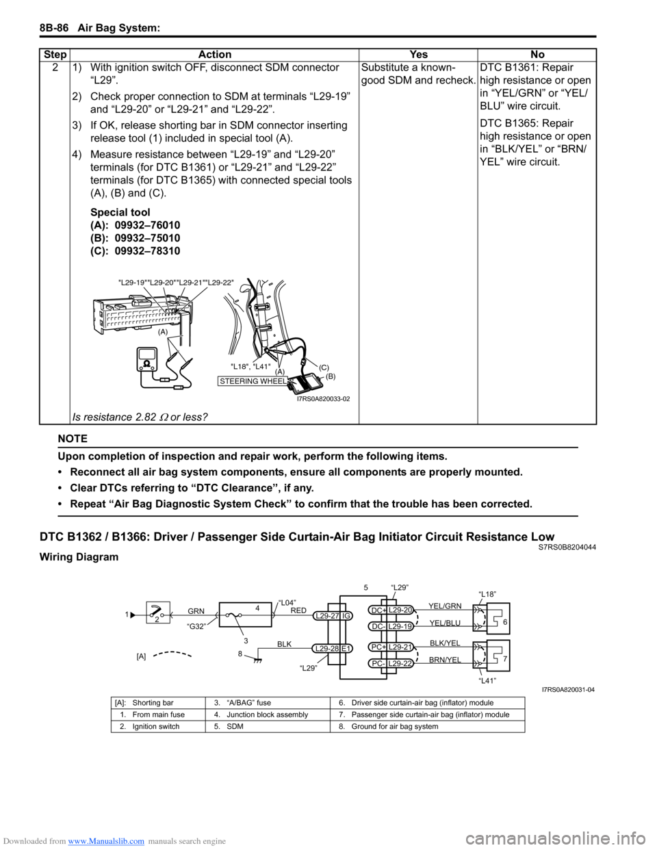
DTC B1362 / B1366: Driver / Passenger Side Curtain-Air Bag Initiator Circuit Resistance LowS7RS0B8204044
Wiring Diagram2 1) With ignition switch OFF, disconnect SDM connector
“L29”.
2) Check proper connection to SDM at terminals “L29-19” and “L29-20” or “L29-21” and “L29-22”.
3) If OK, release shorting bar in SDM connector inserting
release tool (1) included in special tool (A).
4) Measure resistance between “L29-19” and “L29-20” terminals (for DTC B1361) or “L29-21” and “L29-22”
terminals (for DTC B1365) with connected special tools
(A), (B) and (C).
Special tool
(A): 09932–76010
(B): 09932–75010
(C): 09932–78310
Is resistance 2.82
Ω or less? Substitute a known-
good SDM and recheck.
DTC B1361: Repair
high resistance or open
in “YEL/GRN” or “YEL/
BLU” wire circuit.
DTC B1365: Repair
high resistance or open
in “BLK/YEL” or “BRN/
YEL” wire circuit.
Step Action Yes No
(A)
"L29-20""L29-21""L29-22"
"L29-19"
STEERING WHEEL(B)
(C)
(A)
"L18", "L41"
I7RS0A820033-02
1
2
3
GRN
RED
8
BLK
L29-27
L29-28 IG
E1
4
“L29”
“L04”
“G32”
“L29”
L29-20
DC+
L29-19
DC-YEL/BLU
YEL/GRN
56
“L18”
L29-21
PC+
L29-22
PC-BRN/YEL BLK/YEL7
“L41”[A]
I7RS0A820031-04
[A]: Shorting bar 3. “A/BAG” fuse 6. Driver side curtain-air bag (inflator) module
1. From main fuse 4. Junction block assembly 7. Passenger side curtain-air bag (inflator) module
2. Ignition switch 5. SDM 8. Ground for air bag system
Page 1125 of 1496
Downloaded from www.Manualslib.com manuals search engine Air Bag System: 8B-87
CAUTION!
• Be sure to perform “Air Bag Diagnostic System Check” before starting diagnosis according to flow.
• When measurement of resistance or voltage is required in this flow, use a tester along with a correct terminal adapter from special tool (Connector test adapter kit).
• When a check for proper connection is required, refer to “Inspection of Intermittent and Poor Connections”.
• If there is open circuit in the air bag wire harnes s, connector or terminal is found damaged, replace
the wire harness, connector and terminal as an assembly.
DTC Will Set when
The combined resistance of the side curtain-air bag (inflator) module (driver or passenger), harness wiring and
connector terminal contact is below a specified value for specified time.
Flow Test Description
Step 1: Check whether malfunction is in side curtain-air bag (inflator) module.
Step 2: Check side curtain-air bag initiator circuit.
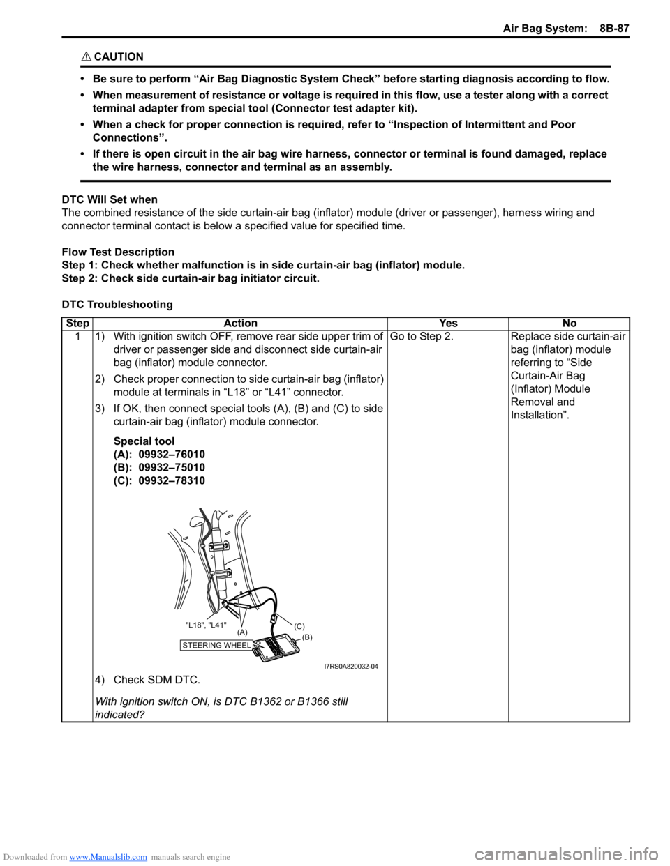
DTC Troubleshooting
Step Action YesNo
1 1) With ignition switch OFF, remove rear side upper trim of driver or passenger side and disconnect side curtain-air
bag (inflator) module connector.
2) Check proper connection to side curtain-air bag (inflator) module at terminals in “L18” or “L41” connector.
3) If OK, then connect special tools (A), (B) and (C) to side curtain-air bag (inflator) module connector.
Special tool
(A): 09932–76010
(B): 09932–75010
(C): 09932–78310
4) Check SDM DTC.
With ignition switch ON, is DTC B1362 or B1366 still
indicated? Go to Step 2.
Replace side curtain-air
bag (inflator) module
referring to “Side
Curtain-Air Bag
(Inflator) Module
Removal and
Installation”.
STEERING WHEEL(B)
(C)
(A)
"L18", "L41"
I7RS0A820032-04
Page 1126 of 1496
Downloaded from www.Manualslib.com manuals search engine 8B-88 Air Bag System:
NOTE
Upon completion of inspection and repair work, perform the following items.
• Reconnect all air bag system components, ensure all components are properly mounted.
• Clear DTCs referring to “DTC Clearance”, if any.
• Repeat “Air Bag Diagnostic System Check” to confirm that the trouble has been corrected.
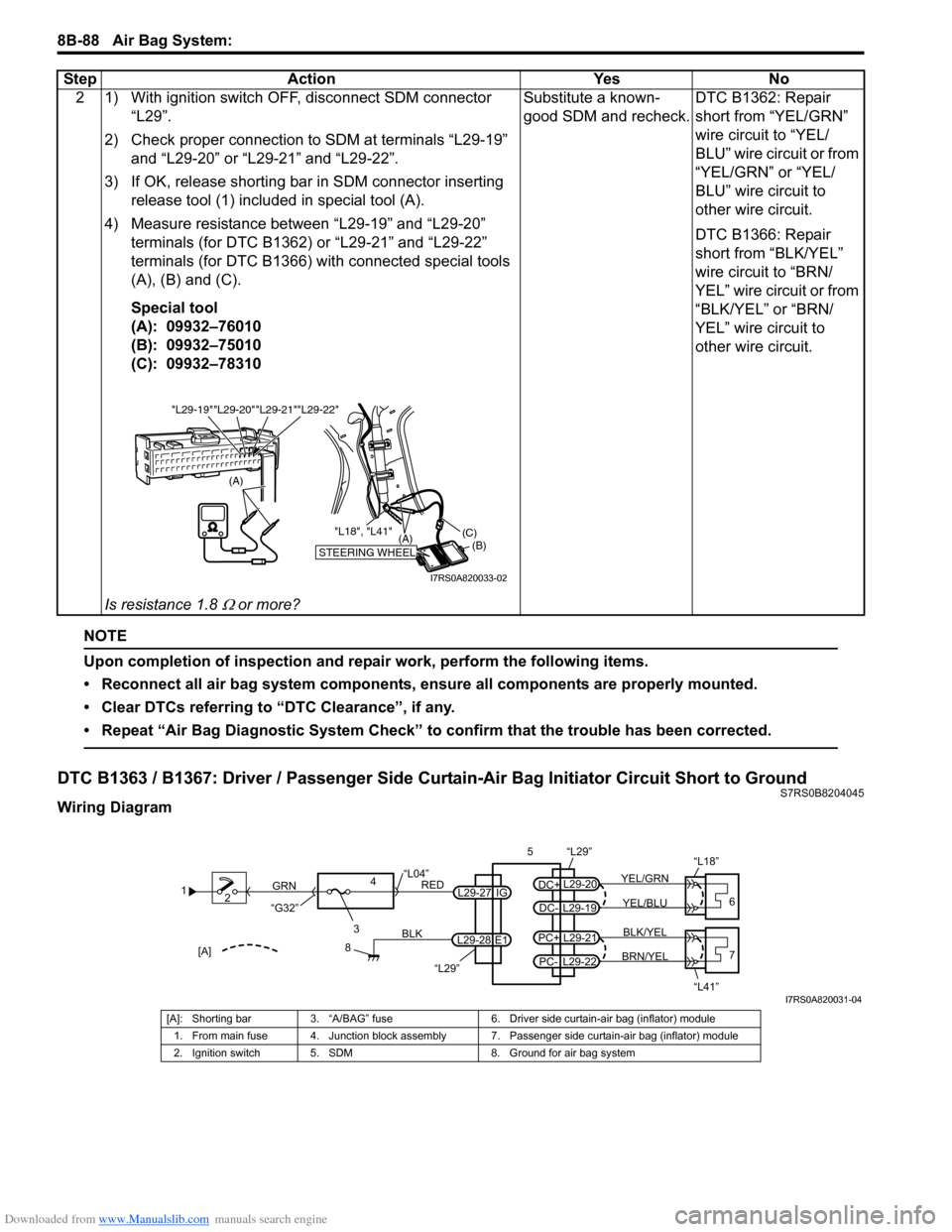
DTC B1363 / B1367: Driver / Passenger Side Curtain-Air Bag Initiator Circuit Short to GroundS7RS0B8204045
Wiring Diagram2 1) With ignition switch OFF, disconnect SDM connector
“L29”.
2) Check proper connection to SDM at terminals “L29-19” and “L29-20” or “L29-21” and “L29-22”.
3) If OK, release shorting bar in SDM connector inserting
release tool (1) included in special tool (A).
4) Measure resistance between “L29-19” and “L29-20” terminals (for DTC B1362) or “L29-21” and “L29-22”
terminals (for DTC B1366) with connected special tools
(A), (B) and (C).
Special tool
(A): 09932–76010
(B): 09932–75010
(C): 09932–78310
Is resistance 1.8
Ω or more? Substitute a known-
good SDM and recheck.
DTC B1362: Repair
short from “YEL/GRN”
wire circuit to “YEL/
BLU” wire circuit or from
“YEL/GRN” or “YEL/
BLU” wire circuit to
other wire circuit.
DTC B1366: Repair
short from “BLK/YEL”
wire circuit to “BRN/
YEL” wire circuit or from
“BLK/YEL” or “BRN/
YEL” wire circuit to
other wire circuit.
Step Action Yes No
(A)
"L29-20""L29-21""L29-22"
"L29-19"
STEERING WHEEL(B)
(C)
(A)
"L18", "L41"
I7RS0A820033-02
1
2
3
GRN
RED
8
BLK
L29-27
L29-28 IG
E1
4
“L29”
“L04”
“G32”
“L29”
L29-20
DC+
L29-19
DC-YEL/BLU
YEL/GRN
56
“L18”
L29-21
PC+
L29-22
PC-BRN/YEL BLK/YEL7
“L41”[A]
I7RS0A820031-04
[A]: Shorting bar 3. “A/BAG” fuse 6. Driver side curtain-air bag (inflator) module
1. From main fuse 4. Junction block assembly 7. Passenger side curtain-air bag (inflator) module
2. Ignition switch 5. SDM 8. Ground for air bag system
Page 1128 of 1496
Downloaded from www.Manualslib.com manuals search engine 8B-90 Air Bag System:
NOTE
Upon completion of inspection and repair work, perform the following items.
• Reconnect all air bag system components, ensure all components are properly mounted.
• Clear DTCs referring to “DTC Clearance”, if any.
• Repeat “Air Bag Diagnostic System Check” to confirm that the trouble has been corrected.
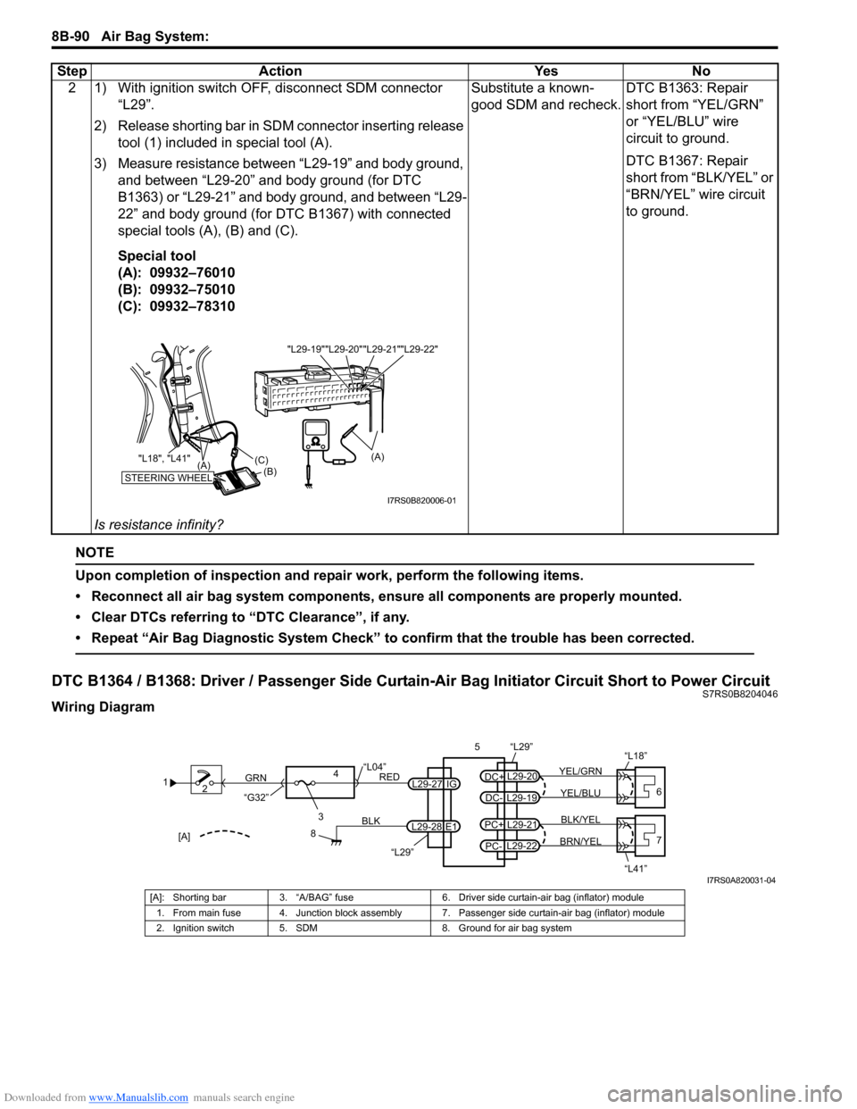
DTC B1364 / B1368: Driver / Passenger Side Curtain-Air Bag Initiator Circuit Short to Power CircuitS7RS0B8204046
Wiring Diagram2 1) With ignition switch OFF, disconnect SDM connector
“L29”.
2) Release shorting bar in SDM connector inserting release tool (1) included in special tool (A).
3) Measure resistance between “L29-19” and body ground, and between “L29-20” and body ground (for DTC
B1363) or “L29-21” and body ground, and between “L29-
22” and body ground (for DTC B1367) with connected
special tools (A), (B) and (C).
Special tool
(A): 09932–76010
(B): 09932–75010
(C): 09932–78310
Is resistance infinity? Substitute a known-
good SDM and recheck.
DTC B1363: Repair
short from “YEL/GRN”
or “YEL/BLU” wire
circuit to ground.
DTC B1367: Repair
short from “BLK/YEL” or
“BRN/YEL” wire circuit
to ground.
Step Action Yes No
"L29-20""L29-21""L29-22"
"L29-19"
STEERING WHEEL(B)
(C)
(A)
"L18", "L41"
(A)
I7RS0B820006-01
1
2
3
GRN
RED
8
BLK
L29-27
L29-28 IG
E1
4
“L29”
“L04”
“G32”
“L29”
L29-20
DC+
L29-19
DC-YEL/BLU
YEL/GRN
56
“L18”
L29-21
PC+
L29-22
PC-BRN/YEL BLK/YEL7
“L41”[A]
I7RS0A820031-04
[A]: Shorting bar 3. “A/BAG” fuse 6. Driver side curtain-air bag (inflator) module
1. From main fuse 4. Junction block assembly 7. Passenger side curtain-air bag (inflator) module
2. Ignition switch 5. SDM 8. Ground for air bag system
Page 1133 of 1496
Downloaded from www.Manualslib.com manuals search engine Air Bag System: 8B-95
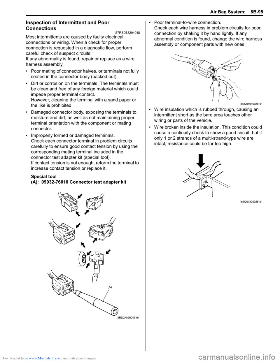
Inspection of Intermittent and Poor
Connections
S7RS0B8204048
Most intermittents are caused by faulty electrical
connections or wiring. When a check for proper
connection is requested in a diagnostic flow, perform
careful check of suspect circuits.
If any abnormality is found, repair or replace as a wire
harness assembly.
• Poor mating of connector halves, or terminals not fully seated in the connector body (backed out).
• Dirt or corrosion on the terminals. The terminals must be clean and free of any foreign material which could
impede proper terminal contact.
However, cleaning the terminal with a sand paper or
the like is prohibited.
• Damaged connector body, exposing the terminals to moisture and dirt, as well as not maintaining proper
terminal orientation with the component or mating
connector.
• Improperly formed or damaged terminals. Check each connector terminal in problem circuits
carefully to ensure good contact tension by using the
corresponding mating terminal included in the
connector test adapter kit (special tool).
If contact tension is not e nough, reform the terminal to
increase contact tension or replace it.
Special tool
(A): 09932-76010 Connector test adapter kit • Poor terminal-to-wire connection.
Check each wire harness in problem circuits for poor
connection by shaking it by hand lightly. If any
abnormal condition is found, change the wire harness
assembly or component parts with new ones.
• Wire insulation which is rubbed through, causing an intermittent short as the bare area touches other
wiring or parts of the vehicle.
• Wire broken inside the insulation. This condition could cause a continuity check to show a good circuit, but if
only 1 or 2 strands of a multi-strand-type wire are
intact, resistance could be far too high.
(A)
I4RS0A820045-01
IYSQ01010028-01
IYSQ01820025-01
Page 1163 of 1496
Downloaded from www.Manualslib.com manuals search engine Air Bag System: 8B-125
Specifications
Tightening Torque SpecificationsS7RS0B8207001
NOTE
The specified tightening torque is also described in the following.
“Air Bag System Components, Wiring and Connectors Location”
Reference:
For the tightening torque of fastener not specified in this section, refer to “Fasteners Information in Section 0A”.
Special Tools and Equipment
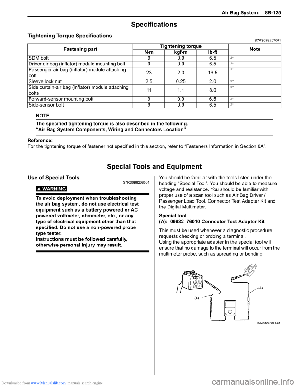
Use of Special ToolsS7RS0B8208001
WARNING!
To avoid deployment when troubleshooting
the air bag system, do not use electrical test
equipment such as a battery powered or AC
powered voltmeter, ohmmeter, etc., or any
type of electrical equipment other than that
specified. Do not use a non-powered probe
type tester.
Instructions must be followed carefully,
otherwise personal injury may result.
You should be familiar with the tools listed under the
heading “Special Tool”. You should be able to measure
voltage and resistance. You should be familiar with
proper use of a scan tool such as Air Bag Driver /
Passenger Load Tool, Connector Test Adapter Kit and
the Digital Multimeter.
Special tool
(A): 09932–76010 Connector Test Adapter Kit
This must be used whenever a diagnostic procedure
requests checking or probing a terminal.
Using the appropriate adapter in the special tool will
ensure that no damage to the terminal will occur from the
multimeter probe, such as spreading or bending.
Fastening part
Tightening torque
Note
N ⋅mkgf-mlb-ft
SDM bolt 9 0.9 6.5 �)
Driver air bag (inflator) module mounting bolt 9 0.9 6.5 �)
Passenger air bag (inflator) module attaching
bolt 23 2.3 16.5�)
Sleeve lock nut 2.5 0.25 2.0 �)
Side curtain-air bag (inflator) module attaching
bolts 11 1.1 8.0�)
Forward-sensor mounting bolt 9 0.9 6.5 �)
Side-sensor bolt 9 0.9 6.5 �)
I3JA01820041-01