Page 1172 of 1496

Downloaded from www.Manualslib.com manuals search engine 9A-1 Wiring Systems:
Body, Cab and Accessories
Wiring Systems
Precautions
Cautions in Body Electrical System ServicingS7RS0B9100001
When servicing the electric systems, observe the cautions described in “Precautions for Electrical Circuit Service in
Section 00” to protect electrical parts and to prevent a fire.
General Description
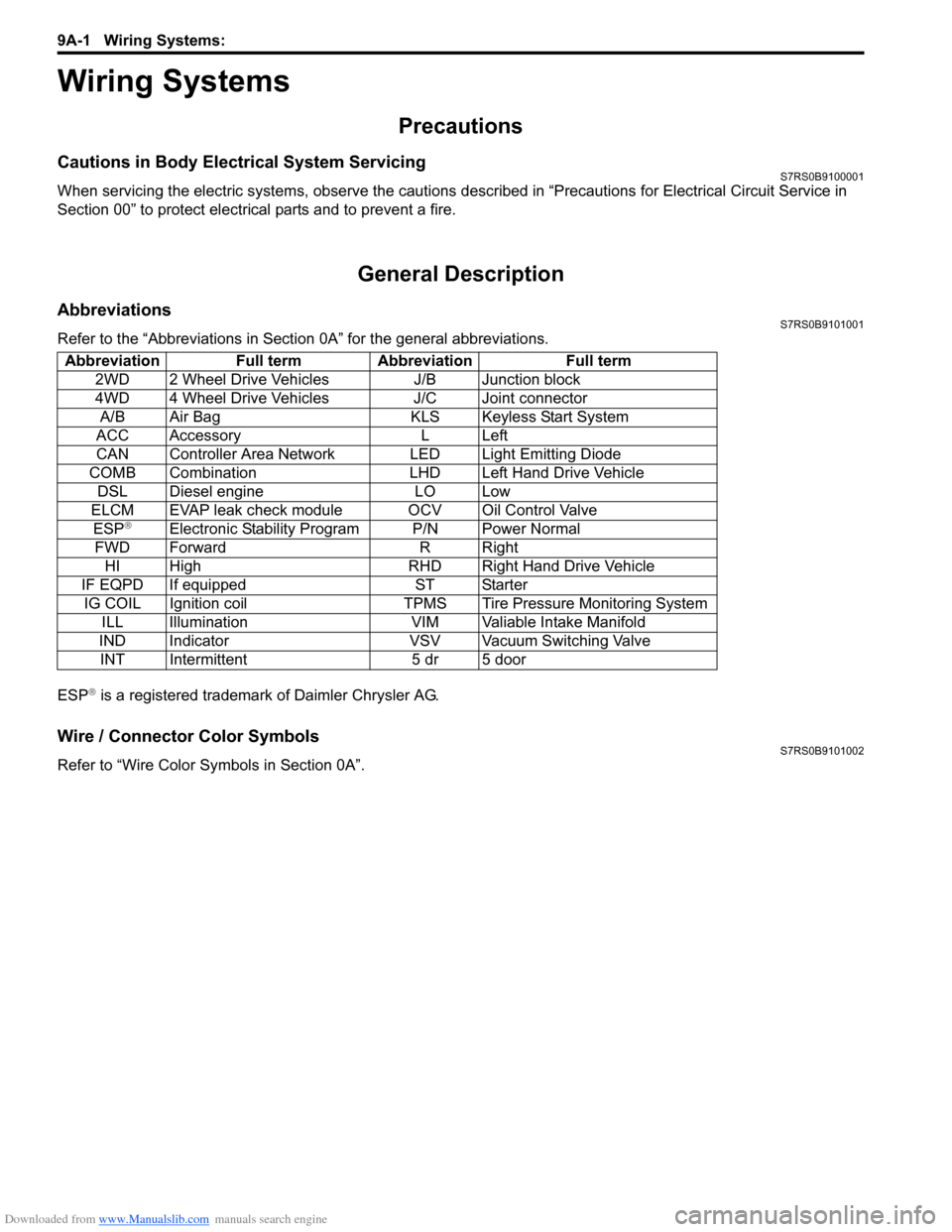
AbbreviationsS7RS0B9101001
Refer to the “Abbreviations in Sect ion 0A” for the general abbreviations.
ESP
® is a registered trademark of Daimler Chrysler AG.
Wire / Connector Color SymbolsS7RS0B9101002
Refer to “Wire Color Sy mbols in Section 0A”.
Abbreviation Full term Abbreviation Full term
2WD 2 Wheel Drive Vehicles J/B Junction block
4WD 4 Wheel Drive Vehicles J/C Joint connectorA/B Air Bag KLS Keyless Start System
ACC Accessory L Left
CAN Controller Area Network LED Light Emitting Diode
COMB Combination LHD Left Hand Drive Vehicle DSL Diesel engine LO Low
ELCM EVAP leak check module OCV Oil Control Valve ESP
®Electronic Stability Program P/N Power Normal
FWD Forward R Right HI High RHD Right Hand Drive Vehicle
IF EQPD If equipped ST Starter IG COIL Ignition coil TPMS Tire Pressure Monitoring System ILL Illumination VIM Valiable Intake Manifold
IND Indicator VSV Vacuum Switching Valve INT Intermittent 5 dr 5 door
Page 1173 of 1496

Downloaded from www.Manualslib.com manuals search engine Wiring Systems: 9A-2
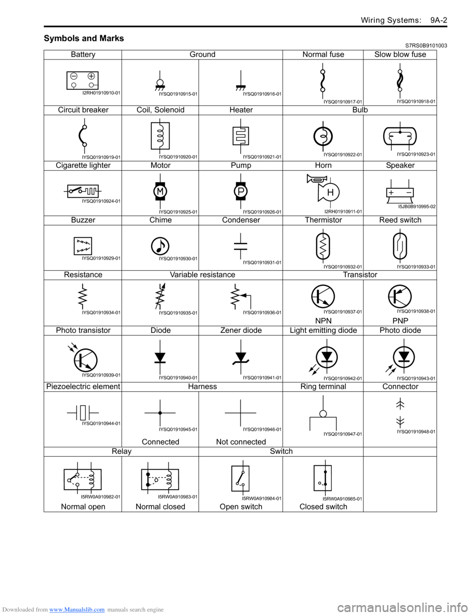
Symbols and MarksS7RS0B9101003
BatteryGroundNormal fuse Slow blow fuse
Circuit breaker Coil, SolenoidHeater Bulb
Cigarette lighter MotorPump HornSpeaker
Buzzer ChimeCondenser Thermistor Reed switch
Resistance Variable resistance Transistor
NPN PNP
Photo transistor DiodeZener diode L ight emitting diode Photo diode
Piezoelectric element Harness Ring terminal Connector
Connected Not connected
Relay Switch
Normal open Normal closed Open switch Closed switch
I2RH01910910-01IYSQ01910915-01IYSQ01910916-01
IYSQ01910917-01IYSQ01910918-01
IYSQ01910919-01IYSQ01910920-01IYSQ01910921-01IYSQ01910922-01IYSQ01910923-01
IYSQ01910924-01
IYSQ01910925-01IYSQ01910926-01
H
I2RH01910911-01I5JB0B910995-02
IYSQ01910929-01IYSQ01910930-01IYSQ01910931-01IYSQ01910932-01IYSQ01910933-01
IYSQ01910934-01IYSQ01910935-01IYSQ01910936-01IYSQ01910937-01IYSQ01910938-01
IYSQ01910939-01IYSQ01910940-01IYSQ01910941-01IYSQ01910942-01IYSQ01910943-01
IYSQ01910944-01IYSQ01910945-01IYSQ01910946-01IYSQ01910947-01IYSQ01910948-01
I5RW0A910982-01I5RW0A910983-01I5RW0A910984-01I5RW0A910985-01
Page 1177 of 1496

Downloaded from www.Manualslib.com manuals search engine Wiring Systems: 9A-6
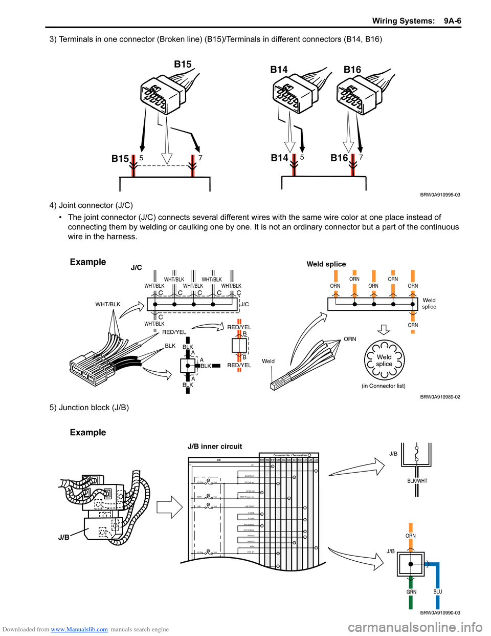
3) Terminals in one connector (Broken line) (B15)/Terminals in different connectors (B14, B16)
4) Joint connector (J/C)• The joint connector (J/C) connects several different wires with the same wire color at one place instead of
connecting them by welding or caulking one by one. It is not an ordinary connector but a part of the continuous
wire in the harness.
5) Junction block (J/B)
B15 B15
B14 B1657B14 B1657
I5RW0A910995-03
BLKBLK
A
A
A B
B
RED/YEL
WeldORN
WHT/BLK
J/C
Weld splice
BLKBLK
RED/YEL
RED/YEL
WHT/BLK
WHT/BLK
WHT/BLKWHT/BLKWHT/BLKWHT/BLKC
CCCCCWeld
splice
(in Connector list)
J/C
ORNORNORNORNORN
ORN
Weld
splice
Example
I5RW0A910989-02
IMMOBI IG IG1IG Coil, etc E39 E41E40
BCM G34
G33
G32 K01 L04 L05 L06
IG Coil
IG1
15A
MTR10A
A/B15A
2
65
13
J/B Connector No. / Terminal No.
BCM ;IG1
MTR Power, etc
A/B CONTK-LINE K-LINE
A/B SIGNAL
A/B SIGNAL
A/B SIG
A/B SIG
IG Sig 10AEPS ATMTA
4
6
1
3
24
8
11
9
12
9
11
23
25
30
29
Example
J/B
J/B
ORN
GRNBLU
J/B
J/B inner circuit
BLK/WHT
I5RW0A910990-03
Page 1178 of 1496
Downloaded from www.Manualslib.com manuals search engine 9A-7 Wiring Systems:
6) Connector location, shape and terminal No.Refer to “Connector Layout Diagram”.
Refer to “System Circuit Diagram”.
Refer to “List of Connectors”.
How to Read Ground PointS7RS0B9101006
Refer to “System Circuit Diagram”.
Refer to “Ground (earth) Point”.
"SYSTEM CIRCUIT DIAGRAM"
-Connector code and terminal No.
"CONNECTOR LAYOUT DIAGRAM"
-Connector location.
CROSS-REFERENCE
"CONNECTOR LIST"
-Connector shape and terminal position.
C02
C02 C02
C02
C02
C02
I5RW0A910991-02
Left side shown
101112
"SYSTEM CIRCUIT DIAGRAM"
"GROUND POINT"
CROSS-REFERENCE
Windoshield
washer
motor Individual
circuit
fuse box
2015A
Windoshield
wiper
motor
E40
E09
E20
16
2
1
Off
On
Circuit
breaker
60A-B003-
YEL/BLU
1
205
2
134
67
BLU/BLK
BLK
10
BLK
BLK
9
10
10
BLK
M
BLUBLU/WHTBLU/RED
M
Device body grounding is not given the ground point number.
I5RW0A910992-02
Page 1179 of 1496

Downloaded from www.Manualslib.com manuals search engine Wiring Systems: 9A-8
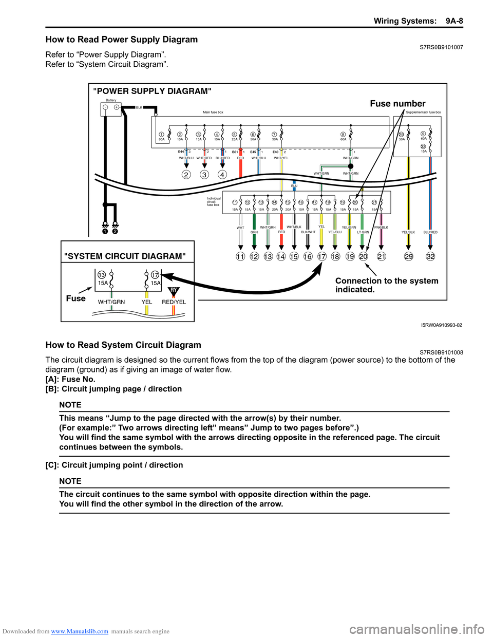
How to Read Power Supply DiagramS7RS0B9101007
Refer to “Power Supply Diagram”.
Refer to “System Circuit Diagram”.
How to Read System Circuit DiagramS7RS0B9101008
The circuit diagram is designed so the current flows from the top of the diagram (power source) to the bottom of the
diagram (ground) as if giving an image of water flow.
[A]: Fuse No.
[B]: Circuit jumping page / direction
NOTE
This means “Jump to the page directed with the arrow(s) by their number.
(For example:” Two arrows directing left” means” Jump to two pages before”.)
You will find the same symbol with the arrows directing opposite in the referenced page. The circuit
continues between the symbols.
[C]: Circuit jumping point / direction
NOTE
The circuit continues to the same symbol with opposite direction within the page.
You will find the other symbol in the direction of the arrow.
Connection to the system
indicated.
"POWER SUPPLY DIAGRAM"
-+
1
Battery
80A
215A315A415A525A67850A 30A2930A3215A
960A
60A
BLK
YEL/BLKPNK/BLKLT GRNYEL/GRNYEL/BLUBLK/WHTWHT/BLKWHT/GRNREDGRNWHT
WHT/BLUWHT/REDWHT/BLUWHT/YELWHT/GRN
WHT/GRNWHT/GRN
BLU
BLU/REDRED
YELBLU/RED
Individual
circuit
fuse box
Main fuse box
Supplementary fuse box
11
11
243
121314151617181920212932
1213141516171819202115A 15A 15A 20A 20A 15A 15A 15A 15A 15A 15A
E44
321
B011E45 1 E4021
FuseRED/YEL
YEL
WHT/GRN
15A
15A
1317
"SYSTEM CIRCUIT DIAGRAM"
Fuse number
1
2
RY
I5RW0A910993-02
Page 1202 of 1496
Downloaded from www.Manualslib.com manuals search engine 9A-31 Wiring Systems:
Power Supply Diagram
Power Supply DiagramS7RS0B910D001
Refer to “Fuses and the Protected Parts”.
Refer to “Fuses in Main Fuse Box (RHD)”.
Refer to “Individual Circuit Fuse Box No. 1”.
Refer to “Individual Circuit Fuse Box No. 2 (In J/B)”.
Refer to “Junction Block (J/B) Connector / Fuse Layout”.
Refer to “Junction Block Inner Circuit (Overview)”.
Refer to “Junction Block Inner Circuit (Detail)”.
Page 1203 of 1496
Downloaded from www.Manualslib.com manuals search engine Wiring Systems: 9A-32
G32
J/B
3
WHT/BLU
4G213
12
10
BLK
21
BLK/GRY
10A
15A30A
5647891012
E27
WHT
131416192021
BLUBLU/YEL
6
BLK/YEL
5
YEL/BLU
7
PNK
89
WHT/RED
RED
GRN
12
WHT
GRY
14
WHT/GRN
19
WHT/BLU
2021
WHT/REDWHT/BLU
16
15A
15A 30A 50A
30A
30A 30A
30A
15A15A
15A
BLK
2E261
WHT/BLU
C31 C331 1
WHT
BLK
Main fuse box
Starting motor "A-1"
Generator
"A-2"
Battery
80A
50A
50A
3
80A
47
80A
46
2
1
E401WHT
"Junction Block
Inner circuit"
J/B (E40- )
YEL
"Junction BlockInner circuit"
J/B (G32- )
2
1
"Junction BlockInner circuit"
J/B (E39- ) 7
J/B (G32- ) 4
GRN/WHT
Individual circuit fuse box
+B1
LOCK
ACC
ON
ST ACC IG1 IG2
STOUT
IN
+B2
6
GRN
J/B (G32- )
2
5BLU
J/B (G32- )5
IF EQPD
18
YEL/BLU
18
15A
M16A engine
W
B
RHD
LHDAB
A
A
B1 2AB21
B
I6RS0C910907-01
Page 1204 of 1496
Downloaded from www.Manualslib.com manuals search engine 9A-33 Wiring Systems:
Fuses and the Protected PartsS7RS0B910D002
The chart below describes what parts each fuse protects.
Fuses in Main Fuse Box (RHD)S7RS0B910D003
Fuses in Main Fuse Box (LHD)S7RS0B910D004
No.Fuse Protected circuit
80 A All electric circuit
Battery
Generator
50 A LAMP
50 A IG switch
Supplementary fuse box No.2 (In J/B)
80 A Individual circuit fuse box
80 A Individual circuit fuse box
1
3
2
I4RS0A910905-01
2
3
47
46
1
I4RS0B910974-01