2007 SUZUKI SWIFT engine temperature
[x] Cancel search: engine temperaturePage 1312 of 1496
Downloaded from www.Manualslib.com manuals search engine 9C-17 Instrumentation / Driver Info. / Horn:
Door Switch (Front / Rear Door) InspectionS7RS0B9306011
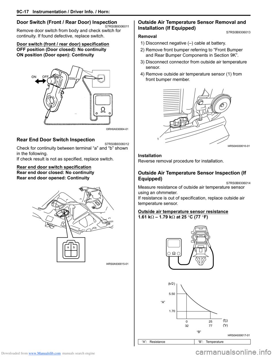
Remove door switch from body and check switch for
continuity. If found defective, replace switch.
Door switch (front / rear door) specification
OFF position (Door closed): No continuity
ON position (Door open): Continuity
Rear End Door Switch InspectionS7RS0B9306012
Check for continuity between terminal “a” and “b” shown
in the following.
If check result is not as specified, replace switch.
Rear end door switch specification
Rear end door closed: No continuity
Rear end door opened: Continuity
Outside Air Temperature Sensor Removal and
Installation (If Equipped)
S7RS0B9306013
Removal
1) Disconnect negative (–) cable at battery.
2) Remove front bumper referring to “Front Bumper and Rear Bumper Components in Section 9K”.
3) Disconnect connector from outside air temperature sensor.
4) Remove outside air temperature sensor (1) from front bumper member.
Installation
Reverse removal procedure for installation.
Outside Air Temperature Sensor Inspection (If
Equipped)
S7RS0B9306014
Measure resistance of outside air temperature sensor
using an ohmmeter.
If resistance is out of specif ication, replace outside air
temperature sensor.
Outside air temperature sensor resistance
1.61 kΩ – 1.79 k Ω at 25 °C (77 °F)
I3RH0A930004-01
a
b
I4RS0A930015-01
“A”: Resistance “B”: Temperature
1
I4RS0A930016-01
“B”
“A”
5.50
1.70 0
32 25
77
F
I4RS0A930017-01
Page 1389 of 1496
Downloaded from www.Manualslib.com manuals search engine Paint / Coatings: 9L-2
Plastic Parts FinishingS7RS0B9C01002
Paintable plastic parts are ABS plastic parts.
Painting
Rigid or hand ABS plastic needs no primer coating.
General acrylic lacquers can be painted properly over hard ABS plastic in terms of adherence.
1) Use cleaning solvent for paint finish to wash each part.
2) Apply conventional acrylic color lacquer to part surface.
3) Follow lacquer directions for required drying time. (Proper drying temperature range is 60 – 70 °C (140 – 158 ° F)).
Reference
Plastic parts employ not only ABS (Acrylonitrile Butadiene Styrene) plastic but also polypro pylene, vinyl, or the like
plastic. Burning test method to iden tify ABS plastic is described below.
1) Use a sharp blade to cut off a plastic sliver from the part at its hidden backside.
2) Hold sliver with pincer s and set it on fire.
3) Carefully observe condition of the burning plastic.
4) ABS plastic must raise readily dist inguishable back smoke while burning with its residue suspended in air
temporarily.
5) Polypropylene must raise no readily distinguishable smoke while burning.
Page 1401 of 1496
Downloaded from www.Manualslib.com manuals search engine Table of Contents 10- i
10
Section 10
CONTENTS
Control Systems
Precautions ............................................... 10-1
Precautions........................................................... 10-1
Precautions for Control Systems......................... 10-1
Body Electrical Contro l System ........... 10B-1
Precautions......................................................... 10B-1
Precautions in Diagnosing Trouble ................... 10B-1
General Description ........................................... 10B-1 BCM General Description ................................. 10B-1
CAN Communication System Description......... 10B-2
Theft Deterrent Light ......................................... 10B-3
Security Alarm Description (If Equipped) .......... 10B-3
Schematic and Routing Diagram ...................... 10B-4 Body Electrical Control System Wiring Circuit Diagram .......................................................... 10B-4
Connector Layout Diagram of BCM and Junction Block Assembly ................................ 10B-7
Component Locatio n ......................................... 10B-8
BCM and Related System Component Location .......................................................... 10B-8
Diagnostic Information an d Procedures .......... 10B-9
BCM Self-Diagnosis Function ........................... 10B-9
Body Electrical Control System Check............ 10B-10
Scan Tool Data ............................................... 10B-12
DTC Table ....................................................... 10B-14
DTC Check ..................................................... 10B-14
DTC Clearance ............................................... 10B-15
BCM Power Circuit and Ground Circuit Check 10B-16
DTC B1133 (DTC No. 1133): Battery Voltage Too High ....................................................... 10B-17
DTC B1141 / DTC B1142 (No. 1141 / No. 1142): Outside Air Temperature (Ambient
Temp.) Sensor Circuit Ma lfunction ................ 10B-18
DTC B1150 (No. 1150): Air Bag Communication Circuit Malfunction .............. 10B-19
DTC B1157 (No. 1157): Air Bag Deployment Signal Input ................................................... 10B-20
DTC B1170 (No. 1170 ): EEPROM Access
Error .............................................................. 10B-21
DTC U0155 (No. 0155): Lost Communication with Instrument Panel Cluster (IPC) Control
Module .......................................................... 10B-21
DTC U1073 (No. 1073): Control Module Communication Bus Off ................................ 10B-24 DTC U1100 (No. 1100): Lost Communication
with ECM ....................................................... 10B-25
DTC U1101 (No. 1101): Lost Communication with TCM ....................................................... 10B-27
DTC U1144 (No. 1144): Lost Communication with Keyless Start Control Module ................ 10B-29
Inspection of BCM and its Circuits .................. 10B-31
Repair Instructions ........... ...............................10B-39
BCM (Included in Junction Block Assembly) Removal and Installation ............................... 10B-39
Outside Air Temperature Sensor Removal and Installation .............................................. 10B-39
Outside Air Temperature Sensor Inspection ... 10B-39
Security Alarm Mode Selection Procedure (If Equipped) ...................................................... 10B-39
Special Tools and Equipmen t .........................10B-40
Special Tool .................................................... 10B-40
Immobilizer Control Syst em ................. 10C-1
Precautions.........................................................10C-1
Precautions in Diagnosing Troubles .................10C-1
Precaution in Replacing ECM ...........................10C-1
Precautions in Handli ng Immobilizer Control
System ............................................................10C-1
General Description ...........................................10C-2 Immobilizer Control System Introduction ..........10C-2
Immobilizer Control System Components Location...........................................................10C-3
On-Board Diagnostic System Description (Self-diagnosis Function) ................................10C-3
Schematic and Routing Diag ram ......................10C-4
Immobilizer Control System Wiring Circuit Diagram...........................................................10C-4
Diagnostic Information an d Procedures ..........10C-5
Immobilizer Control System Check ...................10C-5
Diagnostic Trouble Code (DTC) Check.............10C-5
Diagnostic Trouble Code (DTC) Clearance ......10C-6
Diagnostic Trouble Code (DTC) Table ..............10C-6
Scan Tool Data .................................................10C-7
Immobilizer Indicator Lamp Does Not Come ON with Ignition Switch ON and Engine Stop ..10C-7
Immobilizer Indicator Lamp Remains ON after Engine Starts...................................................10C-8
DTC P1614: Transponder Re sponse Error .......10C-9
Page 1405 of 1496
Downloaded from www.Manualslib.com manuals search engine Body Electrical Control System: 10B-2
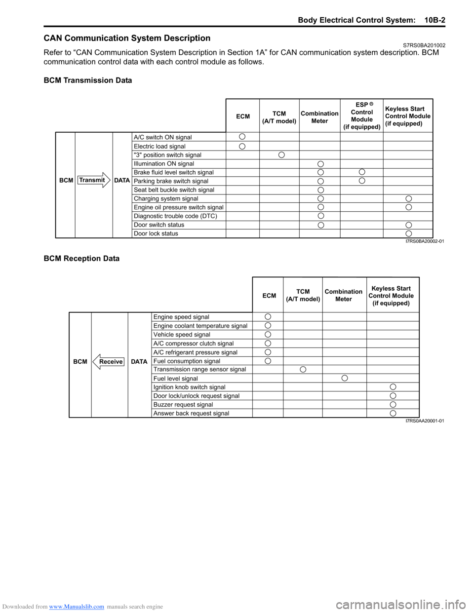
CAN Communication System DescriptionS7RS0BA201002
Refer to “CAN Communication System Description in Section 1A” for CAN communication system description. BCM
communication control data with ea ch control module as follows.
BCM Transmission Data
BCM Reception Data
A/C switch ON signal
Electric load signal
"3" position switch signal
Illumination ON signal
Brake fluid level switch signal
Parking brake switch signal
Seat belt buckle switch signal
Charging system signal
Engine oil pressure switch signal
Diagnostic trouble code (DTC)
Door switch status
Door lock status ECM
TCM
(A/T model) Combination
Meter Keyless Start
Control Module
(if equipped)
Transmit DATA
BCM
ESP
Control Module
(if equipped)
I7RS0BA20002-01
Engine speed signal
Vehicle speed signal Engine coolant temperature signal
A/C refrigerant pressure signal
Fuel consumption signal A/C compressor clutch signal
Transmission range sensor signal
Fuel level signal
Ignition knob switch signal
Door lock/unlock request signal
Buzzer request signal
Answer back request signal
DATA
BCM
Receive
Combination
Meter
TCM
(A/T model) Keyless Start
Control Module (if equipped)
ECM
I7RS0AA20001-01
Page 1409 of 1496
![SUZUKI SWIFT 2007 2.G Service Workshop Manual Downloaded from www.Manualslib.com manuals search engine Body Electrical Control System: 10B-6
[A]: Vehicle not equipped with diagnosis connector 19. Door key cylinder switch (included in door lock a SUZUKI SWIFT 2007 2.G Service Workshop Manual Downloaded from www.Manualslib.com manuals search engine Body Electrical Control System: 10B-6
[A]: Vehicle not equipped with diagnosis connector 19. Door key cylinder switch (included in door lock a](/manual-img/20/7607/w960_7607-1408.png)
Downloaded from www.Manualslib.com manuals search engine Body Electrical Control System: 10B-6
[A]: Vehicle not equipped with diagnosis connector 19. Door key cylinder switch (included in door lock actuator)40. SDM
[B]: Vehicle equipped with diagnosis conn ector 20. Manual door lock switch 41. Rear end door window defogger relay
[C]: ESP ® model 21. Rear end door window defogger switch 42. Rear end door window defogger
1. BCM (included in junction block assembly) 22. Rear end door opener switch 43. Rear end door window defogger indicator lamp
2. Rear washer motor 23. “3” position switch (A/T model)44. Horn relay
3. Rear wiper motor 24. A/C switch45. Horn switch
4. Rear wiper relay 25. Rear end door opener relay46. Horn
5. Rear wiper and washer switch 26. Rear end door opener actuator47. Lighting switch
6. Outside air temperature sensor 27. TCM (A/T model)48. Ignition switch
7. Key reminder switch 28. ECM49. Battery
8. Theft deterrent light 29. Combination meter50. To turn signal light
9. Oil pressure switch 30. Data link connector (DLC)51. Body ground
10. Generator 31. To ECM, ABS/ESP®, P/S control module 52. Engine ground
11. Information display (if equipped) 32. To SDM53. Keyless start control module (if equipped)
12. Keyless entry receiver (if equipped) 33. Door lock actuator relay 54. Right side door mirror heater (if equipped)
13. Driver side door switch 34. Driver side door lock actuator55. Left side door mirror heater (if equipped)
14. Other than driver side door switch 35. Passenger side door lock actuator56. ABS/ESP® control module
15. Rear end door switch 36. Rear door lock actuator57. To HVAC control module
16. Driver side seat belt switch 37. Turn signal and hazard warning relay 58. CAN junction connector
17. Brake fluid level switch 38. Hazard warning switch59. Steering angle sensor
18. Parking brake switch 39. Interior light
Page 1412 of 1496
Downloaded from www.Manualslib.com manuals search engine 10B-9 Body Electrical Control System:
Diagnostic Information and Procedures
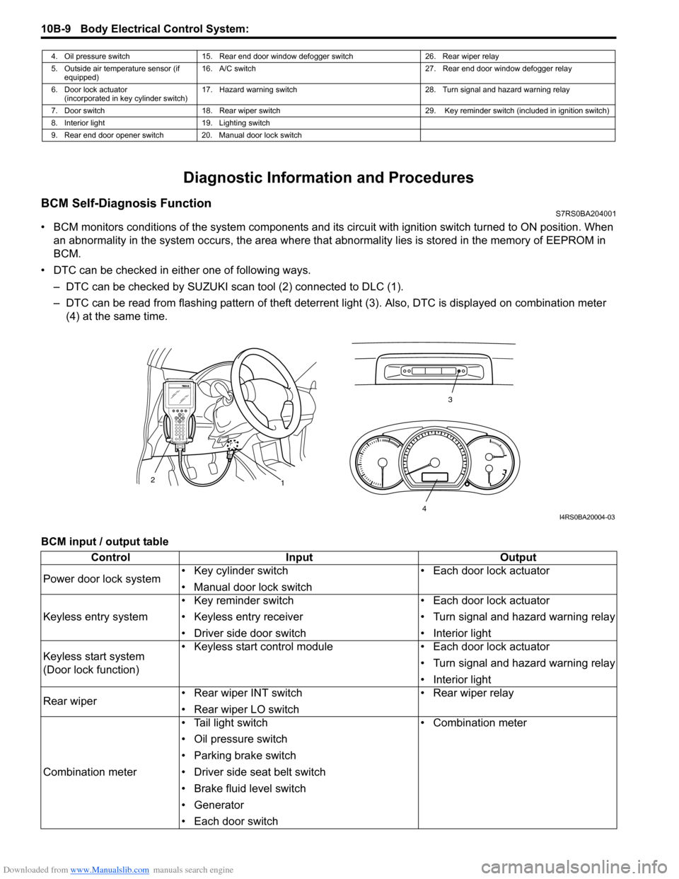
BCM Self-Diagnosis FunctionS7RS0BA204001
• BCM monitors conditions of the system components and its circuit with ignition switch turned to ON position. When
an abnormality in the system oc curs, the area where that abnormality lies is stored in the memory of EEPROM in
BCM.
• DTC can be checked in either one of following ways. – DTC can be checked by SUZUKI scan tool (2) connected to DLC (1).
– DTC can be read from flashing pattern of theft deterrent light (3). Also, DTC is displayed on combination meter
(4) at the same time.
BCM input / output table
4. Oil pressure switch 15. Rear end door window defogger switch 26. Rear wiper relay
5. Outside air temperature sensor (if equipped) 16. A/C switch
27. Rear end door window defogger relay
6. Door lock actuator (incorporated in key cylinder switch) 17. Hazard warning switch
28. Turn signal and hazard warning relay
7. Door switch 18. Rear wiper switch 29. Key reminder switch (included in ignition switch)
8. Interior light 19. Lighting switch
9. Rear end door opener switch 20. Manual door lock switch
3
1
2
4I4RS0BA20004-03
Control
Input Output
Power door lock system • Key cylinder switch
• Manual door lock switch • Each door lock actuator
Keyless entry system • Key reminder switch
• Keyless entry receiver
• Driver side door switch • Each door lock actuator
• Turn signal and hazard warning relay
• Interior light
Keyless start system
(Door lock function) • Keyless start control module
• Each door lock actuator
• Turn signal and hazard warning relay
• Interior light
Rear wiper • Rear wiper INT switch
• Rear wiper LO switch • Rear wiper relay
Combination meter • Tail light switch
• Oil pressure switch
• Parking brake switch
• Driver side seat belt switch
• Brake fluid level switch
• Generator
• Each door switch • Combination meter
Page 1414 of 1496
Downloaded from www.Manualslib.com manuals search engine 10B-11 Body Electrical Control System:
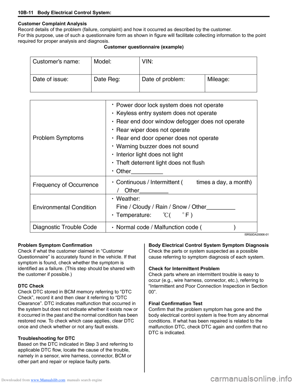
Customer Complaint Analysis
Record details of the problem (failure, complaint) and how it occurred as described by the customer.
For this purpose, use of such a questionnaire form as shown in figure will facilitate collectin g information to the point
required for proper analysis and diagnosis. Customer questionnaire (example)
Problem Symptom Confirmation
Check if what the custom er claimed in “Customer
Questionnaire” is accurately f ound in the vehicle. If that
symptom is found, check whether the symptom is
identified as a failure. (This step should be shared with
the customer if possible.)
DTC Check
Check DTC stored in BCM me mory referring to “DTC
Check”, record it and then clear it referring to “DTC
Clearance”. DTC indicates malfunction that occurred in
the system but does not indicate whether it exists now or
it occurred in the past and the normal condition has been
restored now. To check which case applies, clear DTC
once and check whether or not any fault exists.
Troubleshooting for DTC
Based on the DTC indicated in Step 3 and referring to
applicable DTC flow, locate the cause of the trouble,
namely in a sensor, wire harness, connector, BCM or
other part and repair or replace faulty parts. Body Electrical Control System Symptom Diagnosis
Check the parts or system
suspected as a possible
cause referring to symptom diagnosis of each system.
Check for Intermi ttent Problem
Check parts where an intermit tent trouble is easy to
occur (e.g., wire harness, connector, etc.), referring to
“Intermittent and Poor Connec tion Inspection in Section
00”.
Final Confirmation Test
Confirm that the problem symptom has gone and the
body electrical control system is free from any abnormal
conditions. If what has been repaired is related to the
malfunction DTC, check DTC again and confirm that no
DTC is indicated.
Customers name:
Model:
VIN:
Date of issue:
Date Reg:
Date of problem:
Mileage:
Problem Symptoms
Power door lock system does not operate
Keyless entry system does not operate
Rear end door window defogger does not operate
Rear wiper does not operate
Rear end door opener does not operate
Other
Frequency of Occurrence
Continuous / Intermittent ( times a day, a month)
/ Other
Environmental Condition
Weather:
Fine / Cloudy / Rain / Snow / Other
Temperature: (F )
Diagnostic Trouble Code Normal code / Malfunction code ( )
Warning buzzer does not sound
Interior light does not light
Theft deterrent light does not flush
I5RS0DA20006-01
Page 1415 of 1496
Downloaded from www.Manualslib.com manuals search engine Body Electrical Control System: 10B-12
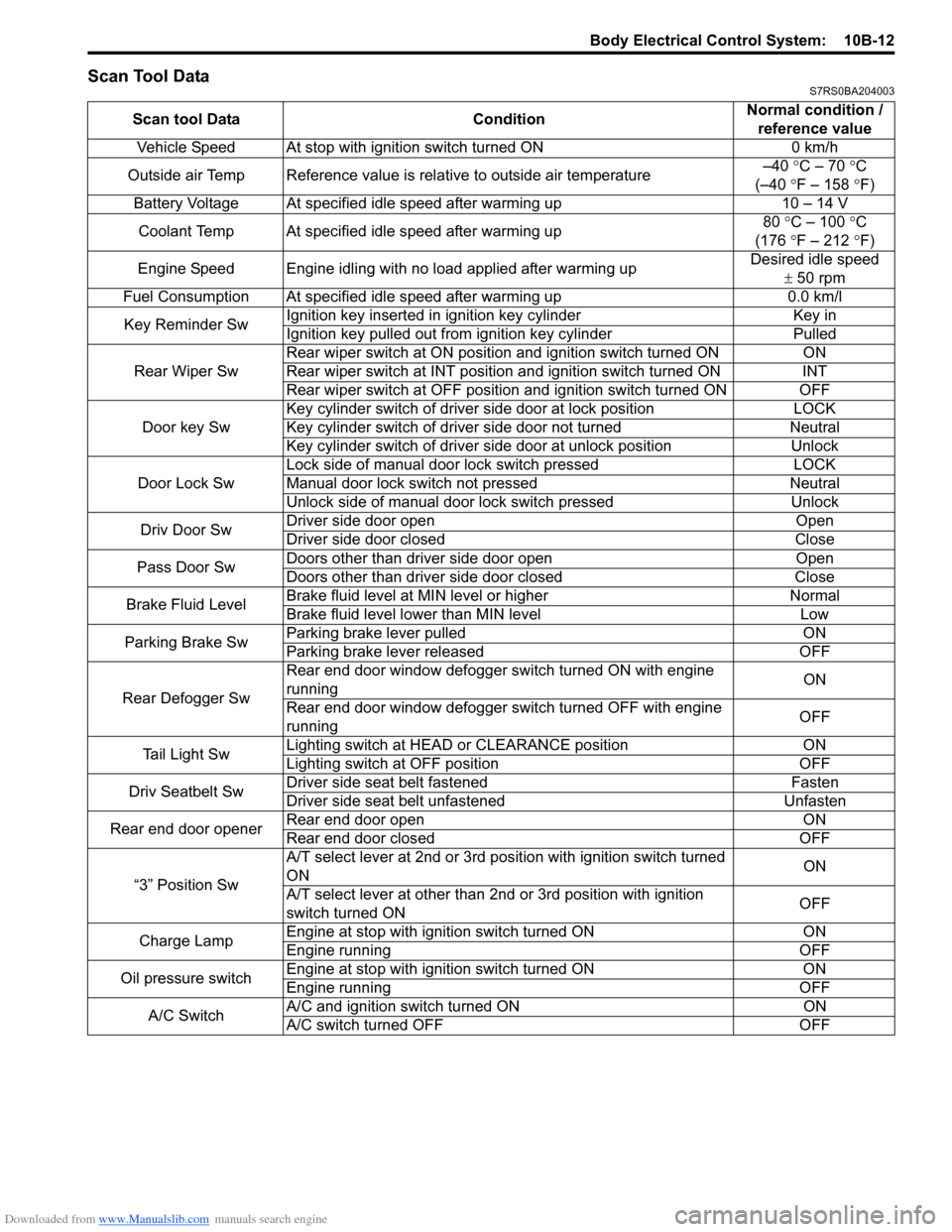
Scan Tool DataS7RS0BA204003
Scan tool DataConditionNormal condition /
reference value
Vehicle Speed At stop with ignition switch turned ON 0 km/h
Outside air Temp Reference value is relative to outside air temperature –40
°C – 70 °C
(–40 °F – 158 ° F)
Battery Voltage At specified idle speed after warming up 10 – 14 V
Coolant Temp At specified idle speed after warming up 80
°C – 100 ° C
(176 °F – 212 ° F)
Engine Speed Engine idling with no load applied after warming up Desired idle speed
± 50 rpm
Fuel Consumption At specified idle speed after warming up 0.0 km/l
Key Reminder Sw Ignition key inserted in
ignition key cylinder Key in
Ignition key pulled out from ignition key cylinder Pulled
Rear Wiper Sw Rear wiper switch at ON position and ignition switch turned ON
ON
Rear wiper switch at INT position and ignition switch turned ON INT
Rear wiper switch at OFF position and ignition switch turned ON OFF
Door key Sw Key cylinder switch of driver side door at lock position
LOCK
Key cylinder switch of driver side door not turned Neutral
Key cylinder switch of driver side door at unlock position Unlock
Door Lock Sw Lock side of manual door lock switch pressed
LOCK
Manual door lock switch not pressed Neutral
Unlock side of manual door lock switch pressed Unlock
Driv Door Sw Driver side door open
Open
Driver side door closed Close
Pass Door Sw Doors other than driver side door open
Open
Doors other than driver side door closed Close
Brake Fluid Level Brake fluid level at MIN level or higher
Normal
Brake fluid level lower than MIN level Low
Parking Brake Sw Parking brake lever pulled
ON
Parking brake lever released OFF
Rear Defogger Sw Rear end door window defogger switch turned ON with engine
running
ON
Rear end door window defogger switch turned OFF with engine
running OFF
Tail Light Sw Lighting switch at HEAD
or CLEARANCE position ON
Lighting switch at OFF position OFF
Driv Seatbelt Sw Driver side seat belt fastened
Fasten
Driver side seat belt unfastened Unfasten
Rear end door opener Rear end door open
ON
Rear end door closed OFF
“3” Position Sw A/T select lever at 2nd or 3rd position with ignition switch turned
ON
ON
A/T select lever at other than 2nd or 3rd position with ignition
switch turned ON OFF
Charge Lamp Engine at stop with ignition switch turned ON
ON
Engine running OFF
Oil pressure switch Engine at stop with ignition switch turned ON
ON
Engine running OFF
A/C Switch A/C and ignition switch turned ON
ON
A/C switch turned OFF OFF