2007 SUZUKI SWIFT Meter
[x] Cancel search: MeterPage 1302 of 1496
Downloaded from www.Manualslib.com manuals search engine 9C-7 Instrumentation / Driver Info. / Horn:
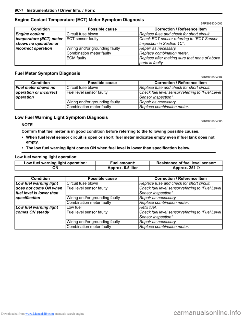
Engine Coolant Temperature (ECT) Meter Symptom DiagnosisS7RS0B9304003
Fuel Meter Symptom DiagnosisS7RS0B9304004
Low Fuel Warning Light Symptom DiagnosisS7RS0B9304005
NOTE
Confirm that fuel meter is in good condition before referring to the following possible causes.
• When fuel level sensor circuit is open or short, fuel meter indicates empty even if fuel tank does not empty.
• The low fuel warning light comes ON when fu el level is lower than specification below.
Low fuel warning light operation:
ConditionPossible cause Correction / Reference Item
Engine coolant
temperature (ECT) meter
shows no operation or
incorrect operation Circuit fuse blown
Replace fuse and check for short circuit.
ECT sensor faulty Check ECT sensor referring to “ECT Sensor
Inspection in Section 1C”.
Wiring and/or grounding faulty Repair as necessary.
Combination meter faulty Replace combination meter.
ECM faulty Replace after making sure that none of above
parts is faulty.
ConditionPossible cause Correction / Reference Item
Fuel meter shows no
operation or incorrect
operation Circuit fuse blown
Replace fuse and check for short circuit.
Fuel level sensor faulty Check fuel level sensor referring to “Fuel Level
Sensor Inspection”.
Wiring and/or grounding faulty Repair as necessary.
Combination meter faulty Replace combination meter.
Low fuel warning light operation: Fuel amount: Resistance of fuel level sensor:
ON Approx. 6.5 liter Approx. 251 Ω
Condition Possible cause Correction / Reference Item
Low fuel warning light
does not come ON when
fuel level is lower than
specification Circuit fuse blown
Replace fuse and check for short circuit.
Fuel level sensor faulty Check fuel level sensor referring to “Fuel Level
Sensor Inspection”.
Wiring and/or grounding faulty Repair as necessary.
Combination meter faulty Replace combination meter.
Low fuel warning light
comes ON steady Low fuel
Refill fuel.
Fuel level sensor faulty Check fuel level sensor referring to “Fuel Level
Sensor Inspection”.
Wiring and/or grounding faulty Repair as necessary.
Combination meter faulty Replace combination meter.
Page 1303 of 1496
Downloaded from www.Manualslib.com manuals search engine Instrumentation / Driver Info. / Horn: 9C-8
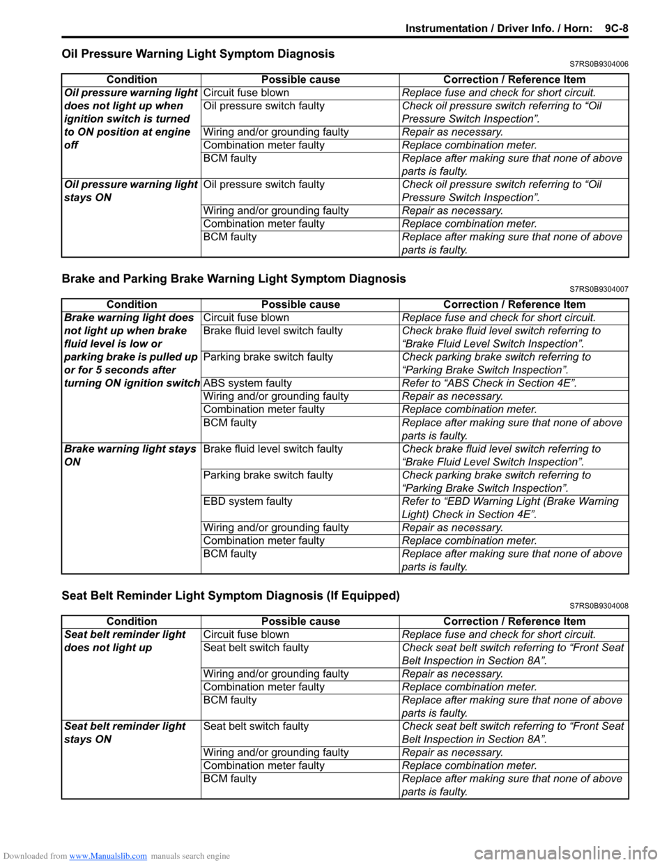
Oil Pressure Warning Light Symptom DiagnosisS7RS0B9304006
Brake and Parking Brake Warning Light Symptom DiagnosisS7RS0B9304007
Seat Belt Reminder Light Symptom Diagnosis (If Equipped)S7RS0B9304008
Condition Possible cause Correction / Reference Item
Oil pressure warning light
does not light up when
ignition switch is turned
to ON position at engine
off Circuit fuse blown
Replace fuse and check for short circuit.
Oil pressure switch faulty Check oil pressure switch referring to “Oil
Pressure Switch Inspection”.
Wiring and/or grounding faulty Repair as necessary.
Combination meter faulty Replace combination meter.
BCM faulty Replace after making sure that none of above
parts is faulty.
Oil pressure warning light
stays ON Oil pressure switch faulty
Check oil pressure switch referring to “Oil
Pressure Switch Inspection”.
Wiring and/or grounding faulty Repair as necessary.
Combination meter faulty Replace combination meter.
BCM faulty Replace after making sure that none of above
parts is faulty.
ConditionPossible cause Correction / Reference Item
Brake warning light does
not light up when brake
fluid level is low or
parking brake is pulled up
or for 5 seconds after
turning ON ignition switch Circuit fuse blown
Replace fuse and check for short circuit.
Brake fluid level switch faulty Check brake fluid level switch referring to
“Brake Fluid Level Switch Inspection”.
Parking brake switch faulty Check parking brake switch referring to
“Parking Brake Switch Inspection”.
ABS system faulty Refer to “ABS Check in Section 4E”.
Wiring and/or grounding faulty Repair as necessary.
Combination meter faulty Replace combination meter.
BCM faulty Replace after making sure that none of above
parts is faulty.
Brake warning light stays
ON Brake fluid level switch faulty
Check brake fluid level switch referring to
“Brake Fluid Level Switch Inspection”.
Parking brake switch faulty Check parking brake switch referring to
“Parking Brake Switch Inspection”.
EBD system faulty Refer to “EBD Warning Light (Brake Warning
Light) Check in Section 4E”.
Wiring and/or grounding faulty Repair as necessary.
Combination meter faulty Replace combination meter.
BCM faulty Replace after making sure that none of above
parts is faulty.
ConditionPossible cause Correction / Reference Item
Seat belt reminder light
does not light up Circuit fuse blown
Replace fuse and check for short circuit.
Seat belt switch faulty Check seat belt switch referring to “Front Seat
Belt Inspection in Section 8A”.
Wiring and/or grounding faulty Repair as necessary.
Combination meter faulty Replace combination meter.
BCM faulty Replace after making sure that none of above
parts is faulty.
Seat belt reminder light
stays ON Seat belt switch faulty
Check seat belt switch referring to “Front Seat
Belt Inspection in Section 8A”.
Wiring and/or grounding faulty Repair as necessary.
Combination meter faulty Replace combination meter.
BCM faulty Replace after making sure that none of above
parts is faulty.
Page 1304 of 1496
Downloaded from www.Manualslib.com manuals search engine 9C-9 Instrumentation / Driver Info. / Horn:
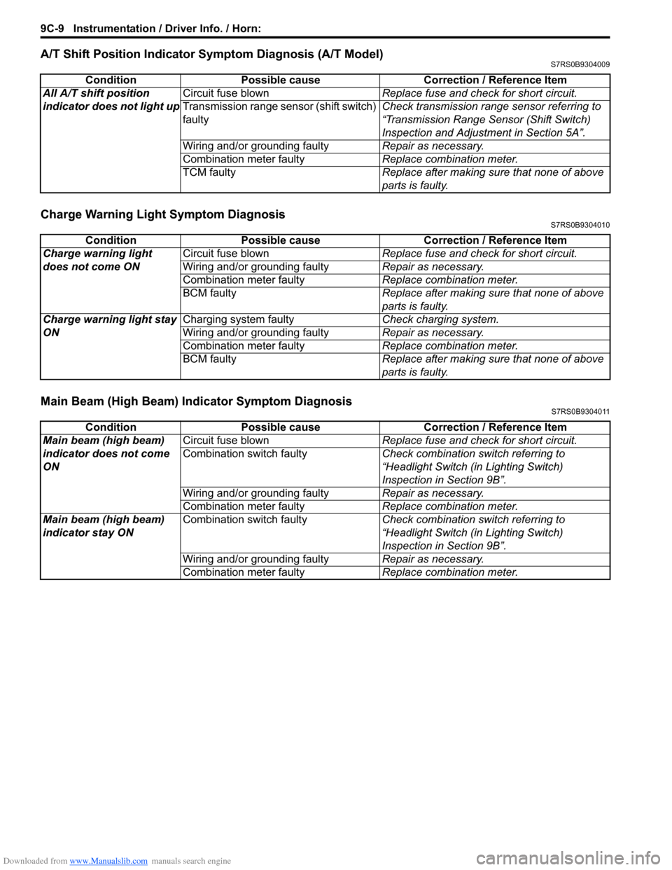
A/T Shift Position Indicator Symptom Diagnosis (A/T Model)S7RS0B9304009
Charge Warning Light Symptom DiagnosisS7RS0B9304010
Main Beam (High Beam) Indicator Symptom DiagnosisS7RS0B9304011
ConditionPossible cause Correction / Reference Item
All A/T shift position
indicator does not light up Circuit fuse blown
Replace fuse and check for short circuit.
Transmission range sens or (shift switch)
faulty Check transmission range sensor referring to
“Transmission Range Sensor (Shift Switch)
Inspection and Adjustment in Section 5A”.
Wiring and/or grounding faulty Repair as necessary.
Combination meter faulty Replace combination meter.
TCM faulty Replace after making sure that none of above
parts is faulty.
ConditionPossible cause Correction / Reference Item
Charge warning light
does not come ON Circuit fuse blown
Replace fuse and check for short circuit.
Wiring and/or grounding faulty Repair as necessary.
Combination meter faulty Replace combination meter.
BCM faulty Replace after making sure that none of above
parts is faulty.
Charge warning light stay
ON Charging system faulty
Check charging system.
Wiring and/or grounding faulty Repair as necessary.
Combination meter faulty Replace combination meter.
BCM faulty Replace after making sure that none of above
parts is faulty.
ConditionPossible cause Correction / Reference Item
Main beam (high beam)
indicator does not come
ON Circuit fuse blown
Replace fuse and check for short circuit.
Combination switch faulty Check combination switch referring to
“Headlight Switch (in Lighting Switch)
Inspection in Section 9B”.
Wiring and/or grounding faulty Repair as necessary.
Combination meter faulty Replace combination meter.
Main beam (high beam)
indicator stay ON Combination switch faulty
Check combination switch referring to
“Headlight Switch (in Lighting Switch)
Inspection in Section 9B”.
Wiring and/or grounding faulty Repair as necessary.
Combination meter faulty Replace combination meter.
Page 1306 of 1496
Downloaded from www.Manualslib.com manuals search engine 9C-11 Instrumentation / Driver Info. / Horn:
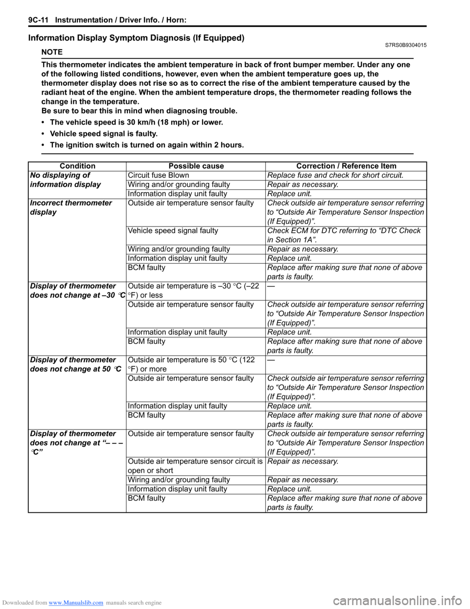
Information Display Symptom Diagnosis (If Equipped)S7RS0B9304015
NOTE
This thermometer indicates the ambient temperature in back of front bumper member. Under any one
of the following listed conditions, however, even when the ambient temperature goes up, the
thermometer display does not rise so as to correct the rise of the ambient temperature caused by the
radiant heat of the engine. When the ambient temperature drops, the thermometer reading follows the
change in the temperature.
Be sure to bear this in mind when diagnosing trouble.
• The vehicle speed is 30 km/h (18 mph) or lower.
• Vehicle speed signal is faulty.
• The ignition switch is turned on again within 2 hours.
ConditionPossible cause Correction / Reference Item
No displaying of
information display Circuit fuse Blown
Replace fuse and check for short circuit.
Wiring and/or grounding faulty Repair as necessary.
Information display unit faulty Replace unit.
Incorrect thermometer
display Outside air temperature sensor faulty
Check outside air temperature sensor referring
to “Outside Air Temperature Sensor Inspection
(If Equipped)”.
Vehicle speed signal faulty Check ECM for DTC referring to “DTC Check
in Section 1A”.
Wiring and/or grounding faulty Repair as necessary.
Information display unit faulty Replace unit.
BCM faulty Replace after making sure that none of above
parts is faulty.
Display of thermometer
does not change at –30
°C Outside air temperature is –30
°C (–22
° F) or less —
Outside air temperature sensor faulty Check outside air temperature sensor referring
to “Outside Air Temperature Sensor Inspection
(If Equipped)”.
Information display unit faulty Replace unit.
BCM faulty Replace after making sure that none of above
parts is faulty.
Display of thermometer
does not change at 50
°C Outside air temperature is 50
°C (122
° F) or more —
Outside air temperature sensor faulty Check outside air temperature sensor referring
to “Outside Air Temperature Sensor Inspection
(If Equipped)”.
Information display unit faulty Replace unit.
BCM faulty Replace after making sure that none of above
parts is faulty.
Display of thermometer
does not change at “– – –
°C” Outside air temperature sensor faulty
Check outside air temperature sensor referring
to “Outside Air Temperature Sensor Inspection
(If Equipped)”.
Outside air temperature sensor circuit is
open or short Repair as necessary.
Wiring and/or grounding faulty Repair as necessary.
Information display unit faulty Replace unit.
BCM faulty Replace after making sure that none of above
parts is faulty.
Page 1310 of 1496
Downloaded from www.Manualslib.com manuals search engine 9C-15 Instrumentation / Driver Info. / Horn:
Combination Meter Removal and InstallationS7RS0B9306003
Removal1) Disconnect negative (–) cable at battery.
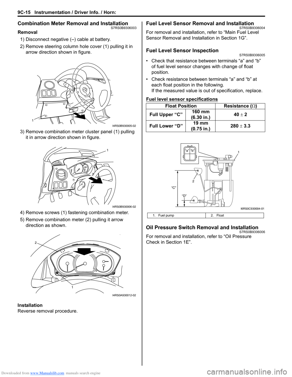
2) Remove steering column hole cover (1) pulling it in arrow direction shown in figure.
3) Remove combination mete r cluster panel (1) pulling
it in arrow direction shown in figure.
4) Remove screws (1) fast ening combination meter.
5) Remove combination me ter (2) pulling it arrow
direction as shown.
Installation
Reverse removal procedure.
Fuel Level Sensor Removal and InstallationS7RS0B9306004
For removal and installation, refer to “Main Fuel Level
Sensor Removal and Installation in Section 1G”.
Fuel Level Sensor InspectionS7RS0B9306005
• Check that resistance between terminals “a” and “b” of fuel level sensor changes with change of float
position.
• Check resistance between terminals “a” and “b” at each float position in the following.
If the measured value is out of specification, replace.
Fuel level sensor specifications
Oil Pressure Switch Removal and InstallationS7RS0B9306006
For removal and installation , refer to “Oil Pressure
Check in Section 1E”.
1
I4RS0B930005-02
1
I4RS0B930006-02
1
2
I4RS0A930012-02
Float Position Resistance (Ω)
Full Upper “C” 160 mm
(6.30 in.) 40
± 2
Full Lower “D” 19 mm
(0.75 in.) 280
± 3.3
1. Fuel pump 2. Float
“b”“a”
2
“C”
“D”
1
I6RS0C930004-01
Page 1312 of 1496
Downloaded from www.Manualslib.com manuals search engine 9C-17 Instrumentation / Driver Info. / Horn:
Door Switch (Front / Rear Door) InspectionS7RS0B9306011
Remove door switch from body and check switch for
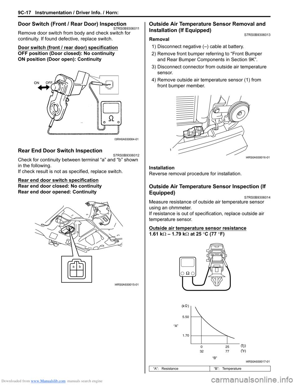
continuity. If found defective, replace switch.
Door switch (front / rear door) specification
OFF position (Door closed): No continuity
ON position (Door open): Continuity
Rear End Door Switch InspectionS7RS0B9306012
Check for continuity between terminal “a” and “b” shown
in the following.
If check result is not as specified, replace switch.
Rear end door switch specification
Rear end door closed: No continuity
Rear end door opened: Continuity
Outside Air Temperature Sensor Removal and
Installation (If Equipped)
S7RS0B9306013
Removal
1) Disconnect negative (–) cable at battery.
2) Remove front bumper referring to “Front Bumper and Rear Bumper Components in Section 9K”.
3) Disconnect connector from outside air temperature sensor.
4) Remove outside air temperature sensor (1) from front bumper member.
Installation
Reverse removal procedure for installation.
Outside Air Temperature Sensor Inspection (If
Equipped)
S7RS0B9306014
Measure resistance of outside air temperature sensor
using an ohmmeter.
If resistance is out of specif ication, replace outside air
temperature sensor.
Outside air temperature sensor resistance
1.61 kΩ – 1.79 k Ω at 25 °C (77 °F)
I3RH0A930004-01
a
b
I4RS0A930015-01
“A”: Resistance “B”: Temperature
1
I4RS0A930016-01
“B”
“A”
5.50
1.70 0
32 25
77
F
I4RS0A930017-01
Page 1325 of 1496
Downloaded from www.Manualslib.com manuals search engine Wipers / Washers: 9D-8
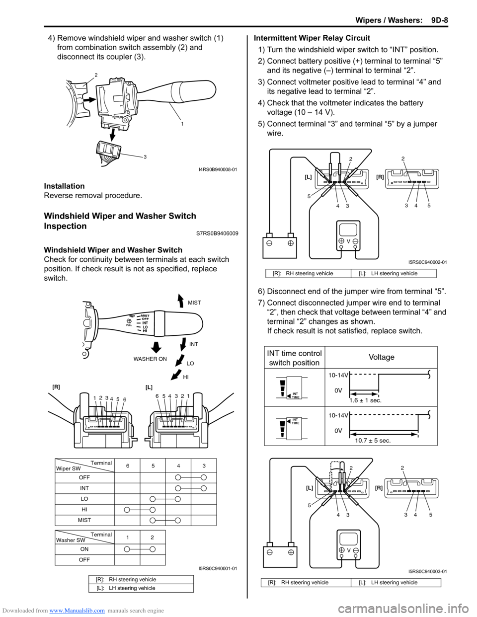
4) Remove windshield wiper and washer switch (1) from combination swit ch assembly (2) and
disconnect its coupler (3).
Installation
Reverse removal procedure.
Windshield Wiper and Washer Switch
Inspection
S7RS0B9406009
Windshield Wiper and Washer Switch
Check for continuity between terminals at each switch
position. If check result is not as specified, replace
switch. Intermittent Wiper Relay Circuit
1) Turn the windshield wiper switch to “INT” position.
2) Connect battery positive (+ ) terminal to terminal “5”
and its negative (–) terminal to terminal “2”.
3) Connect voltmeter positive lead to terminal “4” and its negative lead to terminal “2”.
4) Check that the voltmeter indicates the battery voltage (10 – 14 V).
5) Connect terminal “3” and terminal “5” by a jumper wire.
6) Disconnect end of the jumper wire from terminal “5”.
7) Connect disconnected jumper wire end to terminal “2”, then check that voltage between terminal “4” and
terminal “2” changes as shown.
If check result is not satisfied, replace switch.
[R]: RH steering vehicle
[L]: LH steering vehicle
1
2
3
I4RS0B940008-01
Terminal
Wiper SW
OFF
INT 6543
MIST
Terminal
Washer SW
OFF 12
ONLO
HI
654321
MIST
INT
LO
HI
WASHER ON
1
2
3
4 5 6
[R]
[L]
I5RS0C940001-01
[R]: RH steering vehicle [L]: LH steering vehicle
[R]: RH steering vehicle [L]: LH steering vehicle
V
2
34
52
34 5
[L] [R]
I5RS0C940002-01
V
INT
TIME
INT
TIME
INT time control
switch position Voltage
10-14V
0V 1.6 ± 1 sec.
10-14V
0V 10.7 ± 5 sec.
2
34
52
34 5
[L]
[R]
I5RS0C940003-01
Page 1326 of 1496
Downloaded from www.Manualslib.com manuals search engine 9D-9 Wipers / Washers:
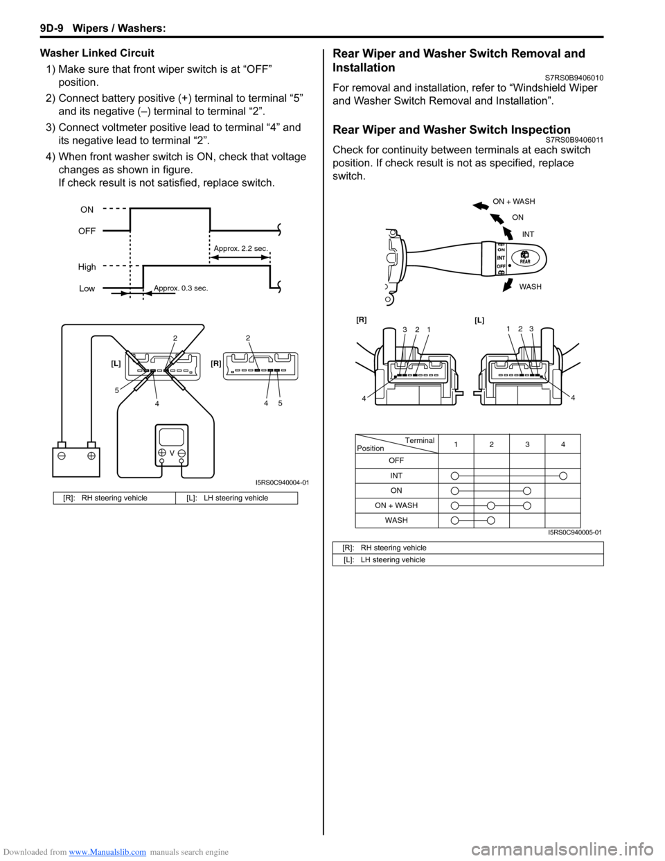
Washer Linked Circuit1) Make sure that front wiper switch is at “OFF” position.
2) Connect battery positive (+ ) terminal to terminal “5”
and its negative (–) terminal to terminal “2”.
3) Connect voltmeter positive lead to terminal “4” and its negative lead to terminal “2”.
4) When front washer switch is ON, check that voltage
changes as shown in figure.
If check result is not satisfied, replace switch.Rear Wiper and Washer Switch Removal and
Installation
S7RS0B9406010
For removal and installation, refer to “Windshield Wiper
and Washer Switch Removal and Installation”.
Rear Wiper and Washer Switch InspectionS7RS0B9406011
Check for continuity between terminals at each switch
position. If check result is not as specified, replace
switch.
[R]: RH steering vehicle [L]: LH steering vehicle
V
2
4
52
45
[L] [R]
ON
OFF
High Low
Approx. 0.3 sec. Approx. 2.2 sec.
I5RS0C940004-01
[R]: RH steering vehicle
[L]: LH steering vehicle
Terminal
Position
OFF
INT 4
3
12
WASH ON
ON + WASH
ON + WASH
INT
ON
WASH
123
4
[R]
[L]123
4
I5RS0C940005-01