Page 1483 of 1496

Downloaded from www.Manualslib.com manuals search engine Keyless Start System: 10E-21
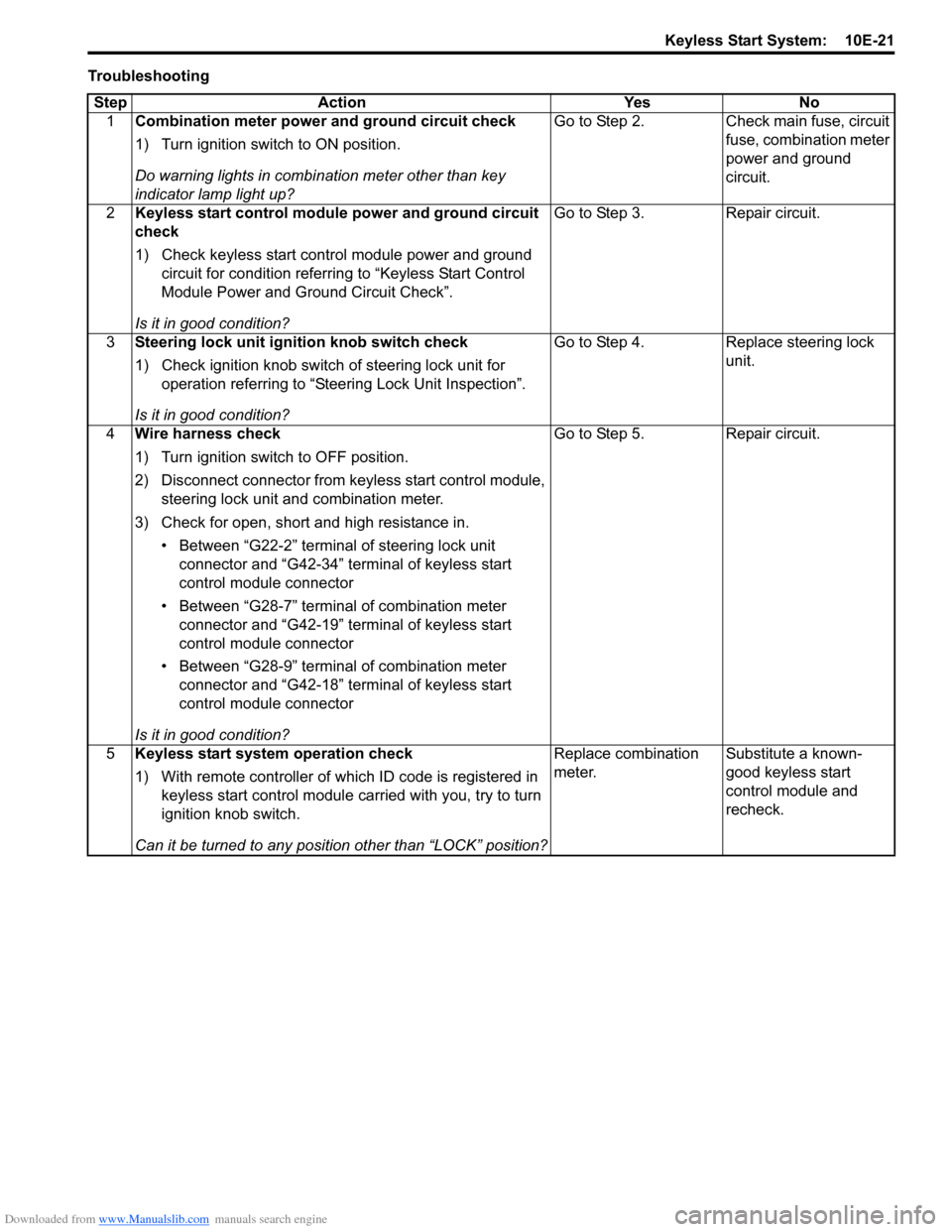
TroubleshootingStep Action Yes No 1 Combination meter power and ground circuit check
1) Turn ignition switch to ON position.
Do warning lights in combi nation meter other than key
indicator lamp light up? Go to Step 2. Check main fuse, circuit
fuse, combination meter
power and ground
circuit.
2 Keyless start control module power and ground circuit
check
1) Check keyless start control module power and ground
circuit for condition referrin g to “Keyless Start Control
Module Power and Ground Circuit Check”.
Is it in good condition? Go to Step 3. Repair circuit.
3 Steering lock unit ignition knob switch check
1) Check ignition knob switch of steering lock unit for
operation referring to “Steering Lock Unit Inspection”.
Is it in good condition? Go to Step 4. Replace steering lock
unit.
4 Wire harness check
1) Turn ignition switch to OFF position.
2) Disconnect connector from ke yless start control module,
steering lock unit and combination meter.
3) Check for open, short and high resistance in. • Between “G22-2” terminal of steering lock unit connector and “G42-34” terminal of keyless start
control module connector
• Between “G28-7” terminal of combination meter connector and “G42-19” terminal of keyless start
control module connector
• Between “G28-9” terminal of combination meter connector and “G42-18” terminal of keyless start
control module connector
Is it in good condition? Go to Step 5. Repair circuit.
5 Keyless start system operation check
1) With remote controller of which ID code is registered in
keyless start control module carried with you, try to turn
ignition knob switch.
Can it be turned to any position other than “LOCK” position? Replace combination
meter.
Substitute a known-
good keyless start
control module and
recheck.
Page 1485 of 1496

Downloaded from www.Manualslib.com manuals search engine Keyless Start System: 10E-23
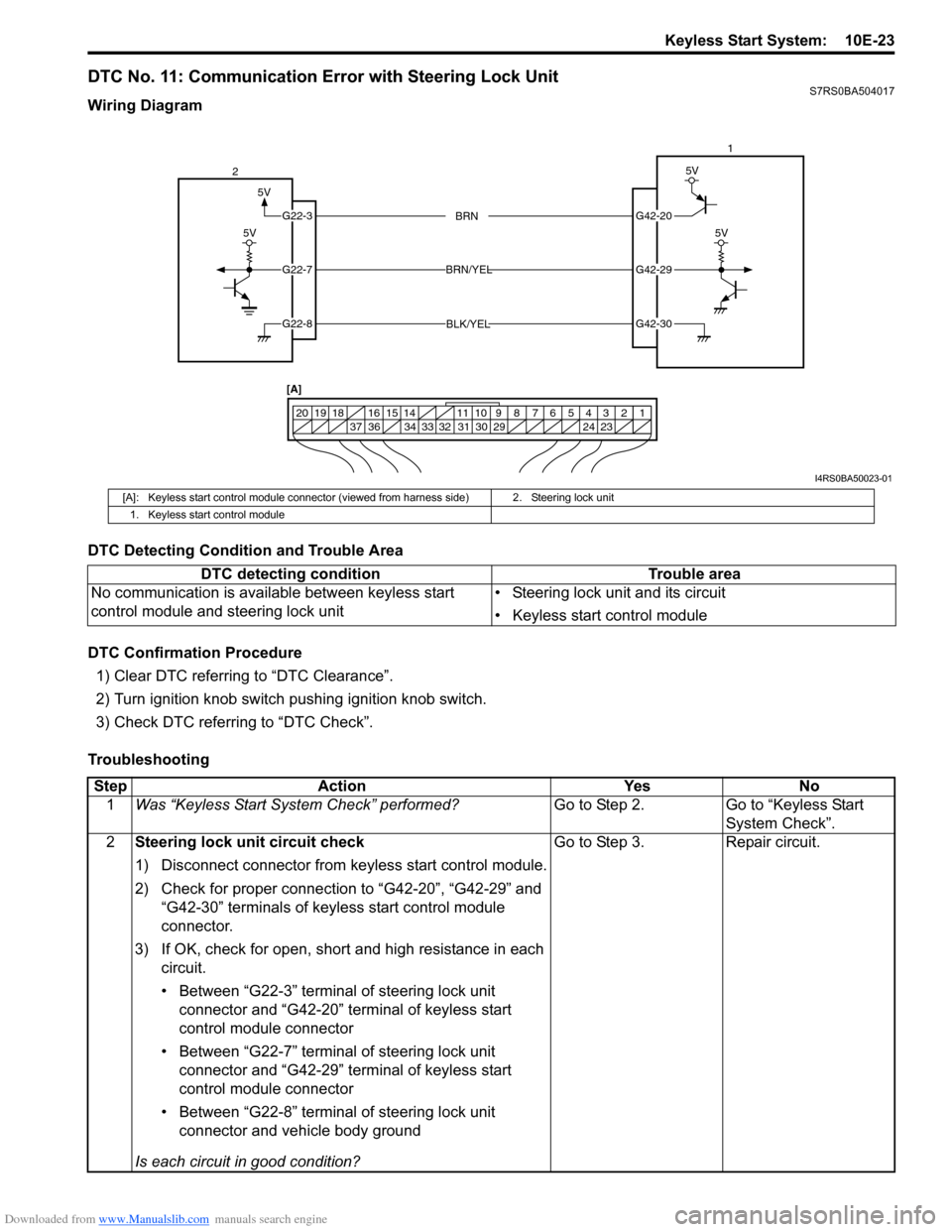
DTC No. 11: Communication Error with Steering Lock UnitS7RS0BA504017
Wiring Diagram
DTC Detecting Condition and Trouble Area
DTC Confirmation Procedure1) Clear DTC referring to “DTC Clearance”.
2) Turn ignition knob switch pushing ignition knob switch.
3) Check DTC referring to “DTC Check”.
Troubleshooting
5V
G42-20
G42-29
G42-30
G22-3
G22-7
G22-8
1234567891011
141516
36 34 33 32 31 30 29 24 23
37
181920
5V
5V
BRN
BRN/YEL
BLK/YEL
5V
2 1
[A]
I4RS0BA50023-01
[A]: Keyless start control module connector (vie wed from harness side) 2. Steering lock unit
1. Keyless start control module
DTC detecting condition Trouble area
No communication is available between keyless start
control module and steering lock unit • Steering lock unit and its circuit
• Keyless start control module
Step
Action YesNo
1 Was “Keyless Start System Check” performed? Go to Step 2.Go to “Keyless Start
System Check”.
2 Steering lock unit circuit check
1) Disconnect connector from keyless start control module.
2) Check for proper connection to “G42-20”, “G42-29” and
“G42-30” terminals of keyless start control module
connector.
3) If OK, check for open, short and high resistance in each circuit.
• Between “G22-3” terminal of steering lock unit connector and “G42-20” terminal of keyless start
control module connector
• Between “G22-7” terminal of steering lock unit connector and “G42-29” terminal of keyless start
control module connector
• Between “G22-8” terminal of steering lock unit connector and vehicle body ground
Is each circuit in good condition? Go to Step 3.
Repair circuit.
Page 1486 of 1496

Downloaded from www.Manualslib.com manuals search engine 10E-24 Keyless Start System:
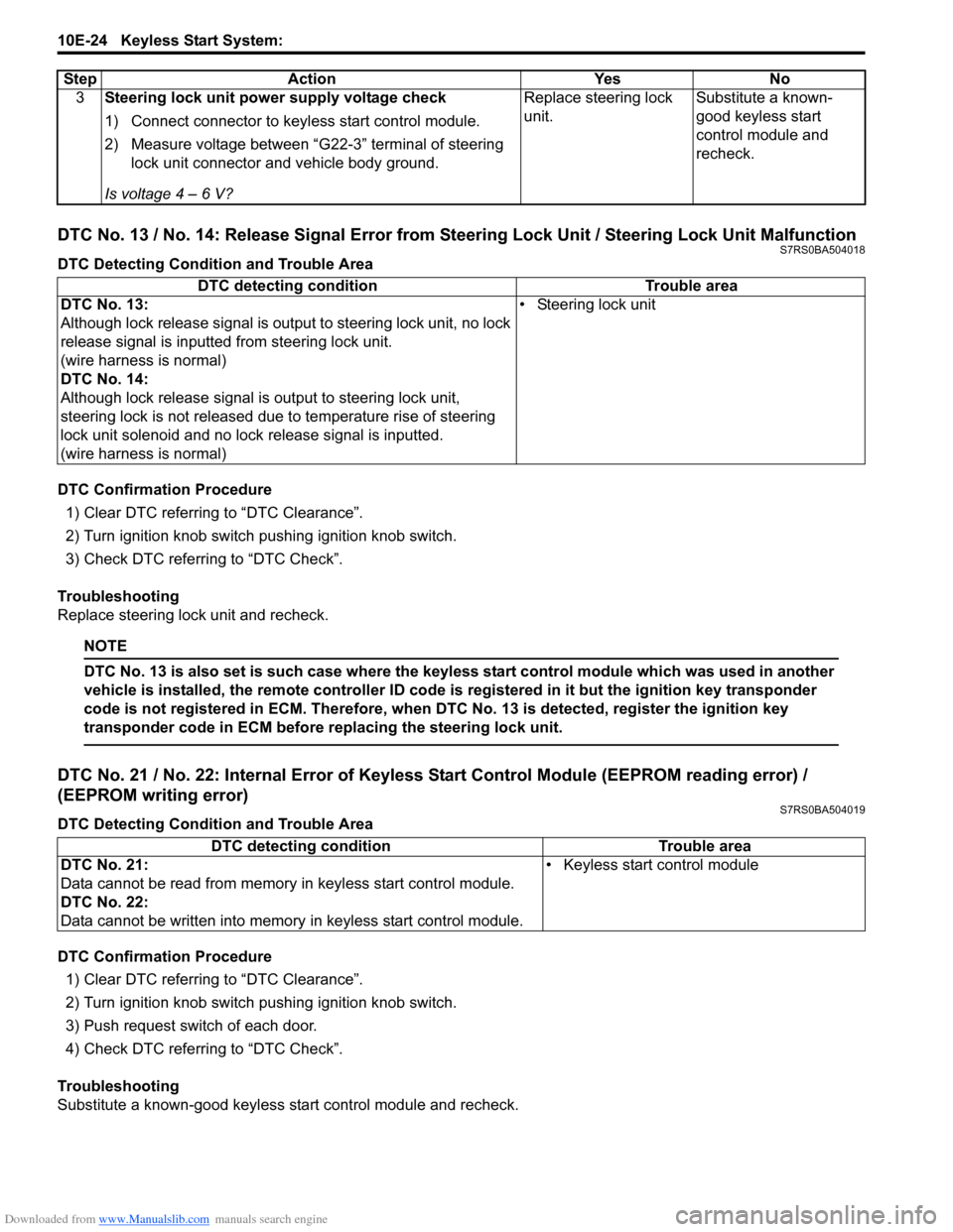
DTC No. 13 / No. 14: Release Signal Error from Steering Lock Unit / Steering Lock Unit MalfunctionS7RS0BA504018
DTC Detecting Condition and Trouble Area
DTC Confirmation Procedure1) Clear DTC referring to “DTC Clearance”.
2) Turn ignition knob switch pushing ignition knob switch.
3) Check DTC referring to “DTC Check”.
Troubleshooting
Replace steering lock unit and recheck.
NOTE
DTC No. 13 is also set is such case where the keyless start control module which was used in another
vehicle is installed, the remote controller ID code is registered in it but the ignition key transponder
code is not registered in ECM. Therefore, when DTC No. 13 is detected, register the ignition key
transponder code in ECM before replacing the steering lock unit.
DTC No. 21 / No. 22: Internal Error of Keyle ss Start Control Module (EEPROM reading error) /
(EEPROM writing error)
S7RS0BA504019
DTC Detecting Condition and Trouble Area
DTC Confirmation Procedure
1) Clear DTC referring to “DTC Clearance”.
2) Turn ignition knob switch pushing ignition knob switch.
3) Push request switch of each door.
4) Check DTC referring to “DTC Check”.
Troubleshooting
Substitute a known-good keyless start control module and recheck. 3
Steering lock unit power supply voltage check
1) Connect connector to keyl ess start control module.
2) Measure voltage between “G22-3” terminal of steering lock unit connector and vehicle body ground.
Is voltage 4 – 6 V? Replace steering lock
unit.
Substitute a known-
good keyless start
control module and
recheck.
Step Action Yes No
DTC detecting condition
Trouble area
DTC No. 13:
Although lock release signal is ou tput to steering lock unit, no lock
release signal is inputted from steering lock unit.
(wire harness is normal)
DTC No. 14:
Although lock release signal is output to steering lock unit,
steering lock is not released due to temperature rise of steering
lock unit solenoid and no lock release signal is inputted.
(wire harness is normal) • Steering lock unit
DTC detecting condition Trouble area
DTC No. 21:
Data cannot be read from memory in keyless start control module.
DTC No. 22:
Data cannot be written into memory in keyless start control module.• Keyless start control module
Page 1494 of 1496

Downloaded from www.Manualslib.com manuals search engine 10E-32 Keyless Start System:
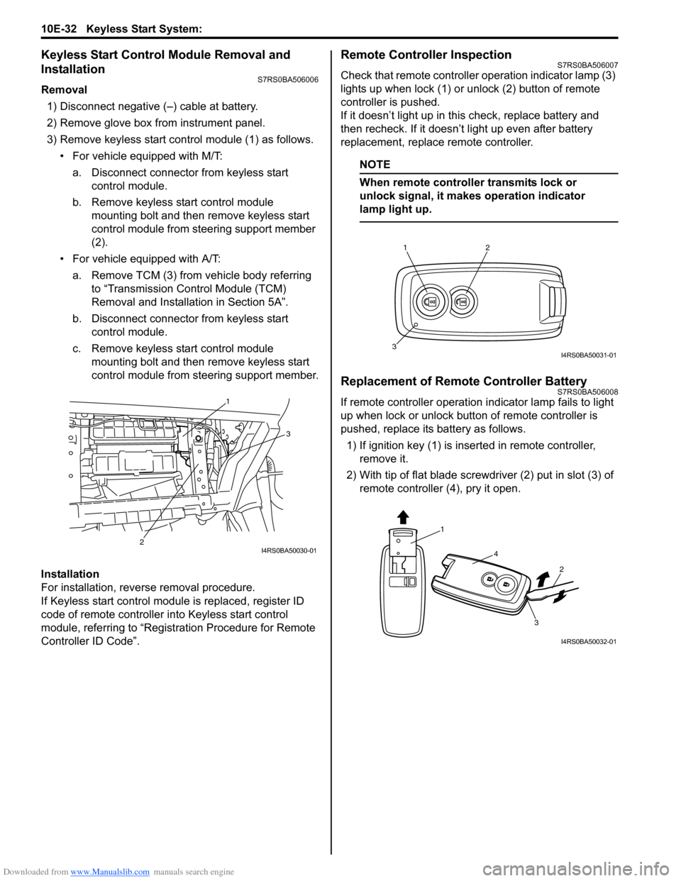
Keyless Start Control Module Removal and
Installation
S7RS0BA506006
Removal1) Disconnect negative (–) cable at battery.
2) Remove glove box from instrument panel.
3) Remove keyless start cont rol module (1) as follows.
• For vehicle equipped with M/T:
a. Disconnect connector from keyless start control module.
b. Remove keyless start control module mounting bolt and then remove keyless start
control module from steering support member
(2).
• For vehicle equipped with A/T: a. Remove TCM (3) from vehicle body referring to “Transmission Control Module (TCM)
Removal and Installation in Section 5A”.
b. Disconnect connector from keyless start control module.
c. Remove keyless start control module mounting bolt and then remove keyless start
control module from steering support member.
Installation
For installation, reverse removal procedure.
If Keyless start control module is replaced, register ID
code of remote controller in to Keyless start control
module, referring to “Registration Procedure for Remote
Controller ID Code”.
Remote Controller InspectionS7RS0BA506007
Check that remote controller operation indicator lamp (3)
lights up when lock (1) or un lock (2) button of remote
controller is pushed.
If it doesn’t light up in this check, replace battery and
then recheck. If it doesn’t light up even after battery
replacement, replace remote controller.
NOTE
When remote controller transmits lock or
unlock signal, it makes operation indicator
lamp light up.
Replacement of Remote Controller BatteryS7RS0BA506008
If remote controller operation i ndicator lamp fails to light
up when lock or unlock button of remote controller is
pushed, replace its battery as follows.
1) If ignition key (1) is inse rted in remote controller,
remove it.
2) With tip of flat blade screwdriver (2) put in slot (3) of remote controller (4), pry it open.1
3
2
I4RS0BA50030-01
12
3I4RS0BA50031-01
1
4
2
3
I4RS0BA50032-01