2007 SUZUKI SWIFT Repair circuit
[x] Cancel search: Repair circuitPage 989 of 1496
Downloaded from www.Manualslib.com manuals search engine Air Conditioning System: Automatic Type 7B-41
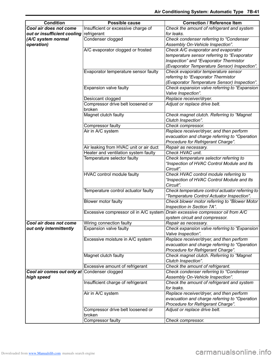
Cool air does not come
out or insufficient cooling
(A/C system normal
operation)Insufficient or excessive charge of
refrigerant
Check the amount of refrigerant and system
for leaks.
Condenser clogged Check condenser referring to “Condenser
Assembly On-Vehicle Inspection”.
A/C evaporator clogged or frosted Check A/C evaporator and evaporator
temperature sensor referring to “Evaporator
Inspection” and “Evaporator Thermistor
(Evaporator Temperature Sensor) Inspection”.
Evaporator temperature sensor faulty Check evaporator temperature sensor
referring to “Evaporator Thermistor
(Evaporator Temperature Sensor) Inspection”.
Expansion valve faulty Check expansion valve referring to “Expansion
Valve Inspection”.
Desiccant clogged Replace receiver/dryer.
Compressor drive belt loosened or
broken Adjust or replace drive belt.
Magnet clutch faulty Check magnet clutch. Referring to “Magnet
Clutch Inspection”.
Compressor faulty Check compressor.
Air in A/C system Replace receiver/dryer, and then perform
evacuation and charge referring to “Operation
Procedure for Refrigerant Charge”.
Air leaking from HVAC unit or air duct Repair as necessary.
Heater and ventilation system faulty Check HVAC unit.
Temperature selector faulty Check temperature selector referring to
“Inspection of HVAC Control Module and Its
Circuit”.
HVAC control module faulty Check HVAC control module referring to
“Inspection of HVAC Control Module and Its
Circuit”.
Temperature control actuator faulty Check temperature control actuator referring to
“Temperature Control Actuator Inspection”.
Blower motor faulty Check blower motor referring to “Blower Motor
Inspection in Section 7A”.
Excessive compressor oil in A/C system Drain excessive compressor oil from A/C
system circuit and compressor.
Cool air does not come
out only intermittently Wiring connection faulty
Repair as necessary.
Expansion valve faulty Check expansion valve referring to “Expansion
Valve Inspection”.
Excessive moisture in A/C system Replace receiver/dryer, and then perform
evacuation and charge referring to “Operation
Procedure for Refrigerant Charge”.
Magnet clutch faulty Check magnet clutch. Referring to “Magnet
Clutch Inspection”.
Excessive amount of refrigerant Check the amount of refrigerant.
Cool air comes out only at
high speed Condenser clogged
Check condenser referring to “Condenser
Assembly On-Vehicle Inspection”.
Insufficient charge of refrigerant Check the amount of refrigerant and system
for leaks.
Air in A/C system Replace receiver/dryer, and then perform
evacuation and charge referring to “Operation
Procedure for Refrigerant Charge”.
Compressor drive belt loosened or
broken Adjust or replace drive belt.
Compressor faulty Check compressor.
Condition Possible cause Correction / Reference Item
Page 996 of 1496
Downloaded from www.Manualslib.com manuals search engine 7B-48 Air Conditioning System: Automatic Type
Description for Each Step
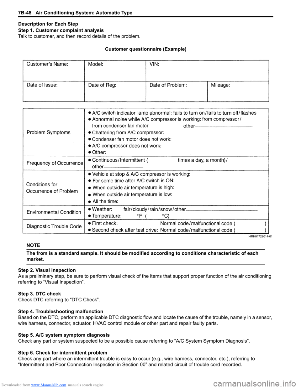
Step 1. Customer complaint analysis
Talk to customer, and then record details of the problem.
Customer questionnaire (Example)
NOTE
The from is a standard sample. It should be modified according to conditions characteristic of each
market.
Step 2. Visual inspection
As a preliminary step, be sure to perform visual check of th e items that support proper function of the air conditioning
referring to “Visual Inspection”.
Step 3. DTC check
Check DTC referring to “DTC Check”.
Step 4. Troubleshooting malfunction
Based on the DTC, perform an applicable DTC diagnostic flow and locate the cause of the trouble, namely in a sensor,
wire harness, connector, actuat or, HVAC control module or other part and repair faulty parts.
Step 5. A/C system symptom diagnosis
Check any part or system suspected to be a possible cause referring to “A/C System Symptom Diagnosis”.
Step 6. Check for intermittent problem
Check any part where an intermittent trouble is easy to oc cur (e.g., wire harness, connector, etc.), referring to
“Intermittent and Poor Connection Inspection in Sect ion 00” and related circuit of trouble cord recorded.
I4RH01722014-01
Page 1007 of 1496
Downloaded from www.Manualslib.com manuals search engine Air Conditioning System: Automatic Type 7B-59
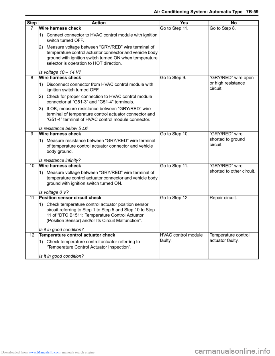
7Wire harness check
1) Connect connector to HVAC control module with ignition
switch turned OFF.
2) Measure voltage between “GRY/RED” wire terminal of temperature control actuator connector and vehicle body
ground with ignition switch turned ON when temperature
selector is operation to HOT direction.
Is voltage 10 – 14 V? Go to Step 11. Go to Step 8.
8 Wire harness check
1) Disconnect connector from HVAC control module with
ignition switch turned OFF.
2) Check for proper connection to HVAC control module connector at “G51-3” and “G51-4” terminals.
3) If OK, measure resistance between “GRY/RED” wire terminal of temperature control actuator connector and
“G51-4” terminal of HVAC control module connector.
Is resistance below 5
Ω? Go to Step 9. “GRY/RED” wire open
or high resistance
circuit.
9 Wire harness check
1) Measure resistance between “GRY/RED” wire terminal
of temperature control actuator connector and vehicle
body ground.
Is resistance infinity? Go to Step 10. “GRY/RED” wire
shorted to ground
circuit.
10 Wire harness check
1) Measure voltage between “GRY/RED” wire terminal of
temperature control actuator connector and vehicle body
ground with ignition switch turned ON.
Is voltage 0 V? Go to Step 11. “GRY/RED” wire
shorted to other circuit.
11 Position sensor circuit check
1) Check temperature control actuator position sensor
circuit referring to Step 1 to Step 5 and Step 10 to Step
11 of “DTC B1511: Temperature Control Actuator
(Position Sensor) and/or Its Circuit Malfunction”.
Is it in good condition? Go to Step 12. Repair circuit.
12 Temperature control actuator check
1) Check temperature control actuator referring to
“Temperature Control Actuator Inspection”.
Is it in good condition? HVAC control module
faulty.
Temperature control
actuator faulty.
Step Action Yes No
Page 1010 of 1496
Downloaded from www.Manualslib.com manuals search engine 7B-62 Air Conditioning System: Automatic Type
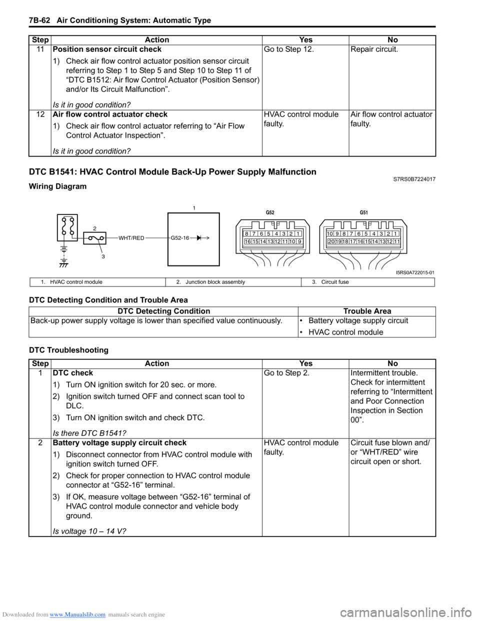
DTC B1541: HVAC Control Module Back-Up Power Supply MalfunctionS7RS0B7224017
Wiring Diagram
DTC Detecting Condition and Trouble Area
DTC Troubleshooting11
Position sensor circuit check
1) Check air flow control actuator position sensor circuit
referring to Step 1 to Step 5 and Step 10 to Step 11 of
“DTC B1512: Air flow Control Actuator (Position Sensor)
and/or Its Circuit Malfunction”.
Is it in good condition? Go to Step 12. Repair circuit.
12 Air flow control actuator check
1) Check air flow control actuator referring to “Air Flow
Control Actuator Inspection”.
Is it in good condition? HVAC control module
faulty.
Air flow control actuator
faulty.
Step Action Yes No
WHT/RED
2 17812910
65 431516 14 13 12 11
G52
789101920121112
65 431718 16 15 14 13
G51
3
G52-16
I5RS0A722015-01
1. HVAC control module
2. Junction block assembly 3. Circuit fuse
DTC Detecting Condition Trouble Area
Back-up power supply voltage is lo wer than specified value continuously. • Battery voltage supply circuit
• HVAC control module
StepAction YesNo
1 DTC check
1) Turn ON ignition switch for 20 sec. or more.
2) Ignition switch turned OF F and connect scan tool to
DLC.
3) Turn ON ignition switch and check DTC.
Is there DTC B1541? Go to Step 2.
Intermittent trouble.
Check for intermittent
referring to “Intermittent
and Poor Connection
Inspection in Section
00”.
2 Battery voltage supply circuit check
1) Disconnect connector from HVAC control module with
ignition switch turned OFF.
2) Check for proper connection to HVAC control module connector at “G52-16” terminal.
3) If OK, measure voltage between “G52-16” terminal of HVAC control module connector and vehicle body
ground.
Is voltage 10 – 14 V? HVAC control module
faulty.
Circuit fuse blown and/
or “WHT/RED” wire
circuit open or short.
Page 1011 of 1496
Downloaded from www.Manualslib.com manuals search engine Air Conditioning System: Automatic Type 7B-63
DTC B1546: A/C Refrigerant Pressure MalfunctionS7RS0B7224018
DTC Detecting Condition and Trouble Area
DTC Troubleshooting
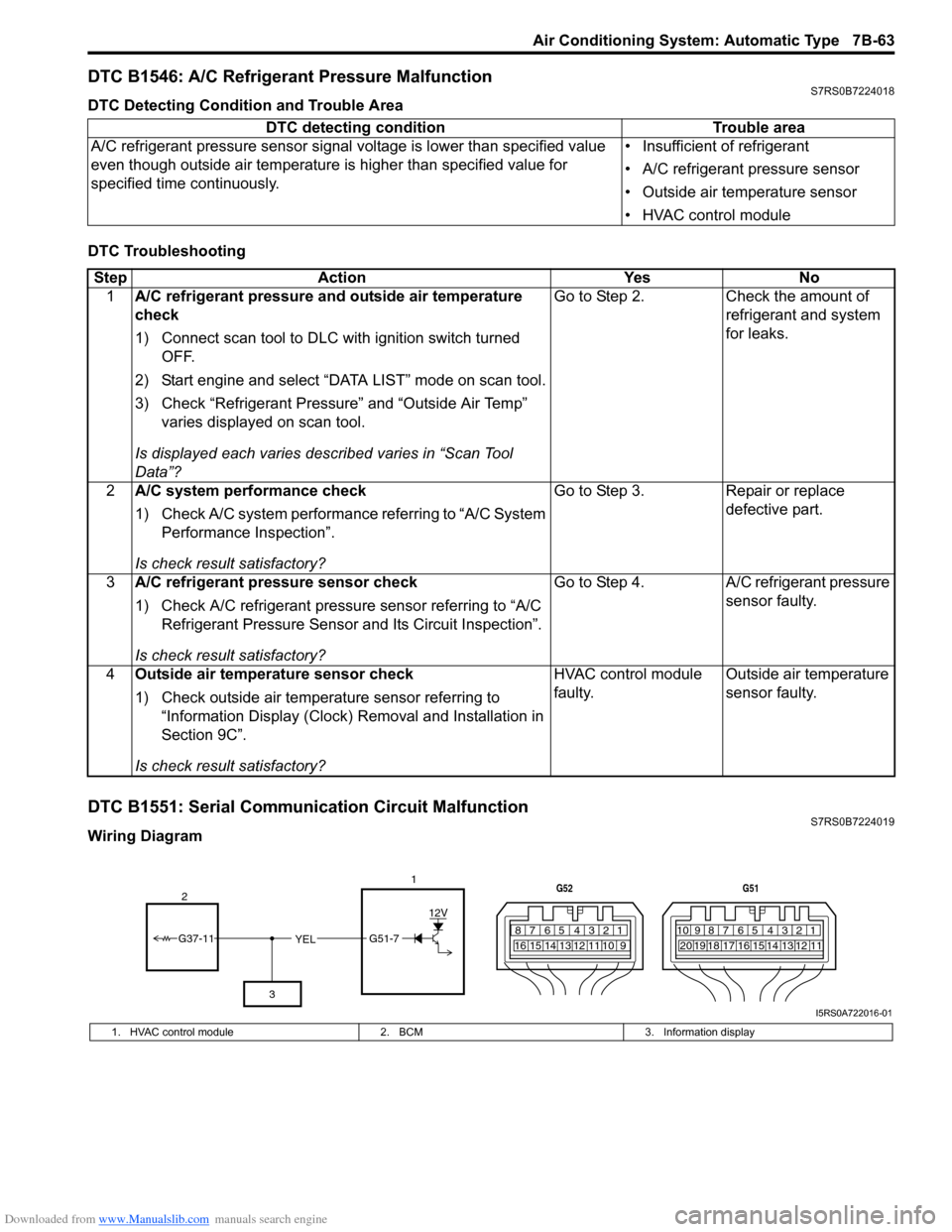
DTC B1551: Serial Communication Circuit MalfunctionS7RS0B7224019
Wiring DiagramDTC detecting condition Trouble area
A/C refrigerant pressure sensor signal voltage is lower t han specified value
even though outside air temperature is higher than specified value for
specified time continuously. • Insufficient of refrigerant
• A/C refrigerant pressure sensor
• Outside air temperature sensor
• HVAC control module
Step
Action YesNo
1 A/C refrigerant pressure and outside air temperature
check
1) Connect scan tool to DLC with ignition switch turned
OFF.
2) Start engine and select “DATA LIST” mode on scan tool.
3) Check “Refrigerant Pressure” and “Outside Air Temp” varies displayed on scan tool.
Is displayed each va ries described varies in “Scan Tool
Data”? Go to Step 2.
Check the amount of
refrigerant and system
for leaks.
2 A/C system performance check
1) Check A/C system performance referring to “A/C System
Performance Inspection”.
Is check result satisfactory? Go to Step 3.
Repair or replace
defective part.
3 A/C refrigerant pressure sensor check
1) Check A/C refrigerant pressure sensor referring to “A/C
Refrigerant Pressure Sensor and Its Circuit Inspection”.
Is check result satisfactory? Go to Step 4.
A/C refrigerant pressure
sensor faulty.
4 Outside air temperature sensor check
1) Check outside air temperature sensor referring to
“Information Display (Clock) Removal and Installation in
Section 9C”.
Is check result satisfactory? HVAC control module
faulty.
Outside air temperature
sensor faulty.
YEL17812910
65 431516 14 13 12 11
G52
789101920121112
65 431718 16 15 14 13
G51
G51-7
12V
2
3
G37-11
I5RS0A722016-01
1. HVAC control module 2. BCM3. Information display
Page 1019 of 1496
Downloaded from www.Manualslib.com manuals search engine Air Conditioning System: Automatic Type 7B-71
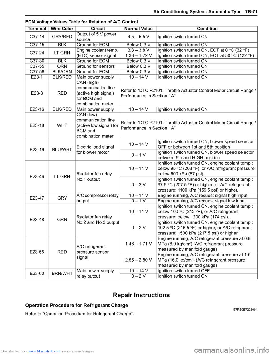
ECM Voltage Values Table for Relation of A/C Control
Repair Instructions
Operation Procedure for Refrigerant ChargeS7RS0B7226001
Refer to “Operation Procedure for Refrigerant Charge”.Terminal Wire Color Circuit Normal Value Condition
C37-14 GRY/RED Output of 5 V power
source 4.5 – 5.5 V Ignition switch turned ON
C37-15 BLK Ground for ECM Below 0.3 V Ignition switch turned ON
C37-24 LT GRN Engine coolant temp.
(ETC) sensor signal 3.3 – 3.8 V Ignition switch turned ON, ECT at 0
°C (32 ° F)
1.38 – 1.72 V Ignition switch turned ON, ECT at 50 °C (122 °F)
C37-30 BLK Ground for ECM Below 0.3 V Ignition switch turned ON
C37-55 ORN Ground for sensors Below 0.3 V Ignition switch turned ON
C37-58 BLK/ORN Ground for ECM Below 0.3 V Ignition switch turned ON E23-1 BLK/RED Main power supply 10 – 14 V Ignition switch turned ON
E23-3 RED CAN (high)
communication line
(active high signal)
for BCM and
combination meterRefer to “DTC P2101: Throttle Actu
ator Control Motor Circuit Range /
Performance in Section 1A”
E23-16 BLK/RED Main power supply 10 – 14 V Ignition switch turned ON
E23-18 WHT CAN (low)
communication line
(active low signal) for
BCM and
combination meterRefer to “DTC P2101: Throttle Actu
ator Control Motor Circuit Range /
Performance in Section 1A”
E23-19 BLU/WHT Electric load signal
for blower motor 10 – 14 V
Ignition switch turned ON, blower speed selector
OFF or between 1st and 5th position
0 – 1 V Ignition switch turned ON, blower speed selector
between 6th and HIGH position
E23-46 LT GRN Radiator fan relay
No.1 output 10 – 14 V
Ignition switch turned ON, engine coolant temp.:
below 95
°C (203 ° F), or A/C refrigerant pressure:
below 600 kPa (87 psi).
0 – 2 V Ignition switch turned ON, engine coolant temp.:
97.5
°C (207.5 °F) or higher, or A/C refrigerant
pressure: 1100 kPa (159.5 psi) or higher.
E23-47 GRY A/C compressor relay
output 10 – 14 V Engine running, A/C request signal high input
0 – 1 V Engine running, A/C request signal low input
E23-48 GRN Radiator fan relay
No.2 and No.3 output 10 – 14 V
Ignition switch turned ON, engine coolant temp.:
below 100
°C (212 °F), or A/C refrigerant
pressure: below 1200 kPa (174 psi).
0 – 2 V Ignition switch turned ON, engine coolant temp.:
102.5
°C (216.5 ° F) or higher, or A/C refrigerant
pressure: 1500 kPa (217.5 psi) or higher.
E23-55 RED A/C refrigerant
pressure sensor
signal 1.46 – 1.71 V
Engine running, A/C refrigerant pressure at 0.8
MPa (8.0 kg/cm
2) (A/C refrigerant pressure
measured by manifold gauge)
2.55 – 2.80 V Engine running, A/C refrigerant pressure at 1.6
MPa (16.0 kg/cm
2) (A/C refrigerant pressure
measured by manifold gauge)
E23-60 BRN/WHT Main power supply
relay output 10 – 14 V Ignition switch turned OFF
0 – 2 V Ignition switch turned ON
Page 1024 of 1496
Downloaded from www.Manualslib.com manuals search engine 7B-76 Air Conditioning System: Automatic Type
Actuator Linkage InspectionS7RS0B7226010
• Check if each actuator linkage operates smoothly.
• Check actuator rod for bend.
• Check each actuator linkage for breakage.
• Make sure if there is not any obstruction in operating range of actuator linkage.
If any malfunction is found, repair or replace faulty
part(s).
Blower Motor Controller Removal and
Installation
S7RS0B7226011
Refer to “Blower Motor Resistor Removal and
Installation in Section 7A”.
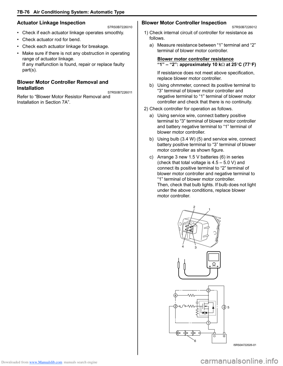
Blower Motor Controller InspectionS7RS0B7226012
1) Check internal circuit of controller for resistance as follows.
a) Measure resistance between “1” terminal and “2” terminal of blower motor controller.
Blower motor cont roller resistance
“1” – “2”: approximately 10 k Ω at 25 °C (77 °F)
If resistance does not meet above specification,
replace blower motor controller.
b) Using ohmmeter, connect its positive terminal to “3” terminal of blower motor controller and
negative terminal to “1” terminal of blower motor
controller and check that there is no continuity.
2) Check controller for operation as follows. a) Using service wire, connect battery positive terminal to “3” terminal of blower motor controller
and battery negative terminal to “1” terminal of
blower motor controller.
b) Using bulb (3.4 W) (5) and service wire, connect battery positive terminal to “3” terminal of blower
motor controller as shown figure.
c) Arrange 3 new 1.5 V batteries (6) in series (check that total voltage is 4.5 – 5.0 V) and
connect its positive term inal to “2” terminal of
blower motor controller and negative terminal to
“1” terminal of blower motor controller.
Then, check that bulb lights. If bulb does not light
under the above conditions, replace blower
motor controller.
3
1
2
4
2
1
3
4
5
6I5RS0A722026-01
Page 1029 of 1496
Downloaded from www.Manualslib.com manuals search engine Table of Contents 8- i
8
Section 8
CONTENTS
Restraint
Precautions ................................................. 8-1
Precautions............................................................. 8-1
Precautions on Restraint ....................................... 8-1
Seat Belts .......... ............................... ........ 8A-1
Precautions........................................................... 8A-1
Precautions on Service a nd Diagnosis of Seat
Belt .................................................................... 8A-1
General Description ............................................. 8A-1 Seat Belt Construction ........................................ 8A-1
Diagnostic Information and Procedures ............ 8A-2 Repair and Inspection Required after Accident ............................................................ 8A-2
Repair Instructions .............................................. 8A-3 Front Seat Belt Components ............................... 8A-3
Front Seat Belt Removal and Installation ............ 8A-4
Front Seat Belt Inspection ................................... 8A-4
Rear Seat Belt Components ............................... 8A-6
Rear Seat Belt Removal and Installation ............ 8A-7
Rear Seat Belt Inspection ................................... 8A-7
Specifications ....................................................... 8A-7
Tightening Torque Specifications ........................ 8A-7
Air Bag System ............... ......................... 8B-1
Precautions........................................................... 8B-1
Precautions on Service and Diagnosis of Air Bag System....................................................... 8B-1
Precautions on Handling and Storage of Air Bag System Components . ................................ 8B-2
Precautions on Disposal of Air Bag and Seat
Belt Pretensioner .............................................. 8B-5
General Description ............................................. 8B-5 Air Bag System Construction .............................. 8B-5
Air Bag System Input / Output Table .................. 8B-6
Schematic and Routing Diagram ........................ 8B-7 Air Bag System Wiring Circuit Diagram .............. 8B-7
Component Locatio n ........................................... 8B-9
Air Bag System Components, Wiring and Connectors Location ......................................... 8B-9
Diagnostic Information and Procedures .......... 8B-10 Air Bag Diagnostic System Check .................... 8B-10
Air Bag Diagnostic System Check Flow ............ 8B-10
DTC Table ......................................................... 8B-11
DTC Check ....................................................... 8B-12 DTC Clearance ................................................. 8B-12
Scan Tool Data ................................................. 8B-13
“AIR BAG” Warning Right Comes ON Steady .. 8B-13
“AIR BAG” Warning Right Does Not Come
ON ................................................................... 8B-15
“AIR BAG” Warning Right Flashes .................... 8B-16
DTC B1013: SDM fault...................................... 8B-17
DTC B1014: “AIR BAG” Warning Right Circuit Failure ............................................................. 8B-17
DTC B1016: Power Source Voltage High ......... 8B-18
DTC B1017: Power Source Voltage Low .......... 8B-20
DTC B1021: Front Air Bag Module Deployed ... 8B-22
DTC B1024 / B1025: Side-Air Bag (Driver / Passenger) Deployed...................................... 8B-22
DTC B1026: Pretensioner Activated ................. 8B-23
DTC B1027: Reusable Number Exceeded ....... 8B-24
DTC B1031: Driver Air Bag Initiator Circuit
Resistance High .............................................. 8B-24
DTC B1032: Driver Air Bag Initiator Circuit
Resistance Low ............................................... 8B-29
DTC B1033: Driver Air Bag Initiator Circuit
Short to Ground............................................... 8B-34
DTC B1034: Driver Air Bag Initiator Circuit
Short to Power Circuit .... ................................. 8B-39
DTC B1041: Passenger Air Bag Initiator Circuit Resistance High ................................... 8B-44
DTC B1042: Passenger Air Bag Initiator Circuit Resistance Low.................................... 8B-47
DTC B1043: Passenger Air Bag Initiator Circuit Short to Ground ................................... 8B-50
DTC B1044: Passenger Air Bag Initiator Circuit Short to Power Circ uit .......................... 8B-53
DTC B1051 / B1055: Driver / Passenger Pretensioner Initiator Circuit Resistance
High ................................................................. 8B-56
DTC B1052 / B1056: Driver / Passenger Pretensioner Initiator Circu it Resistance Low .. 8B-58
DTC B1053 / B1057: Driver / Passenger Pretensioner Initiator Circuit Short to Ground .. 8B-60
DTC B1054 / B1058: Driver / Passenger Pretensioner Initiator Circuit Short to Power
Circuit .............................................................. 8B-62
DTC B1061 / B1065: Driver / Passenger Side- Air Bag Initiator Circuit Resistance High ......... 8B-64