2007 SUZUKI SWIFT washer hose
[x] Cancel search: washer hosePage 529 of 1496

Downloaded from www.Manualslib.com manuals search engine Rear Brakes: 4C-5
4) Pass parking brake cable (1) through bracket (3) of caliper.
5) Hang parking brake cable on lever (2) as follows.
NOTE
Make sure that lever (4) contacts pin (5).
6) Install brake pads and caliper referring to “Rear Disc Brake Pad Removal and Installation”.
7) Connect flexible hose (1) with new washers to caliper (2).
WARNING!
Make sure that flexible hose is not twisted
when tightening joint bolt. If it is twisted,
reconnect it using care not to twist it.
Tightening torque
Flexible hose joint bolt (a): 23 N·m (2.3 kgf-m,
17.0 lb-ft) 8) Install brake cable clip (1) securely to bracket (2).
9) After reassembling brake lines, bleed air from them
referring to “Air Bleeding of Brake System in Section
4A”.
10) Check to make sure that system is free from fluid
leakage.
11) Start engine and then depress brake pedal with about 300 N (30 kg, 66 lbs) load 3 times or more so
as to obtain proper disc to pad clearance.
12) Check to make sure that parking brake lever stroke is as specified. Refer to “Parking Brake Inspection
and Adjustment in Section 4D”.
13) Tighten wheel nuts to specified torque.
Tightening torque
Wheel bolt: 85 N·m (8.5 kgf-m, 61.5 lb-ft)
14) Remove vehicle from hoist and perform brake test (foot brake and parking brake).
1
23
45
I6RS0C430010-01
1 (a)2
I6RS0C430011-01
1
2
I6RS0C430012-01
Page 753 of 1496
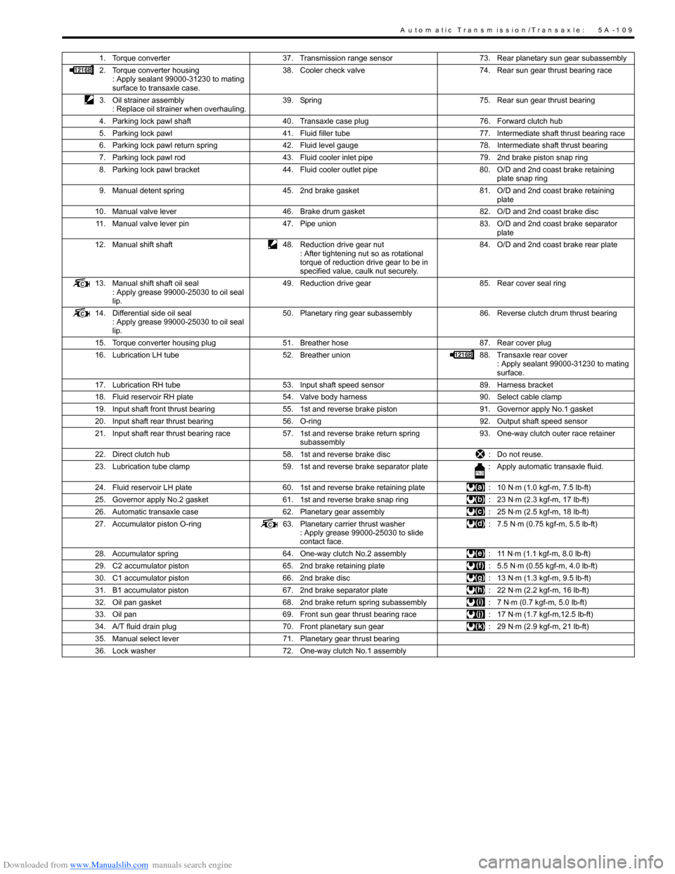
Downloaded from www.Manualslib.com manuals search engine A u to m a tic Tra n s m is s io n /Tra n s a x le : 5 A -1 0 9
1. Torque converter37. Transmission range sensor 73. Rear planetary sun gear subassembly
2. Torque converter housing : Apply sealant 99000-31230 to mating
surface to transaxle case. 38. Cooler check valve
74. Rear sun gear thrust bearing race
3. Oil strainer assembly : Replace oil strainer when overhauling. 39. Spring
75. Rear sun gear thrust bearing
4. Parking lock pawl shaft 40. Transaxle case plug 76. Forward clutch hub
5. Parking lock pawl 41. Fluid filler tube 77. Intermediate shaft thrust bearing race
6. Parking lock pawl return spring 42. Fluid level gauge 78. Intermediate shaft thrust bearing
7. Parking lock pawl rod 43. Fluid cooler inlet pipe 79. 2nd brake piston snap ring
8. Parking lock pawl bracket 44. Fluid cooler outlet pipe 80. O/D and 2nd coast brake retaining
plate snap ring
9. Manual detent spring 45. 2nd brake gasket 81. O/D and 2nd coast brake retaining
plate
10. Manual valve lever 46. Brake drum gasket 82. O/D and 2nd coast brake disc
11. Manual valve lever pin 47. Pipe union 83. O/D and 2nd coast brake separator
plate
12. Manual shift shaft 48. Reduction drive gear nut
: After tightening nut so as rotational
torque of reduction drive gear to be in
specified value, caulk nut securely. 84. O/D and 2nd coast brake rear plate
13. Manual shift shaft oil seal : Apply grease 99000-25030 to oil seal
lip. 49. Reduction drive gear
85. Rear cover seal ring
14. Differential side oil seal : Apply grease 99000-25030 to oil seal
lip. 50. Planetary ring gear subassembly
86. Reverse clutch drum thrust bearing
15. Torque converter housing plug 51. Breather hose 87. Rear cover plug
16. Lubrication LH tube 52. Breather union 88. Transaxle rear cover
: Apply sealant 99000-31230 to mating
surface.
17. Lubrication RH tube 53. Input shaft speed sensor 89. Harness bracket
18. Fluid reservoir RH plate 54. Valve body harness 90. Select cable clamp
19. Input shaft front thrust bearing 55. 1st and reverse brake piston 91. Governor apply No.1 gasket
20. Input shaft rear thrust bearing 56. O-ring 92. Output shaft speed sensor
21. Input shaft rear thrust bearing race 57. 1st and reverse brake return spring
subassembly 93. One-way clutch outer race retainer
22. Direct clutch hub 58. 1st and reverse brake disc : Do not reuse.
23. Lubrication tube clamp 59. 1st and reverse brake separator plate : Apply automatic transaxle fluid.
24. Fluid reservoir LH plate 60. 1st and reverse brake retaining plate : 10 N⋅m (1.0 kgf-m, 7.5 lb-ft)
25. Governor apply No.2 gasket 61. 1st and reverse brake snap ring : 23 N⋅m (2.3 kgf-m, 17 lb-ft)
26. Automatic transaxle case 62. Planetary gear assembly : 25 N⋅m (2.5 kgf-m, 18 lb-ft)
27. Accumulator piston O-ring 63. Planetary carrier thrust washer
: Apply grease 99000-25030 to slide
contact face. : 7.5 N
⋅m (0.75 kgf-m, 5.5 lb-ft)
28. Accumulator spring 64. One-way clutch No.2 assembly : 11 N⋅m (1.1 kgf-m, 8.0 lb-ft)
29. C2 accumulator piston 65. 2nd brake retaining plate : 5.5 N⋅m (0.55 kgf-m, 4.0 lb-ft)
30. C1 accumulator piston 66. 2nd brake disc : 13 N⋅m (1.3 kgf-m, 9.5 lb-ft)
31. B1 accumulator piston 67. 2nd brake separator plate : 22 N⋅m (2.2 kgf-m, 16 lb-ft)
32. Oil pan gasket 68. 2nd brake return spring subassembly : 7 N⋅m (0.7 kgf-m, 5.0 lb-ft)
33. Oil pan 69. Front sun gear thrust bearing race : 17 N⋅m (1.7 kgf-m,12.5 lb-ft)
34. A/T fluid drain plug 70. Front planetary sun gear : 29 N⋅m (2.9 kgf-m, 21 lb-ft)
35. Manual select lever 71. Planetary gear thrust bearing
36. Lock washer 72. One-way clutch No.1 assembly
Page 828 of 1496

Downloaded from www.Manualslib.com manuals search engine 5B-14 Manual Transmission/Transaxle:
Fifth Gear Disassembly and AssemblyS7RS0B5206014
Disassembly1) Remove cover bolts and take off transaxle side cover (1).
CAUTION!
Care should be taken not to distort side cover
when it is removed from left case.
2) Using snap ring pliers, remove circlip (1).
3) Remove 5th shift fork bolt (2).
4) Remove gear shift fork (3), synchronizer sleeve &
hub assembly (4), synchron izer levers, synchronizer
ring and input shaft 5th gear (5) all together. Use
gear puller for removal if spline fitting of hub is tight. 5) Unfasten caulking of countershaft nut (2), install
input shaft 5th gear (1) and special tool to stop
rotation of shafts, and then remove countershaft nut
(2).
Special tool
(A): 09927–76060
6) Remove input shaft 5th gear, needle bearing and then countershaft 5th gear (1). Gear puller (2) would
be necessary if spline fitting of countershaft 5th gear
is tight.
11. Sensor cap 34. Washer
12. Oil gutter bolt : Apply thread lock 99000-32110 to all around thread part of bolt. 35. Side bearing retainer
13. Left case plate bolts : Apply thread lock 99000-32110 to all around thread part of bolt. 36. O-ring
14. Sensor cap bolt 37. Oil seal
: Apply grease 99000-25011 to oil seal lip.
15. Side cover bolts 38. Outer race
16. Transaxle case bolts 39. Breather hose
17. 5th speed synchronizer ring 40. Side bearing retainer bolt
18. 5th speed synchronizer lever : 23 N⋅m (2.3 kgf-m, 17.0 lb-ft)
19. 5th speed synchronizer sleeve & hub : 21 N⋅m (2.1 kgf-m, 15.5 lb-ft)
20. Circlip :10 N⋅m (1.0 kgf-m, 7.5 lb-ft)
21. Bearing set shim : 100 N⋅m (10.0 kgf-m, 72.5 lb-ft)
22. Countershaft 5th gear : Do not reuse.
23. Countershaft nut : After tightening nut to specified torque, caulk nut securely. : Apply transaxle oil.
I4RS0A520027-01
342
1
5
I4RS0A520028-01
1(A)
2
I3RM0B521014-01
I4RS0A520041-01
Page 1318 of 1496
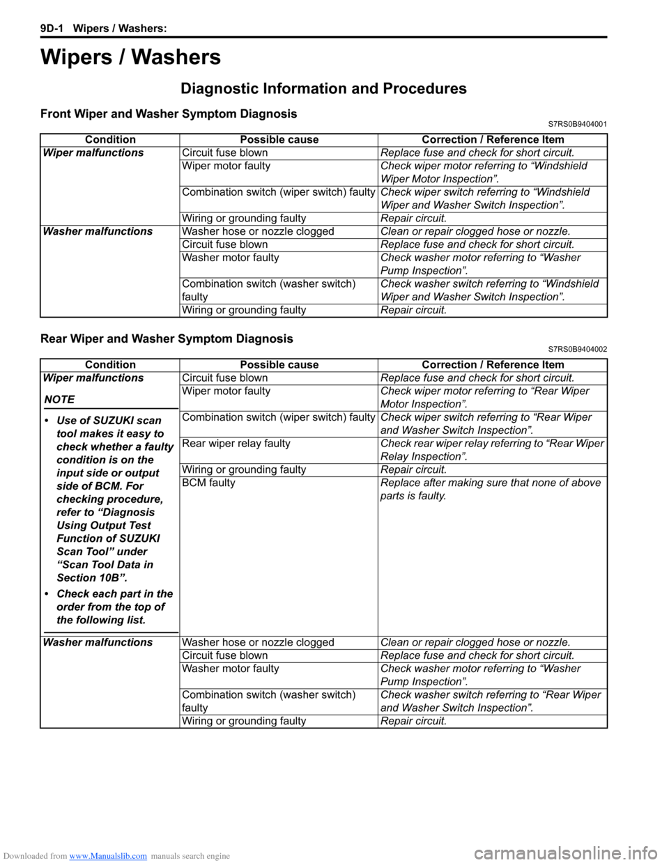
Downloaded from www.Manualslib.com manuals search engine 9D-1 Wipers / Washers:
Body, Cab and Accessories
Wipers / Washers
Diagnostic Information and Procedures
Front Wiper and Washer Symptom DiagnosisS7RS0B9404001
Rear Wiper and Washer Symptom DiagnosisS7RS0B9404002
ConditionPossible cause Correction / Reference Item
Wiper malfunctions Circuit fuse blown Replace fuse and check for short circuit.
Wiper motor faulty Check wiper motor referring to “Windshield
Wiper Motor Inspection”.
Combination switch (wiper switch) faulty Check wiper switch referring to “Windshield
Wiper and Washer Switch Inspection”.
Wiring or grounding faulty Repair circuit.
Washer malfunctions Washer hose or nozzle clogged Clean or repair clogged hose or nozzle.
Circuit fuse blown Replace fuse and check for short circuit.
Washer motor faulty Check washer motor referring to “Washer
Pump Inspection”.
Combination switch (washer switch)
faulty Check washer switch referring to “Windshield
Wiper and Washer Switch Inspection”.
Wiring or grounding faulty Repair circuit.
ConditionPossible cause Correction / Reference Item
Wiper malfunctions
NOTE
• Use of SUZUKI scan tool makes it easy to
check whether a faulty
condition is on the
input side or output
side of BCM. For
checking procedure,
refer to “Diagnosis
Using Output Test
Function of SUZUKI
Scan Tool” under
“Scan Tool Data in
Section 10B”.
• Check each part in the order from the top of
the following list.
Circuit fuse blown Replace fuse and check for short circuit.
Wiper motor faulty Check wiper motor referring to “Rear Wiper
Motor Inspection”.
Combination switch (wiper switch) faulty Check wiper switch referring to “Rear Wiper
and Washer Switch Inspection”.
Rear wiper relay faulty Check rear wiper relay referring to “Rear Wiper
Relay Inspection”.
Wiring or grounding faulty Repair circuit.
BCM faulty Replace after making sure that none of above
parts is faulty.
Washer malfunctions Washer hose or nozzle clogged Clean or repair clogged hose or nozzle.
Circuit fuse blown Replace fuse and check for short circuit.
Washer motor faulty Check washer motor referring to “Washer
Pump Inspection”.
Combination switch (washer switch)
faulty Check washer switch referring to “Rear Wiper
and Washer Switch Inspection”.
Wiring or grounding faulty Repair circuit.
Page 1320 of 1496
Downloaded from www.Manualslib.com manuals search engine 9D-3 Wipers / Washers:
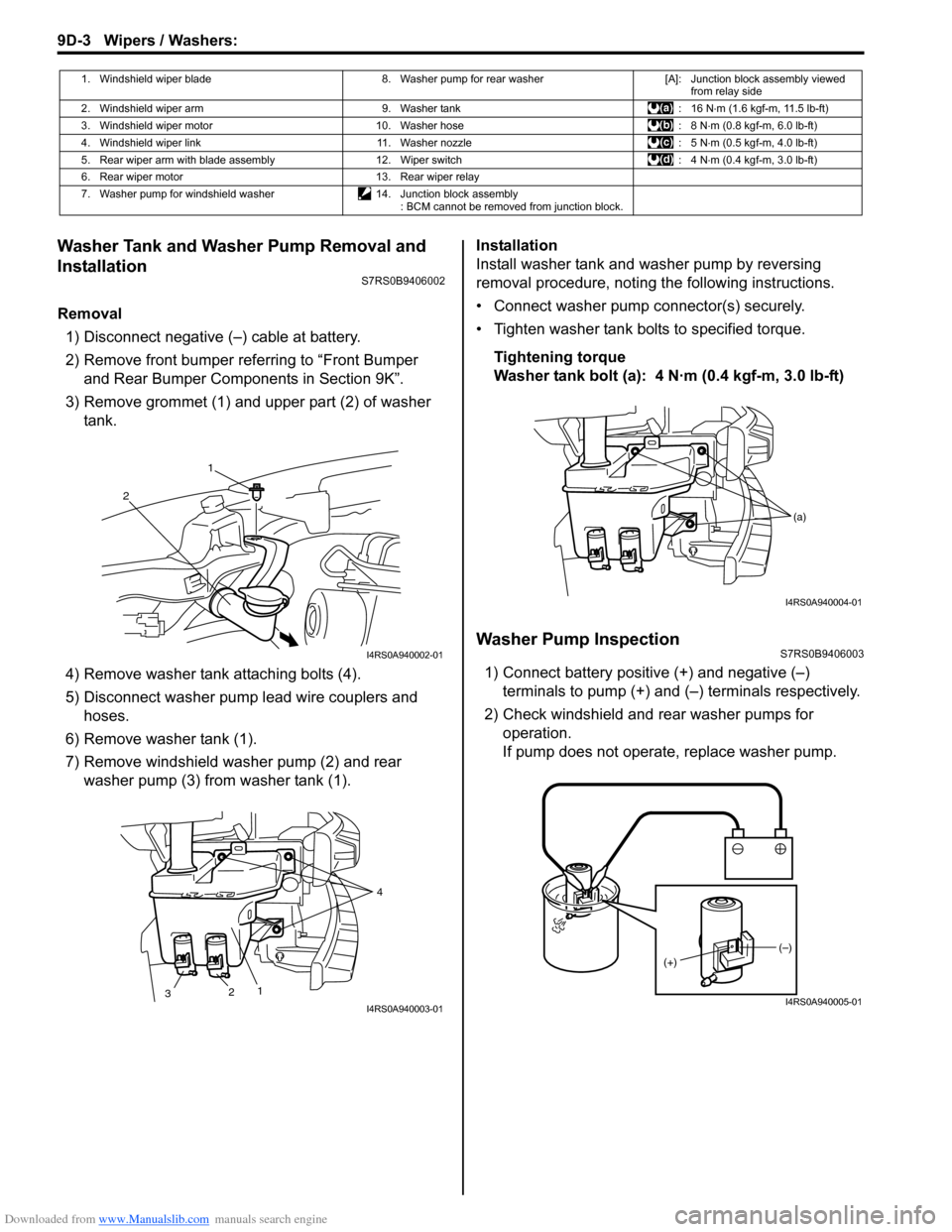
Washer Tank and Washer Pump Removal and
Installation
S7RS0B9406002
Removal1) Disconnect negative (–) cable at battery.
2) Remove front bumper referring to “Front Bumper and Rear Bumper Components in Section 9K”.
3) Remove grommet (1) and upper part (2) of washer tank.
4) Remove washer tank attaching bolts (4).
5) Disconnect washer pump lead wire couplers and hoses.
6) Remove washer tank (1).
7) Remove windshield washer pump (2) and rear washer pump (3) from washer tank (1). Installation
Install washer tank and washer pump by reversing
removal procedure, noting the following instructions.
• Connect washer pump connector(s) securely.
• Tighten washer tank bolts to specified torque.
Tightening torque
Washer tank bolt (a): 4 N·m (0.4 kgf-m, 3.0 lb-ft)
Washer Pump InspectionS7RS0B9406003
1) Connect battery positive (+) and negative (–) terminals to pump (+) and (–) terminals respectively.
2) Check windshield and rear washer pumps for
operation.
If pump does not operate, replace washer pump.
1. Windshield wiper blade 8. Washer pump for rear washer[A]: Junction block assembly viewed
from relay side
2. Windshield wiper arm 9. Washer tank: 16 N⋅m (1.6 kgf-m, 11.5 lb-ft)
3. Windshield wiper motor 10. Washer hose : 8 N⋅m (0.8 kgf-m, 6.0 lb-ft)
4. Windshield wiper link 11. Washer nozzle : 5 N⋅m (0.5 kgf-m, 4.0 lb-ft)
5. Rear wiper arm with blade assembly 12. Wiper switch : 4 N⋅m (0.4 kgf-m, 3.0 lb-ft)
6. Rear wiper motor 13. Rear wiper relay
7. Washer pump for windshield washer 14. Junction block assembly
: BCM cannot be removed from junction block.
1
2
I4RS0A940002-01
2 1 4
3
I4RS0A940003-01
(a)
I4RS0A940004-01
(–)
(+)
I4RS0A940005-01
Page 1370 of 1496
Downloaded from www.Manualslib.com manuals search engine 9J-1 Hood / Fenders / Doors:
Body, Cab and Accessories
Hood / Fenders / Doors
Repair Instructions
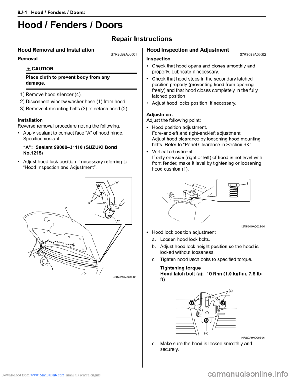
Hood Removal and InstallationS7RS0B9A06001
Removal
CAUTION!
Place cloth to prevent body from any
damage.
1) Remove hood silencer (4).
2) Disconnect window washer hose (1) from hood.
3) Remove 4 mounting bolts (3) to detach hood (2).
Installation
Reverse removal procedure noting the following.
• Apply sealant to contact face “A” of hood hinge. Specified sealant.
“A”: Sealant 99000–31110 (SUZUKI Bond
No.1215)
• Adjust hood lock position if necessary referring to “Hood Inspection and Adjustment”.
Hood Inspection and AdjustmentS7RS0B9A06002
Inspection
• Check that hood opens and closes smoothly and properly. Lubricate if necessary.
• Check that hood stops in the secondary latched position properly (preventing hood from opening
freely) and that hood closes completely in the fully
latched position.
• Adjust hood locks position, if necessary.
Adjustment
Adjust the following point:
• Hood position adjustment. Fore-and-aft and right-and-left adjustment.
Adjust hood clearance by loosening hood mounting
bolts. Refer to “Panel Clearance in Section 9K”.
• Vertical adjustment If only one side (right or left) of hood is not level with
front fender, make it level by tightening or loosening
hood cushion (1).
• Hood lock position adjustment a. Loosen hood lock bolts.
b. Adjust hood lock height position so the hood is locked without looseness.
c. Tighten hood latch bolts to specified torque.
Tightening torque
Hood latch bolt (a): 10 N·m (1.0 kgf-m, 7.5 lb-
ft)
d. Make sure the hood is locked smoothly and securely.
“A”
“A”
3
2
4
1
I4RS0A9A0001-01
I2RH019A0022-01
(a)
(a)I4RS0A9A0002-01
Page 1375 of 1496
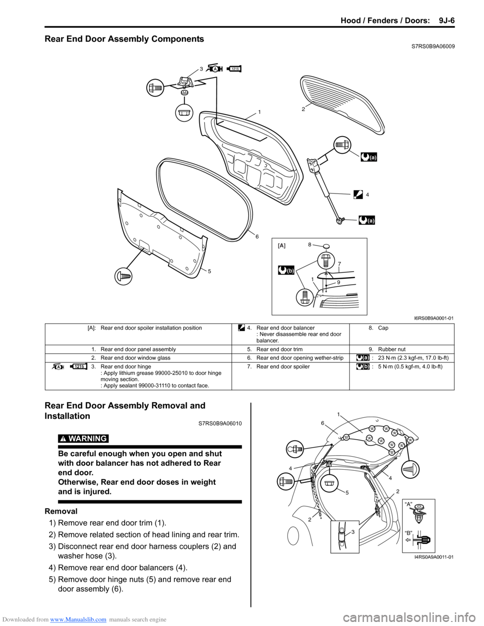
Downloaded from www.Manualslib.com manuals search engine Hood / Fenders / Doors: 9J-6
Rear End Door Assembly ComponentsS7RS0B9A06009
Rear End Door Assembly Removal and
Installation
S7RS0B9A06010
WARNING!
Be careful enough when you open and shut
with door balancer has not adhered to Rear
end door.
Otherwise, Rear end door doses in weight
and is injured.
Removal1) Remove rear end door trim (1).
2) Remove related section of head lining and rear trim.
3) Disconnect rear end door harness couplers (2) and washer hose (3).
4) Remove rear end door balancers (4).
5) Remove door hinge nuts (5) and remove rear end door assembly (6).
3
(a)
(a)
12
6
5
[A]
1
7
9
8
(b)
4
I6RS0B9A0001-01
[A]: Rear end door spoiler installation position 4. Rear end door balancer
: Never disassemble rear end door
balancer. 8. Cap
1. Rear end door panel assembly 5. Rear end door trim9. Rubber nut
2. Rear end door window glass 6. Rear end door opening wether-strip: 23 N⋅m (2.3 kgf-m, 17.0 lb-ft)
3. Rear end door hinge : Apply lithium grease 99000-25010 to door hinge
moving section.
: Apply sealant 99000-31110 to contact face. 7. Rear end door spoiler
: 5 N⋅m (0.5 kgf-m, 4.0 lb-ft)
“A”
“B”
“B”
“A”“B”“A”“A”“A”
“A”“A”“A”
“A”
1
6
5 4
2
3
2
4
I4RS0A9A0011-01