2007 SUZUKI SWIFT engine coolant temp. sensor
[x] Cancel search: engine coolant temp. sensorPage 131 of 1496
Downloaded from www.Manualslib.com manuals search engine Engine General Information and Diagnosis: 1A-81
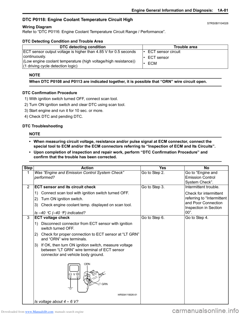
DTC P0118: Engine Coolant Temperature Circuit HighS7RS0B1104028
Wiring Diagram
Refer to “DTC P0116: Engine Coolant Temperature Circuit Range / Performance”.
DTC Detecting Condition and Trouble Area
NOTE
When DTC P0108 and P0113 are indicated together, it is possible that “ORN” wire circuit open.
DTC Confirmation Procedure
1) With ignition switch turned OFF, connect scan tool.
2) Turn ON ignition switch and clear DTC using scan tool.
3) Start engine and run it for 10 sec. or more.
4) Check DTC and pending DTC.
DTC Troubleshooting
NOTE
• When measuring circuit voltage, resistance and/ or pulse signal at ECM connector, connect the
special tool to ECM and/or the ECM connectors re ferring to “Inspection of ECM and Its Circuits”.
• Upon completion of inspection and repair work, perform “DTC Confirmation Procedure” and confirm that the trouble has been corrected.
DTC detecting condition Trouble area
ECT sensor output voltage is higher than 4.85 V for 0.5 seconds
continuously.
(Low engine coolant temperature (high voltage/high resistance))
(1 driving cycle detection logic) • ECT sensor circuit
• ECT sensor
•ECM
Step
Action YesNo
1 Was “Engine and Emission Control System Check”
performed? Go to Step 2.
Go to “Engine and
Emission Control
System Check”.
2 ECT sensor and its circuit check
1) Connect scan tool with i gnition switch turned OFF.
2) Turn ON ignition switch.
3) Check engine coolant temp. displayed on scan tool.
Is –40
°C (–40 °F) indicated? Go to Step 3. Intermittent trouble.
Check for intermittent
referring to “Intermittent
and Poor Connection
Inspection in Section
00”.
3 ECT voltage check
1) Disconnect connector from ECT sensor with ignition
switch turned OFF.
2) Check for proper connection to ECT sensor at “LT GRN” and “ORN” wire terminals.
3) If OK, then turn ON igniti on switch, measure voltage
between “LT GRN” wire terminal of ECT sensor
connector and vehicle body ground.
Is voltage about 4 – 6 V? Go to Step 6. Go to Step 4.
I4RS0A110026-01
Page 155 of 1496
Downloaded from www.Manualslib.com manuals search engine Engine General Information and Diagnosis: 1A-105
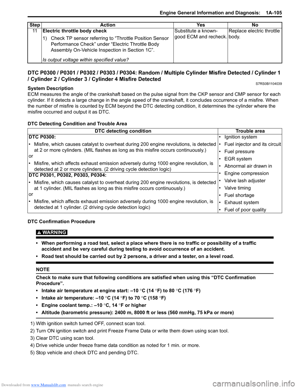
DTC P0300 / P0301 / P0302 / P0303 / P0304: Random / Multiple Cylinder Misfire Detected / Cylinder 1
/ Cylinder 2 / Cylinder 3 / Cylinder 4 Misfire Detected
S7RS0B1104039
System Description
ECM measures the angle of the crankshaft based on the pulse signal from the CKP sensor and CMP sensor for each
cylinder. If it detects a large change in the angle speed of the crankshaft, it concludes occurrence of a misfire. When
the number of misfire is counted by ECM beyond the DTC de tecting condition, it determines the cylinder where the
misfire occurred and output it as DTC.
DTC Detecting Condition and Trouble Area
DTC Confirmation Procedure
WARNING!
• When performing a road test, select a place where there is no traffic or possibility of a traffic accident and be very careful during testing to avoid occurrence of an accident.
• Road test should be carried out by 2 persons, a driver and a tester, on a level road.
NOTE
Check to make sure that following conditions ar e satisfied when using this “DTC Confirmation
Procedure”.
• Intake air temperature at engine start: –10 °C (14 ° F) to 80 °C (176 °F)
• Intake air temperature: –10 °C (14 °F) to 70 °C (158 °F)
• Engine coolant temp.: –10 °C, 14 °F or higher
• Altitude (barometric pressure): 2400 m, 8000 ft or less (560 mmHg, 75 kPa or more)
1) With ignition switch turned OFF, connect scan tool.
2) Turn ON ignition switch and print Freeze Frame Data or write them down using scan tool.
3) Clear DTC using scan tool.
4) Drive vehicle under freeze frame data condition as noted for 1 min. or more.
5) Stop vehicle and check DTC and pending DTC. 11
Electric throttle body check
1) Check TP sensor referring to “Throttle Position Sensor
Performance Check” under “Electric Throttle Body
Assembly On-Vehicle Inspection in Section 1C”.
Is output voltage within specified value? Substitute a known-
good ECM and recheck.
Replace electric throttle
body.
Step Action Yes No
DTC detecting condition
Trouble area
DTC P0300:
• Misfire, which causes catalyst to overheat during 200 engine revolutions, is detected at 2 or more cylinders. (MIL flashes as lo ng as this misfire occurs continuously.)
or
• Misfire, which affects exhaust emission adv ersely during 1000 engine revolution, is
detected at 2 or more cylinders. (2 driving cycle detection logic) • Ignition system
• Fuel injector and its circuit
• Fuel pressure
• EGR system
• Abnormal air drawn in
• Engine compression
• Valve lash adjuster
• Valve timing
• Fuel shortage
• Exhaust system
• Fuel of poor quality
DTC P0301, P0302, P0303, P0304:
• Misfire, which causes catalyst to overheat during 200 engine revolutions, is detected
at 1 cylinder. (MIL flashes as long as this misfire occurs continuously.)
or
• Misfire, which affects exhaust emission adv ersely during 1000 engine revolution, is
detected at 1 cylinder. (2 driving cycle detection logic)
Page 233 of 1496
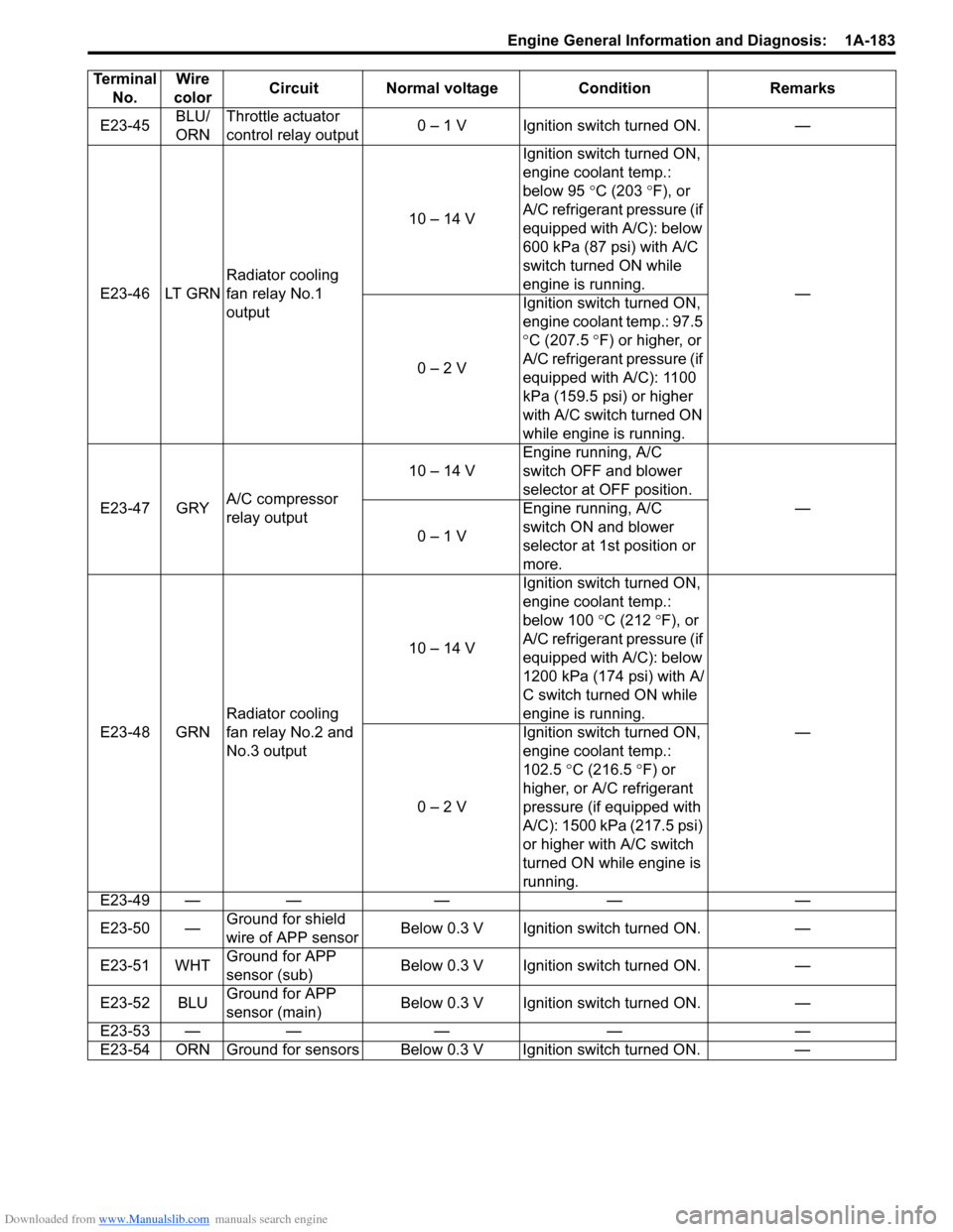
Downloaded from www.Manualslib.com manuals search engine Engine General Information and Diagnosis: 1A-183
E23-45BLU/
ORNThrottle actuator
control relay output
0 – 1 V Ignition switch turned ON. —
E23-46 LT GRN Radiator cooling
fan relay No.1
output 10 – 14 V
Ignition switch turned ON,
engine coolant temp.:
below 95
°C (203 ° F), or
A/C refrigerant pressure (if
equipped with A/C): below
600 kPa (87 psi) with A/C
switch turned ON while
engine is running. —
0 – 2 V Ignition switch turned ON,
engine coolant temp.: 97.5
°
C (207.5 ° F) or higher, or
A/C refrigerant pressure (if
equipped with A/C): 1100
kPa (159.5 psi) or higher
with A/C switch turned ON
while engine is running.
E23-47 GRY A/C compressor
relay output 10 – 14 V
Engine running, A/C
switch OFF and blower
selector at OFF position.
—
0 – 1 V Engine running, A/C
switch ON and blower
selector at 1st position or
more.
E23-48 GRN Radiator cooling
fan relay No.2 and
No.3 output 10 – 14 V
Ignition switch turned ON,
engine coolant temp.:
below 100
°C (212 °F), or
A/C refrigerant pressure (if
equipped with A/C): below
1200 kPa (174 psi) with A/
C switch turned ON while
engine is running. —
0 – 2 V Ignition switch turned ON,
engine coolant temp.:
102.5
°C (216.5 °F) or
higher, or A/C refrigerant
pressure (if equipped with
A/C): 1500 kPa (217.5 psi)
or higher with A/C switch
turned ON while engine is
running.
E23-49 — — — — —
E23-50 — Ground for shield
wire of APP sensor Below 0.3 V Ignition switch turned ON. —
E23-51 WHT Ground for APP
sensor (sub) Below 0.3 V Ignition switch turned ON. —
E23-52 BLU Ground for APP
sensor (main) Below 0.3 V Ignition switch turned ON. —
E23-53 — — — — —
E23-54 ORN Ground for sensors Below 0.3 V Ignition switch turned ON. —
Terminal
No. Wire
color Circuit Normal voltage Condition Remarks
Page 262 of 1496
Downloaded from www.Manualslib.com manuals search engine 1A-212 Engine General Information and Diagnosis:
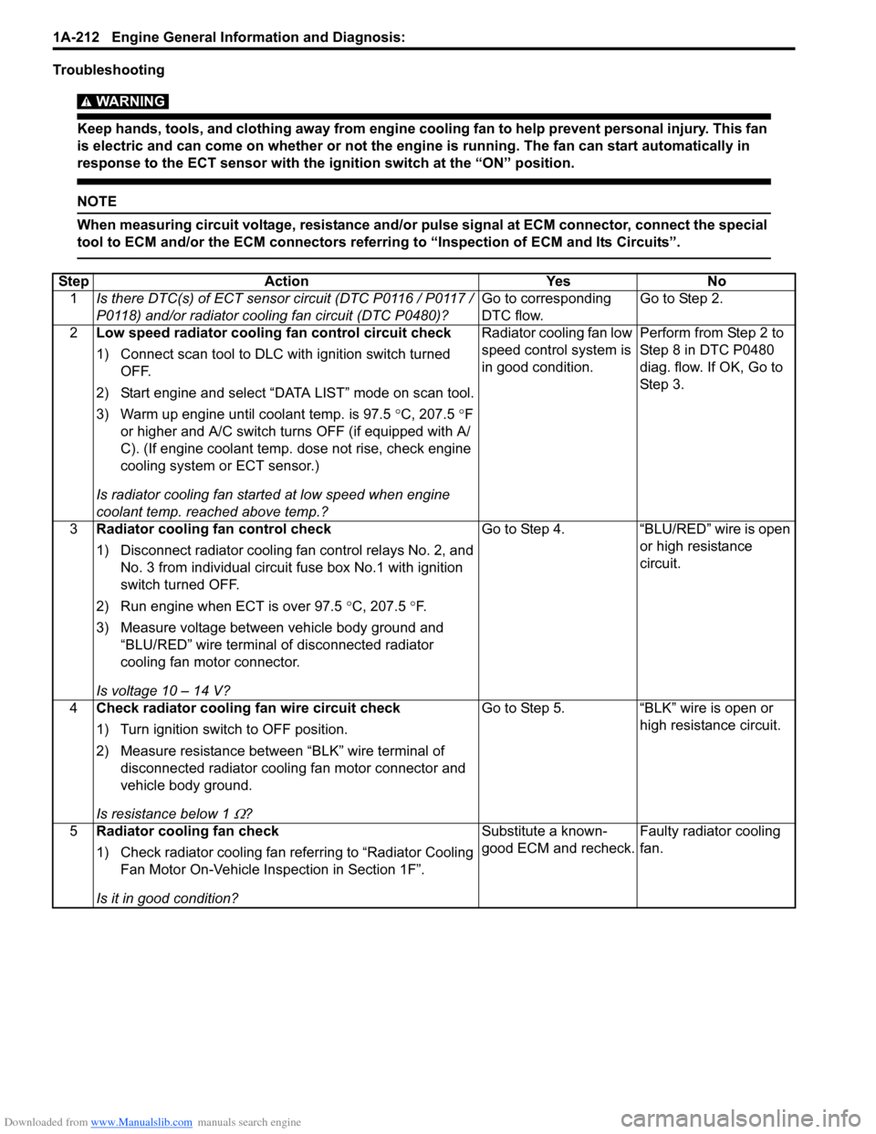
Troubleshooting
WARNING!
Keep hands, tools, and clothing away from engine cooling fan to help prevent personal injury. This fan
is electric and can come on whether or not the engi ne is running. The fan can start automatically in
response to the ECT sensor with the ig nition switch at the “ON” position.
NOTE
When measuring circuit voltage, resistance and/or pulse signal at ECM connector, connect the special
tool to ECM and/or the ECM connectors referri ng to “Inspection of ECM and Its Circuits”.
StepAction YesNo
1 Is there DTC(s) of ECT sensor circuit (DTC P0116 / P0117 /
P0118) and/or radiator cooling fan circuit (DTC P0480)? Go to corresponding
DTC flow.Go to Step 2.
2 Low speed radiator cooling fan control circuit check
1) Connect scan tool to DLC with ignition switch turned
OFF.
2) Start engine and select “DATA LIST” mode on scan tool.
3) Warm up engine until coolant temp. is 97.5 °C, 207.5 °F
or higher and A/C switch turns OFF (if equipped with A/
C). (If engine coolant temp. dose not rise, check engine
cooling system or ECT sensor.)
Is radiator cooling fan started at low speed when engine
coolant temp. reached above temp.? Radiator cooling fan low
speed control system is
in good condition.
Perform from Step 2 to
Step 8 in DTC P0480
diag. flow. If OK, Go to
Ste p 3.
3 Radiator cooling fan control check
1) Disconnect radiator cooling fan control relays No. 2, and
No. 3 from individual circuit fuse box No.1 with ignition
switch turned OFF.
2) Run engine when ECT is over 97.5 °C, 207.5 °F.
3) Measure voltage between vehicle body ground and “BLU/RED” wire terminal of disconnected radiator
cooling fan motor connector.
Is voltage 10 – 14 V? Go to Step 4.
“BLU/RED” wire is open
or high resistance
circuit.
4 Check radiator cooling fan wire circuit check
1) Turn ignition switch to OFF position.
2) Measure resistance between “BLK” wire terminal of
disconnected radiator coolin g fan motor connector and
vehicle body ground.
Is resistance below 1
Ω? Go to Step 5. “BLK” wire is open or
high resistance circuit.
5 Radiator cooling fan check
1) Check radiator cooling fan referring to “Radiator Cooling
Fan Motor On-Vehicle Inspection in Section 1F”.
Is it in good condition? Substitute a known-
good ECM and recheck.
Faulty radiator cooling
fan.
Page 264 of 1496

Downloaded from www.Manualslib.com manuals search engine 1A-214 Engine General Information and Diagnosis:
Troubleshooting
WARNING!
Keep hands, tools, and clothing away from engine cooling fan to help prevent personal injury. This fan
is electric and can come on whether or not the engi ne is running. The fan can start automatically in
response to the ECT sensor with the ig nition switch at the “ON” position.
NOTE
When measuring circuit voltage, resistance and/or pulse signal at ECM connector, connect the special
tool to ECM and/or the ECM connectors referri ng to “Inspection of ECM and Its Circuits”.
StepAction YesNo
1 Is there DTC(s) of ECT sensor circuit (DTC P0116 / P0117 /
P0118) and/or radiator cooling fan circuit (DTC P0480)? Go to corresponding
DTC flow.Go to Step 2.
2 Low speed radiator cooling fan control circuit check
1) Connect scan tool to DLC with ignition switch turned
OFF.
2) Start engine and select “DATA LIST” mode on scan tool.
3) Warm up engine until coolant temp. is 97.5 °C, 207.5 °F
or higher and A/C switch turns OFF (if equipped with A/
C). (If engine coolant temp. dose not rise, check engine
cooling system or ECT sensor.)
Is radiator cooling fan started at low speed when engine
coolant temp. reached above temp.? Go to Step 3.
Perform from Step 2 to
Step 5 in “Radiator
Cooling Fan Low Speed
Control System Check”.
3 High speed radiator cooling fan control circuit check
1) Start engine and select “DATA LIST” mode on scan tool.
2) Warm up engine until coolant temp. is 102.5 °C, 216.5 °F
or higher and A/C switch turns OFF (if equipped with A/
C). (If engine coolant temp. dose not rise, check engine
cooling system or ECT sensor.)
Is radiator cooling fan started at high speed when engine
coolant temp. reached above temp? Radiator cooling fan
control system is in
good condition.
Perform from Step 9 to
Step 14 in DTC P0480
diag. flow.
If OK, Go to Step 4.
4 Radiator cooling fan control No. 2 and No. 3 check
1) Run engine when ECT is over 102.5 °C, 216.5 °F.
2) Measure voltage between vehicle body ground and “E23-48” terminal of ECM connector.
Is voltage lower than 1.5 V? Go to Step 5.
Faulty ECM.
5 Radiator cooling fan No. 2 wire circuit check
1) Remove radiator cooling fan control relay No.2 with
ignition switch turned OFF.
2) Measure voltage between “GRY” wire terminal of disconnected radiator cooling fan control relay No. 2
connector and vehicle body ground.
Is voltage 10 – 14 V? Go to Step 6.
“GRY” wire is open or
high resistance circuit.
6 Radiator cooling fan No. 2 wire circuit check
1) Disconnect connector from radiator cooling fan motor
with ignition swit ch turned OFF.
2) Measure resistance between “BLU/BLK” wire terminal of disconnected radiator cooling fan control relay No. 2
connector and vehicle body ground.
Is resistance infinity? Go to Step 7.
“BLU/BLK” wire is
shorted to ground
circuit.
Page 658 of 1496
Downloaded from www.Manualslib.com manuals search engine 5A-14 Automatic Transmission/Transaxle:
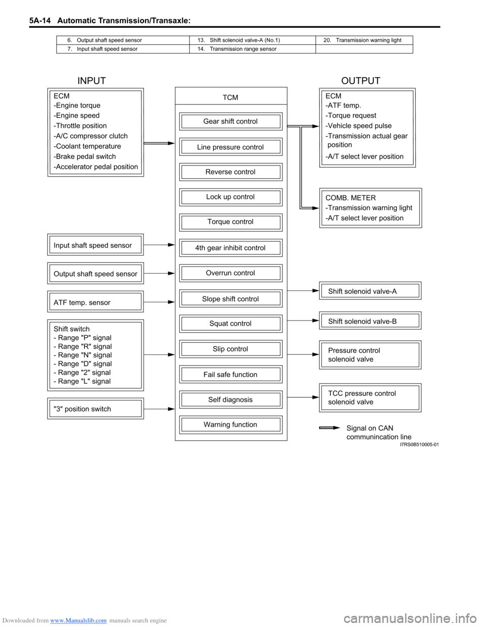
6. Output shaft speed sensor 13. Shift solenoid valve-A (No.1) 20. Transmission warning light
7. Input shaft speed sensor 14. Transmission range sensor
INPUT OUTPUT
TCMECM
Gear shift control
4th gear inhibit control
Slope shift control
Slip control
Lock up control
Torque control
Line pressure control
Overrun control
Reverse control
Squat control
Input shaft speed sensor
Output shaft speed sensor
"3" position switch ATF temp. sensor
Shift switch
- Range "P" signal
- Range "R" signal
- Range "N" signal
- Range "D" signal
- Range "2" signal
- Range "L" signal
Fail safe function
Self diagnosis
Warning function
ECM
Shift solenoid valve-A
Shift solenoid valve-B
TCC pressure control
solenoid valve
Pressure control
solenoid valve
Signal on CAN
communincation line
COMB. METER
-Engine torque
-Engine speed
-Throttle position
-A/C compressor clutch
-Coolant temperature
-Brake pedal switch -ATF temp.
-Torque request
-Vehicle speed pulse
-Transmission actual gear
position
-A/T select lever position
-Accelerator pedal position
-Transmission warning light
-A/T select lever position
I7RS0B510005-01
Page 1019 of 1496
Downloaded from www.Manualslib.com manuals search engine Air Conditioning System: Automatic Type 7B-71
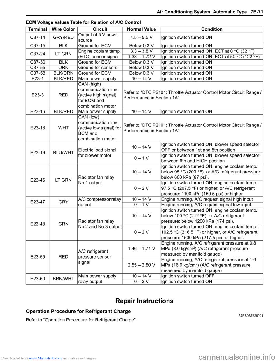
ECM Voltage Values Table for Relation of A/C Control
Repair Instructions
Operation Procedure for Refrigerant ChargeS7RS0B7226001
Refer to “Operation Procedure for Refrigerant Charge”.Terminal Wire Color Circuit Normal Value Condition
C37-14 GRY/RED Output of 5 V power
source 4.5 – 5.5 V Ignition switch turned ON
C37-15 BLK Ground for ECM Below 0.3 V Ignition switch turned ON
C37-24 LT GRN Engine coolant temp.
(ETC) sensor signal 3.3 – 3.8 V Ignition switch turned ON, ECT at 0
°C (32 ° F)
1.38 – 1.72 V Ignition switch turned ON, ECT at 50 °C (122 °F)
C37-30 BLK Ground for ECM Below 0.3 V Ignition switch turned ON
C37-55 ORN Ground for sensors Below 0.3 V Ignition switch turned ON
C37-58 BLK/ORN Ground for ECM Below 0.3 V Ignition switch turned ON E23-1 BLK/RED Main power supply 10 – 14 V Ignition switch turned ON
E23-3 RED CAN (high)
communication line
(active high signal)
for BCM and
combination meterRefer to “DTC P2101: Throttle Actu
ator Control Motor Circuit Range /
Performance in Section 1A”
E23-16 BLK/RED Main power supply 10 – 14 V Ignition switch turned ON
E23-18 WHT CAN (low)
communication line
(active low signal) for
BCM and
combination meterRefer to “DTC P2101: Throttle Actu
ator Control Motor Circuit Range /
Performance in Section 1A”
E23-19 BLU/WHT Electric load signal
for blower motor 10 – 14 V
Ignition switch turned ON, blower speed selector
OFF or between 1st and 5th position
0 – 1 V Ignition switch turned ON, blower speed selector
between 6th and HIGH position
E23-46 LT GRN Radiator fan relay
No.1 output 10 – 14 V
Ignition switch turned ON, engine coolant temp.:
below 95
°C (203 ° F), or A/C refrigerant pressure:
below 600 kPa (87 psi).
0 – 2 V Ignition switch turned ON, engine coolant temp.:
97.5
°C (207.5 °F) or higher, or A/C refrigerant
pressure: 1100 kPa (159.5 psi) or higher.
E23-47 GRY A/C compressor relay
output 10 – 14 V Engine running, A/C request signal high input
0 – 1 V Engine running, A/C request signal low input
E23-48 GRN Radiator fan relay
No.2 and No.3 output 10 – 14 V
Ignition switch turned ON, engine coolant temp.:
below 100
°C (212 °F), or A/C refrigerant
pressure: below 1200 kPa (174 psi).
0 – 2 V Ignition switch turned ON, engine coolant temp.:
102.5
°C (216.5 ° F) or higher, or A/C refrigerant
pressure: 1500 kPa (217.5 psi) or higher.
E23-55 RED A/C refrigerant
pressure sensor
signal 1.46 – 1.71 V
Engine running, A/C refrigerant pressure at 0.8
MPa (8.0 kg/cm
2) (A/C refrigerant pressure
measured by manifold gauge)
2.55 – 2.80 V Engine running, A/C refrigerant pressure at 1.6
MPa (16.0 kg/cm
2) (A/C refrigerant pressure
measured by manifold gauge)
E23-60 BRN/WHT Main power supply
relay output 10 – 14 V Ignition switch turned OFF
0 – 2 V Ignition switch turned ON