2007 SUZUKI SWIFT car battery
[x] Cancel search: car batteryPage 77 of 1496
Downloaded from www.Manualslib.com manuals search engine Engine General Information and Diagnosis: 1A-27
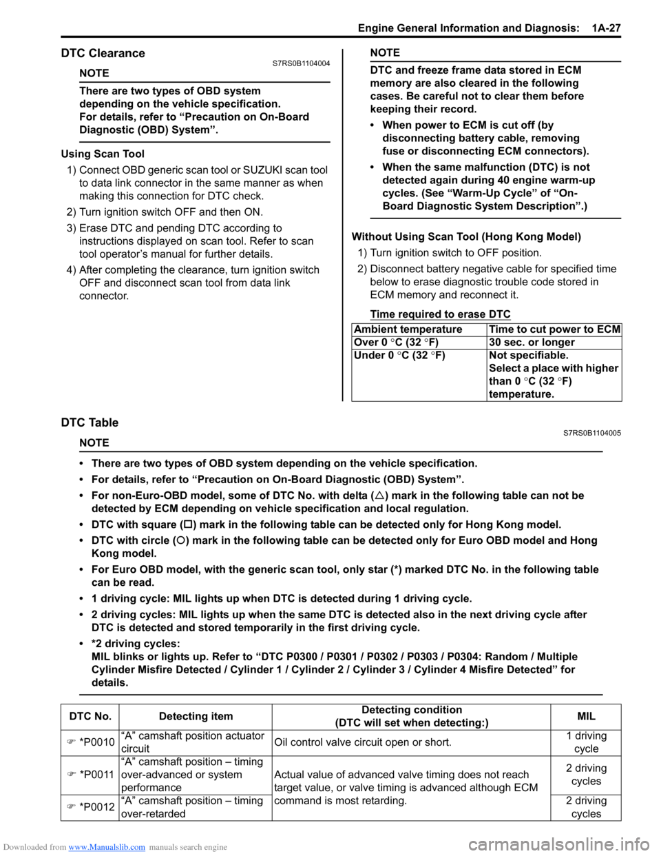
DTC ClearanceS7RS0B1104004
NOTE
There are two types of OBD system
depending on the vehicle specification.
For details, refer to “Precaution on On-Board
Diagnostic (OBD) System”.
Using Scan Tool1) Connect OBD generic scan to ol or SUZUKI scan tool
to data link connector in the same manner as when
making this connection for DTC check.
2) Turn ignition switch OFF and then ON.
3) Erase DTC and pending DTC according to instructions displayed on scan tool. Refer to scan
tool operator’s manual for further details.
4) After completing the clear ance, turn ignition switch
OFF and disconnect scan tool from data link
connector.
NOTE
DTC and freeze frame data stored in ECM
memory are also cleared in the following
cases. Be careful not to clear them before
keeping their record.
• When power to ECM is cut off (by disconnecting battery cable, removing
fuse or disconnecting ECM connectors).
• When the same malfunction (DTC) is not detected again during 40 engine warm-up
cycles. (See “Warm-Up Cycle” of “On-
Board Diagnostic System Description”.)
Without Using Scan Tool (Hong Kong Model)
1) Turn ignition switch to OFF position.
2) Disconnect battery negative cable for specified time below to erase diagnostic trouble code stored in
ECM memory and reconnect it.
Time required to erase DTC
DTC TableS7RS0B1104005
NOTE
• There are two types of OBD system depending on the vehicle specification.
• For details, refer to “Precaution on On-Board Diagnostic (OBD) System”.
• For non-Euro-OBD model, some of DTC No. with delta ( �U) mark in the following table can not be
detected by ECM depending on vehicl e specification and local regulation.
• DTC with square ( �†) mark in the following table can be detected only for Hong Kong model.
• DTC with circle ( �{) mark in the following table can be detected only for Euro OBD model and Hong
Kong model.
• For Euro OBD model, with the generic scan tool, onl y star (*) marked DTC No. in the following table
can be read.
• 1 driving cycle: MIL lights up when DTC is detected during 1 driving cycle.
• 2 driving cycles: MIL lights up when the same DTC is detected also in the next driving cycle after DTC is detected and stored temporarily in the first driving cycle.
• *2 driving cycles: MIL blinks or lights up. Refer to “DTC P0300 / P0301 / P0302 / P0303 / P0304: Random / Multiple
Cylinder Misfire Detected / Cylinder 1 / Cylinder 2 / Cylinder 3 / Cylinder 4 Misfire Detected” for
details.
Ambient temperature Time to cut power to ECM
Over 0 °C (32 ° F) 30 sec. or longer
Under 0 °C (32 °F) Not specifiable.
Select a place with higher
than 0 °C (32 °F)
temperature.
DTC No. Detecting item Detecting condition
(DTC will set when detecting:) MIL
�) *P0010 “A” camshaft position actuator
circuit Oil control valve circuit open or short. 1 driving
cycle
�) *P0011 “A” camshaft position – timing
over-advanced or system
performance Actual value of advanced va
lve timing does not reach
target value, or valve timi ng is advanced although ECM
command is most retarding. 2 driving
cycles
�) *P0012 “A” camshaft position – timing
over-retarded 2 driving
cycles
Page 88 of 1496
Downloaded from www.Manualslib.com manuals search engine 1A-38 Engine General Information and Diagnosis:
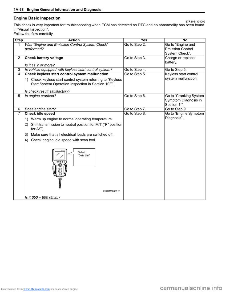
Engine Basic InspectionS7RS0B1104009
This check is very important for troubleshooting when ECM has detected no DTC and no abnormality has been found
in “Visual Inspection”.
Follow the flow carefully.Step Action Yes No 1 Was “Engine and Emission Control System Check”
performed? Go to Step 2. Go to “Engine and
Emission Control
System Check”.
2 Check battery voltage
Is it 11 V or more? Go to Step 3. Charge or replace
battery.
3 Is vehicle equipped with keyless start control system? Go to Step 4. Go to Step 5.
4 Check keyless start control system malfunction
1) Check keyless start control system referring to “Keyless
Start System Operation In spection in Section 10E”.
Is check result satisfactory? Go to Step 5. Keyless start control
system malfunction.
5 Is engine cranked? Go to Step 6. Go to “Cranking System
Symptom Diagnosis in
Section 1I”.
6 Does engine start? Go to Step 7. Go to Step 9.
7 Check idle speed
1) Warm up engine to normal operating temperature.
2) Shift transmission to neutral position for M/T (“P” position
for A/T).
3) Make sure that all electrical loads are switched off.
4) Check engine idle speed with scan tool.
Is it 650 – 800 r/min.? Go to Step 8. Go to “Engine Symptom
Diagnosis”.
I2RH01110005-01
Page 267 of 1496
Downloaded from www.Manualslib.com manuals search engine Engine General Information and Diagnosis: 1A-217
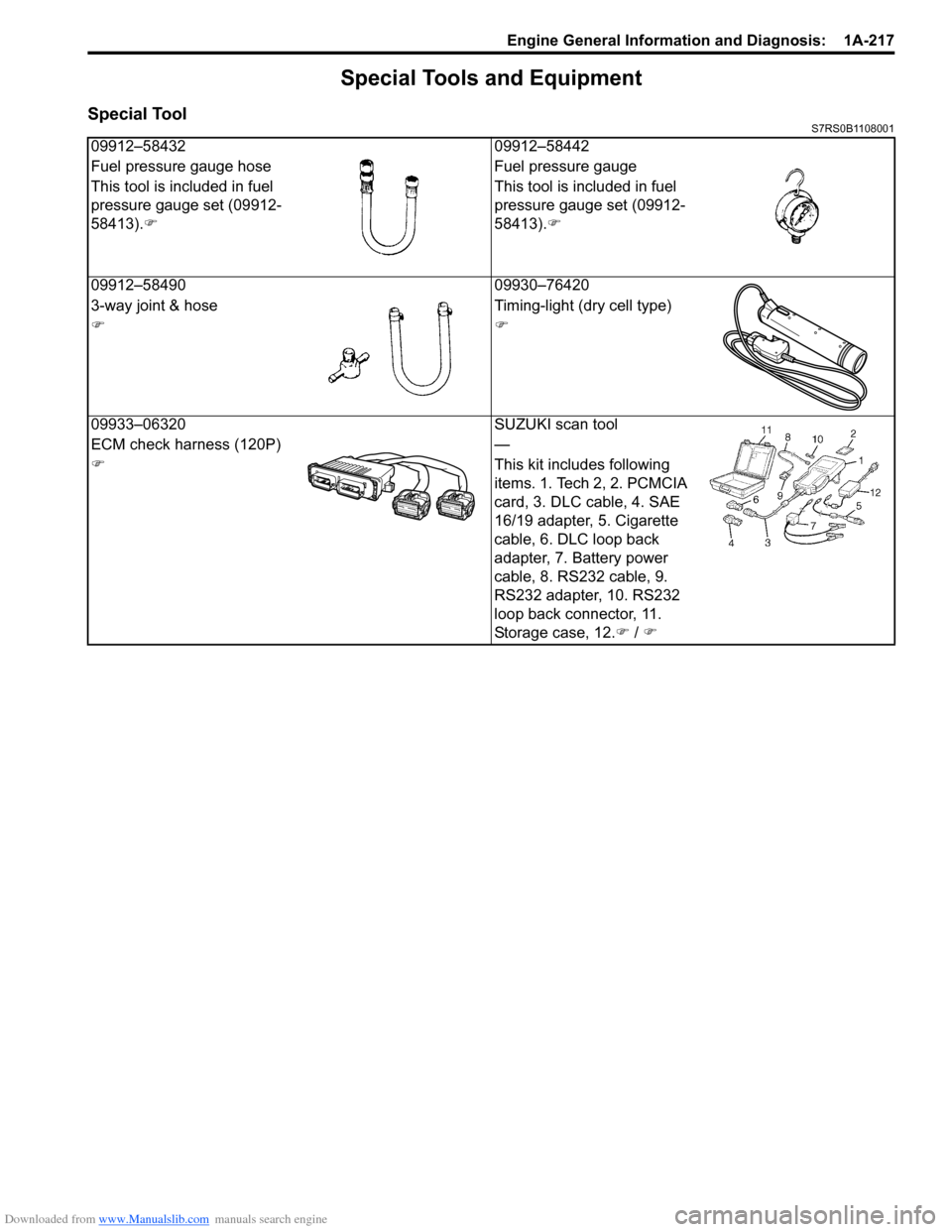
Special Tools and Equipment
Special ToolS7RS0B1108001
09912–5843209912–58442
Fuel pressure gauge hose Fuel pressure gauge
This tool is included in fuel
pressure gauge set (09912-
58413). �) This tool is included in fuel
pressure gauge set (09912-
58413).
�)
09912–58490 09930–76420
3-way joint & hose Timing-light (dry cell type)
�)�)
09933–06320 SUZUKI scan tool
ECM check harness (120P) —
�) This kit includes following
items. 1. Tech 2, 2. PCMCIA
card, 3. DLC cable, 4. SAE
16/19 adapter, 5. Cigarette
cable, 6. DLC loop back
adapter, 7. Battery power
cable, 8. RS232 cable, 9.
RS232 adapter, 10. RS232
loop back connector, 11.
Storage case, 12.�) / �)
Page 271 of 1496

Downloaded from www.Manualslib.com manuals search engine Aux. Emission Control Devices: 1B-4
EVAP Canister InspectionS7RS0B1206006
WARNING!
DO NOT SUCK nozzles on EVAP canister.
Fuel vapor inside EVAP canister is harmful.
1) Check outside of EVAP canister visually.
2) Disconnect vacuum hoses from EVAP canister.
3) Check that there is no restriction of flow through purge pipe (1) and air pipe (2) when air is blown (4)
into tank pipe (3).
If any faulty condition is found in this inspection,
replace EVAP canister.
EGR Valve Removal and InstallationS7RS0B1206007
Removal
1) Disconnect negative (–) cable at battery.
2) Remove air intake pipe.
3) Remove EGR pipe.
4) Disconnect EGR valve connector.
5) Remove EGR valve and gasket from cylinder head.
Installation
Reverse removal procedure noting the following.
• Clean mating surface of valve and cylinder head.
• Use new gaskets.
EGR Valve InspectionS7RS0B1206008
1) Check resistance between following terminals of EGR valve (1) in each pair.
If found faulty, replace EGR valve assembly.
EGR valve resistance (A – B, C – B, F – E, D – E
terminal)
20 – 24 Ω
2) Remove carbon from EGR valve gas passage.
CAUTION!
Do not use any sharp-edged tool to remove
carbon.
Be careful not to damage or bend EGR valve
(1), valve seat (3) and rod.
3) Inspect valve (2), valve seat and rod for fault, cracks, bend or other damage.
If found faulty, replace EGR valve assembly.
PCV Hose InspectionS7RS0B1206009
NOTE
Be sure to check that there is no obstruction
in PCV valve or its hoses before checking
IAC duty, for obstructed PCV valve or hose
hampers its accurate adjustment.
Check hoses for connection, leakage, clog and
deterioration.
Replace as necessary.
I4RS0A120006-01
I2RH0B120005-01
I2RH0B120006-01
Page 272 of 1496
Downloaded from www.Manualslib.com manuals search engine 1B-5 Aux. Emission Control Devices:
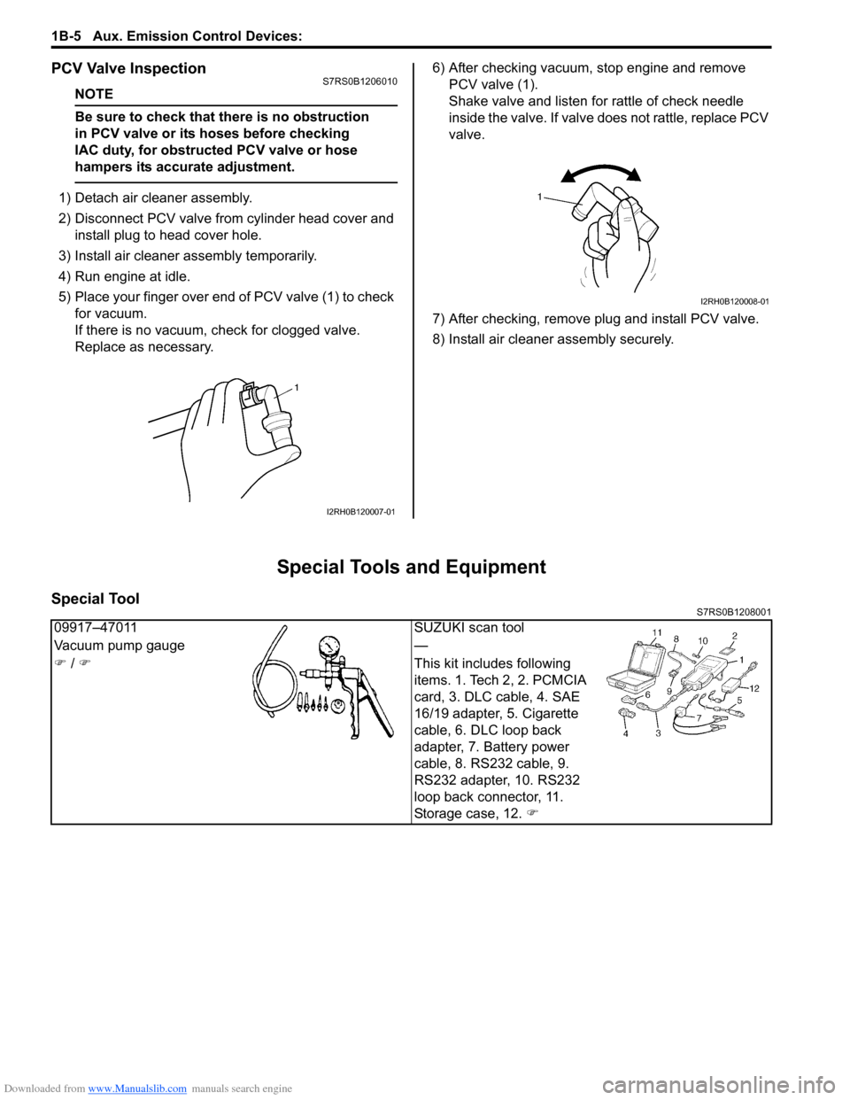
PCV Valve InspectionS7RS0B1206010
NOTE
Be sure to check that there is no obstruction
in PCV valve or its hoses before checking
IAC duty, for obstructed PCV valve or hose
hampers its accurate adjustment.
1) Detach air cleaner assembly.
2) Disconnect PCV valve from cylinder head cover and install plug to head cover hole.
3) Install air cleaner assembly temporarily.
4) Run engine at idle.
5) Place your finger over end of PCV valve (1) to check for vacuum.
If there is no vacuum, ch eck for clogged valve.
Replace as necessary. 6) After checking vacuum, stop engine and remove
PCV valve (1).
Shake valve and listen for rattle of check needle
inside the valve. If valve does not rattle, replace PCV
valve.
7) After checking, remove plug and install PCV valve.
8) Install air cleaner assembly securely.
Special Tools and Equipment
Special ToolS7RS0B1208001
I2RH0B120007-01
I2RH0B120008-01
09917–47011 SUZUKI scan tool
Vacuum pump gauge —
�) / �) This kit includes following
items. 1. Tech 2, 2. PCMCIA
card, 3. DLC cable, 4. SAE
16/19 adapter, 5. Cigarette
cable, 6. DLC loop back
adapter, 7. Battery power
cable, 8. RS232 cable, 9.
RS232 adapter, 10. RS232
loop back connector, 11.
Storage case, 12. �)
Page 273 of 1496
Downloaded from www.Manualslib.com manuals search engine Engine Electrical Devices: 1C-1
Engine
Engine Electrical Devices
Repair Instructions
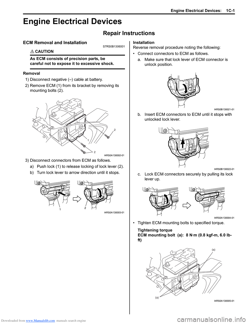
ECM Removal and InstallationS7RS0B1306001
CAUTION!
As ECM consists of precision parts, be
careful not to expose it to excessive shock.
Removal1) Disconnect negative (–) cable at battery.
2) Remove ECM (1) from its bracket by removing its
mounting bolts (2).
3) Disconnect connectors from ECM as follows. a) Push lock (1) to release locking of lock lever (2).
b) Turn lock lever to arrow direction until it stops. Installation
Reverse removal procedure noting the following:
• Connect connectors to ECM as follows.
a. Make sure that lock lever of ECM connector is unlock position.
b. Insert ECM connectors to ECM until it stops with unlocked lock lever.
c. Lock ECM connectors securely by pulling its lock lever up.
• Tighten ECM mounting bolts to specified torque. Tightening torque
ECM mounting bolt (a): 8 N·m (0.8 kgf-m, 6.0 lb-
ft)
1
2 2
I4RS0A130002-01
1
2I4RS0A130003-01
I4RS0B130021-01
I4RS0B130022-01
I4RS0A130004-01
(a) (a)I4RS0A130005-01
Page 277 of 1496
Downloaded from www.Manualslib.com manuals search engine Engine Electrical Devices: 1C-5
Electric Throttle Body System CalibrationS7RS0B1306004
NOTE
If working the service described under the
“Precautions of Electric Throttle Body
System Calibration in Section 1A” perform
following steps for electric throttle body
system calibration.
1) If electric throttle body assembly and/or APP sensor
assembly are replaced, perform following steps.
a) Disconnect negative cable at battery for 20 seconds or more for the purpose of clearing
calibration data of closed throttle position from
memory in ECM.
b) Connect negative cable to battery.
2) Keep ignition switch at ON position for 5 seconds or more without running engine.
APP Sensor Assembly On-Vehicle InspectionS7RS0B1306005
1) Check that APP sensor a ssembly has been mounted
to vehicle body properly (no pinched floor carpet,
etc.).
If mounting is not pro perly, reinstall APP sensor
assembly properly refe rring to “APP Sensor
Assembly Removal and Installation”.
2) Connect scan tool to DLC with ignition switch turned OFF.
3) Turn ON ignition switch and select “Data List” mode on scan tool.
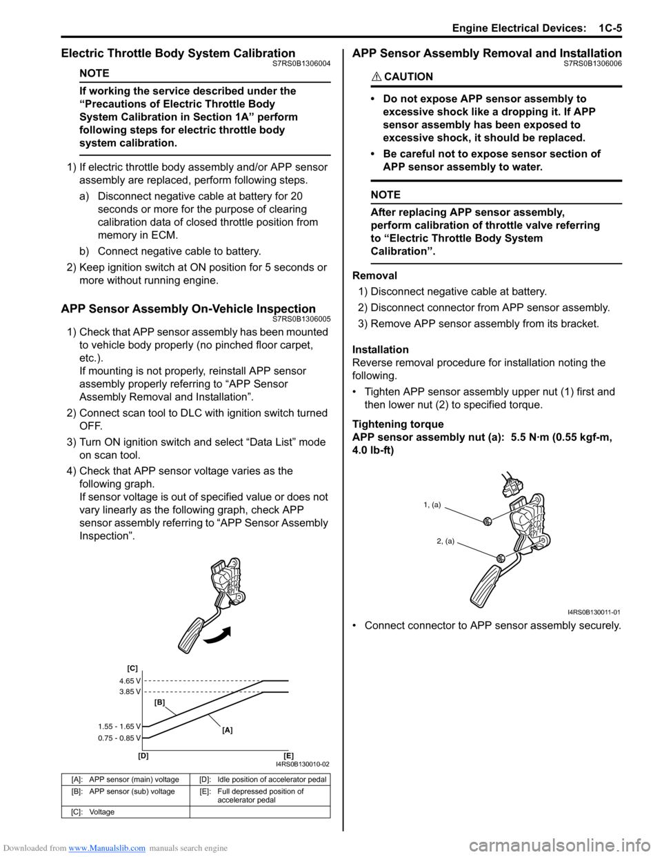
4) Check that APP sensor voltage varies as the following graph.
If sensor voltage is out of specified value or does not
vary linearly as the fo llowing graph, check APP
sensor assembly referring to “APP Sensor Assembly
Inspection”.
APP Sensor Assembly Removal and InstallationS7RS0B1306006
CAUTION!
• Do not expose APP sensor assembly to
excessive shock like a dropping it. If APP
sensor assembly has been exposed to
excessive shock, it should be replaced.
• Be careful not to expose sensor section of APP sensor assembly to water.
NOTE
After replacing APP sensor assembly,
perform calibration of th rottle valve referring
to “Electric Throttle Body System
Calibration”.
Removal
1) Disconnect negative cable at battery.
2) Disconnect connector from APP sensor assembly.
3) Remove APP sensor asse mbly from its bracket.
Installation
Reverse removal procedure for installation noting the
following.
• Tighten APP sensor assembly upper nut (1) first and then lower nut (2) to specified torque.
Tightening torque
APP sensor assembly nut (a): 5.5 N·m (0.55 kgf-m,
4.0 lb-ft)
• Connect connector to APP sensor assembly securely.
[A]: APP sensor (main) voltage [D]: Idle position of accelerator pedal
[B]: APP sensor (sub) voltage [E]: Full depressed position of
accelerator pedal
[C]: Voltage
[C]
[B]
[D] [E] [A]
4.65 V
3.85 V
1.55 - 1.65 V
0.75 - 0.85 V
I4RS0B130010-02
1, (a)
2, (a)
I4RS0B130011-01
Page 290 of 1496

Downloaded from www.Manualslib.com manuals search engine 1D-5 Engine Mechanical:
11) Connect negative cable at battery.
12) Install special tools (Compression gauge) into spark plug hole.
Special tool
(A): 09915–64512
(B): 09915–64530
(C): 09915–67010
13) Disengage clutch (1) (to lighten starting load on engine) for M/T vehicle, and depress accelerator
pedal (2) all the way to make throttle fully open.
14) Crank engine with fully charged battery, and read the highest pressure on compression gauge.
NOTE
• For measuring compression pressure, crank engine at least 250 r/min. by using
fully charged battery.
• If measured compression pressure is lower than limit value, check installation
condition of special tool. If it is properly
installed, possibility is compression
pressure leakage from where piston ring
and valve contact.
Compression pressure
Standard: 1400 kPa (14.0 kg/cm2, 199.0 psi)
Limit: 1100 kPa (11.0 kg/cm2, 156.0 psi)
Max. difference between any two cylinders: 100
kPa (1.0 kg/cm
2, 14.2 psi) 15) Carry out Steps 12) through 14) on each cylinder to
obtain 4 readings.
16) Disconnect negative cable at battery.
17) After checking, install spark plugs and ignition coil assemblies (2) with high-tension cord (3).
18) Connect ignition coil couplers (1).
19) Connect fuel injector wires (4) at the coupler.
20) Install cylinder head upper cover.
21) Install air cleaner assembly and air suction hose referring to “Air Cleaner Components”.
22) Install engine cover.
23) Connect negative cable at battery.
Engine Vacuum CheckS7RS0B1404002
The engine vacuum that develops in the intake line is a
good indicator of the condition of the engine. The
vacuum checking procedure is as follows:
1) Warm up engine to normal operating temperature.
NOTE
After warming up engine, be sure to place
transaxle gear shift lever in “Neutral”, and set
parking brake and block drive wheels.
2) Stop engine and turn off the all electric switches.
3) Remove engine cover.
4) Remove air cleaner assembly and air suction hose referring to “Air Cleaner Components”.
5) Remove PCV hose (1) from PCV valve (2).
(A)
(C)
(B)
I3RH0B140009-01
I2RH0B140005-01
I2RH0B140003-01
2
1
I6RS0B141001-01